This thread has been locked.

If you have a related question, please click the "Ask a related question" button in the top right corner. The newly created question will be automatically linked to this question.

LAUNCHXL-F28069M: Launchpad isolators

Part Number: LAUNCHXL-F28069M


Hi,

Looking at the F28069M launchpad schematic:

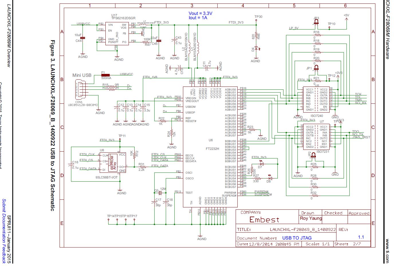
Two isolators iso7240 and iso7231 are used to isolate the target from the FT2232. That said, the schematic shows R16,18,19,20,25,28,30,32 bypassing the isolators. The BOM does not have these resistors in it. The actual PCB also has the resistors missing, even the tracks to these resistors are probably missing ?

That said JP1 and JP2 are closed as well, implying the power supply for the target is derived from the USB bus.

These resistors have 0 as designation for their values, generally 0 ohms describe a jumper, but if a jumper (since there are no pads, directly connected ?) is intended then the isolator in the schematic has no meaning ?

Or does the 0 ohms imply an open circuit ?

Any thoughts ?

Thanks,

Manu

  • Manu,

    The pads for the isolation resistors are actually just underneath the Isolators. you will notice two pads sticking out near JP1 and in between the isolators. They are 1206 pads for 0-ohm resistors to use if you decide to populate them. Doing so would permanently disable the isolation - obviously because you have to remove the ISO chips, but then also because you short the signals.

    having JP1 and JP2 shorted is also disabling the isolation.

    To actually utilize the isolation features, you actually just need to pull JP1 and JP2 shunts off the headers, and then supply the 3.3V for the MCU with an external supply. The XDS100v2 will be powered from the USB.

    Thanks,
    Mark
  • Hi Mark,

    That clears up things.

    Thanks,
    Manu