This thread has been locked.

If you have a related question, please click the "Ask a related question" button in the top right corner. The newly created question will be automatically linked to this question.

TMS320F28075: Flash Write not working

Part Number: TMS320F28075
Other Parts Discussed in Thread: C2000WARE

Hello, 

In our project, we are trying to download new firmware on Flash sectors. For that i am using flash address received from serial communication for erasing particular sector. sector is getting erased properly.After flash erase i tried to write data on flash but sometimes data write gets successful and sometimes gets fail with Fapi_Error_AsyncIncorrectDataBufferLength error.

I am using .txt file data during firmware write,

i have divided above data in address packet and data packet format and transmitting it over serial port to controller.

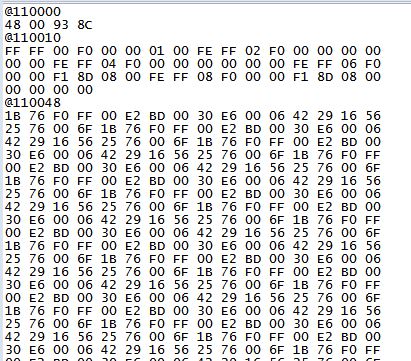
address packet @110000 = 0x88000

data packet    48 00 93 bc   - This packet getting written on flash properly

address packet @110010 = 0x88008

data packet - This packet getting written on flash properly

address packet @110048 = 0x88024

data packet - This packet generates error. After that error keeps on repeating

Can any one guide on this, why this error is getting generated.

Regards,

Sandeep

  • Sandeep,

    Please search for "How many bits can be programmed at a time using Fapi_issueProgrammingCommand()?" in Flash API wiki at: processors.wiki.ti.com/.../C2000_Flash_FAQ

    Which programming mode are you using? If you use Fapi_AutoEccGeneration mode, you can only program either 64-bits or 128-bits (on a 128-bit aligned memory) at a time.

    Please check the length of the data that you are programming at 0x88024.

    Thanks and regards,
    Vamsi
  • I tried 2 modes for writing data on flash, Fapi_AutoEccGeneration mode and Fapi_dataonly mode in both scenario i am getting an error message.

    Also as you can see in .Txt file addressing is made by Compiler to keep data on flash. In that at address 110010 i am trying to write 52 bytes . which means 128 bit * 3 (1st three lines) = 384 bits + 32 bit(4th line) = 416 bits. In this scenario how does Flash api will behave? in my scenario,416 bits are not 128 bit aligned nor 64 bits aligned still getting written on flash when i used Fapi_dataonly mode.

    From 88024 i am trying to write 64 words, which is almost 1024 bits and it looks like it is 128 bit aligned. But still generating error.

    Please let me know which mode i should use for writing data on flash. What is mean by 128 bit aligned? And what if i have to write only 32 bytes on memory then how to write.

    Regards,
    Sandeep Chavan
  • Sandeep,

    128-bit aligned (# of 16-bit words are 8) address means the memory address of your data needs to be a multiple of 8.
    For example, 0x80000, 0x80008, 0x80010, 0x80018

    64-bit aligned (# of 16-bit words are 4) address means the memory address of your data needs to be a multiple of 4.
    For example, 0x80000, 0x80004, 0x80008, 0x8000C

    Due to architectural reasons, Flash API can program a max of 128-bits at-a-time, given the address is 128-bit aligned.
    Hence, when the data is more than 128-bits, you need to call the program command for every 128-bits.

    Whether you use Fapi_DataOnly mode or Fapi_AutoEccGeneration mode, you need to make sure that the data length for a given address does not exceed the 128-bit boundary. That is what is explained with an example in the wiki that I asked you refer to.

    In the case of 0x88008, you can program 3 sets of 128-bits, then for the next set of remaining bits, you need to stream the entire 64-bits of data or 128-bits of data before you program along with ECC (since ECC gets programmed for every 64-bit aligned memory data). Please search for "Why do you use align directive (ALIGN(x)) in the linker cmd files provided in the C2000Ware examples?" in the wiki to understand better.

    Check the errata advisory "Flash: Minimum Programming Word Size" at www.ti.com/.../sprz423f.pdf . You can program either 64-bits or 128-bits only.

    Thanks and regards,
    Vamsi
  • Hello Vamsi,

    Thanks for sharing important information. I have modified ALIGN(4) to ALIGN(8) and now the text file generated is aligned to what exactly required during flash writing.

    Is it ok,  if i write FF on the highlighted place during flashing, as its empty.or should i keep it as it is.

    After writing firmware on flash i tried to boot, but controller generated illegal isr. error. Do i have to make flash off after firmware write finish. 

    Or the firmware written on the flash is having some issue.

    Regards,

    Sandeep Chavan

  • Vamsi,

    i am able to jump to application code from bootloader code, but application code is generating some issue. in Disassembly i see one error that no code at 88dcc address. But code is present on that location.

    In application code i have toggled one gpio. In debugger i saw that gpio is not getting toggled.

    but when i individually run that application on same memory, application code runs perfectly fine.

    Even i downloaded application code using ccs and then from Bootloader code to application code jump is taken , in that scenario also application code is working fine. i saw gpio toggle in debug session.

    for flash write i am using Fapi_AutoEccGeneration mode. After bootloader start i have used below sequence

    first flash sectors init

    EALLOW;
    // Flash0EccRegs.ECC_ENABLE.bit.ENABLE = 0x0;

    Fapi_StatusType oReturnCheck;
    oReturnCheck = Fapi_initializeAPI(F021_CPU0_BASE_ADDRESS, 120);
    if(oReturnCheck != Fapi_Status_Success)
    {
    Example_Error(oReturnCheck);
    }
    oReturnCheck = Fapi_setActiveFlashBank(Fapi_FlashBank0);
    if(oReturnCheck != Fapi_Status_Success)
    {
    Example_Error(oReturnCheck);
    }

    //Flash0EccRegs.ECC_ENABLE.bit.ENABLE = 0xA;

    EDIS;


    Then if address is received, on serial port i erase particular sector only once using below function


    char FlashSectorErase(uint32 Bzero_Sector_start)
    {
    char status=SET;

    Fapi_StatusType oReturnCheck;

    Fapi_FlashStatusWordType oFlashStatusWord;

    EALLOW;
    Flash0EccRegs.ECC_ENABLE.bit.ENABLE = 0x0;

    oReturnCheck = Fapi_issueAsyncCommandWithAddress(Fapi_EraseSector,(uint32 *)Bzero_Sector_start);


    // Wait until FSM is done with erase sector operation

    while (Fapi_checkFsmForReady() != Fapi_Status_FsmReady){}


    // Verify that Sector is erased. The Erase step itself does a

    oReturnCheck = Fapi_doBlankCheck((uint32 *)Bzero_Sector_start,
    Bzero_16KSector_u32length,
    &oFlashStatusWord);

    if(oReturnCheck != Fapi_Status_Success)
    {
    status = CLEAR;

    Example_Error(oReturnCheck);
    }
    Flash0EccRegs.ECC_ENABLE.bit.ENABLE = 0xA;
    EDIS;

    return status;
    }

    Then if data is received, on serial port then in bunch of 128 bit i write it on flash

    unsigned char Flashwrite( Uint16 *BufAddr, Uint16 SizeofBuf)
    {
    char status=SET;

    unsigned short i=0,increment=0;

    uint32 u32Index = 0;

    Fapi_StatusType oReturnCheck;

    volatile Fapi_FlashStatusType oFlashStatus;

    Fapi_FlashStatusWordType oFlashStatusWord;


    EALLOW;

    if(SizeofBuf % 8)
    {
    increment = SizeofBuf % 8;

    SizeofBuf += 8 - increment;

    }

    for(i=0; i< SizeofBuf; i++)
    {
    Buffer[i] = 0xFFFF;
    Buffer[i] = *BufAddr;
    BufAddr++;
    }
    Buffer[i] = 0xFFFF;


    for(i=0, u32Index =flash_address;
    (u32Index < (flash_address + SizeofBuf)); i+= 8, u32Index+= 8)
    {

    oReturnCheck = Fapi_issueProgrammingCommand((uint32 *)u32Index,Buffer+i,
    8,0,0,
    Fapi_AutoEccGeneration);

    while(Fapi_checkFsmForReady() == Fapi_Status_FsmBusy);

    if(oReturnCheck != Fapi_Status_Success)
    {
    //
    // Check Flash API documentation for possible errors
    //
    Example_Error(oReturnCheck);
    }

    //
    // Read FMSTAT register contents to know the status of FSM after
    // program command for any debug
    //
    oFlashStatus = Fapi_getFsmStatus();

    //
    // Verify the values programmed. The Program step itself does a verify
    // as it goes. This verify is a 2nd verification that can be done.
    //
    oReturnCheck = Fapi_doVerify((uint32 *)u32Index, 4, Buffer32+(i/2),
    &oFlashStatusWord);

    if(oReturnCheck != Fapi_Status_Success)
    {
    status = CLEAR;

    // Check Flash API documentation for possible errors
    //
    Example_Error(oReturnCheck);
    }
    }
    // Flash0EccRegs.ECC_ENABLE.bit.ENABLE = 0xA;

    EDIS;

    if(oReturnCheck != Fapi_Status_Success)
    {
    status = CLEAR;
    }

    return status;
    }


    after finishing the firmware download, using jump instruction to jump to application code.

    Please let me know if i missed something

    Regards,
    Sandeep Chavan

  • Sandeep,

    Regarding your question on filling the holes with 1s: If you don't have plans to use those holes at run time (like program those locations using API embedded in to your application), you can program 1s along with ECC.

    Regarding illegal ISR: In your application, do you have any code allocated to .TI.ramfunc that you forgot to copy from Flash to RAM before executing? Please check.

    Regarding the code that you shared: I may not be able to go through the code. But, I think your concern is to make sure that all the content is programmed correctly - Yes? If so, you can compare the memory dump of your application for the CCS load case vs your boot program case.

    I would suggest to fix above things first before further debug.

    Also, please open a different post with further questions since this post is about programming Flash using API.

    Thanks and regards,
    Vamsi
  • Sandeep,

    Were you able to resolve the illegal ISR issue?
    Can I close this thread?

    Thanks and regards,
    Vamsi
  • Sandeep,

    Since I did not hear from you in the last 2+ weeks, I am assuming you resolved your issue using our debug tips. I am closing this thread. You can open a new thread as needed.

    Thanks and regards,
    Vamsi