This thread has been locked.

If you have a related question, please click the "Ask a related question" button in the top right corner. The newly created question will be automatically linked to this question.

CCS/TMS320F28035: Simulink c28x_LedBlink_ert

Part Number: TMS320F28035


Tool/software: Code Composer Studio

Hello,

I was playing around with the F28035 simulink example file: "c28x_LedBlink_ert"
After the program was loaded, I clicked on the "Open project in Code Composer Studio" in the simulink "Diagnostic Viewer". In the CCS watch window, I was going through the register values and had a few questions (4 questions):

1) I have read the TI documentation "SPRUGL8C" (http://www.ti.com/lit/ug/sprugl8c/sprugl8c.pdf) and on page 97 - Table 72, I see that GPIOs 0 to 11 have their pull ups disabled, is this because the GPIOs 0 to 11 are PWMs and since PWMs are outputs the pull ups are disabled? (there are other peripherals on these GPIO pins, so why disable only the first 12 GPIOs)

2) On the same page of the document, why arent GPIOs 40 & 41 pull up disabled by default as well? After all, they are ePWM7A & ePWM7B respectively (based on "SPRS584L" page 20 - http://www.ti.com/general/docs/lit/getliterature.tsp?genericPartNumber=tms320f28032&fileType=pdf).

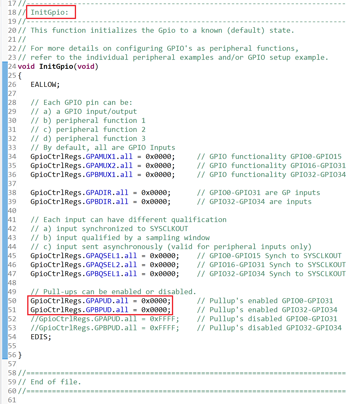
3) However in the CCS watch window for "c28x_LedBlink_ert", things are consistent, i.e. "GPAPUD" by default has a value 0x00000FFF (pull up disabled for GPIOs 0 to 11), similarly "GPBPUD" has a default value of 0x00000300 (pull up disabled for GPIO 40 & 41). However I can't seem to find the file that initializes the registers with the mentioned values, in fact the "DSP280x_Gpio.c" initializes the pull ups using the following two lines:

GpioCtrlRegs.GPAPUD.all = 0x0000;
GpioCtrlRegs.GPBPUD.all = 0x0000;

So there has to be another file overwriting these registers, could I be directed to that file/function? For instance the "GPxDIR" are overwritten in the "c28x_LedBlink_ert_test.c" file.  

4) The "c28x_LedBlink_ert" toggles the GPIO pins 31 & 34, so that means that those GPIOs should be set as outputs, looking at the watch window I observe that "GPADIR" has a value of 0x80000000 (i.e. GPIO 31 = output) and "GPBDIR" has a value of 0x00000004 (i.e. GPIO 34 = output), so things are consistent. However shouldn't the pull ups be disbaled since these are outputs? Shouldn't "GPAPUD" be 0x80000FFF and "GPBPUD" be 0x00000304?

Thanks in advance

  • PWM pins are usually the olny pins with their pulls-ups disabled... this is not always true though.

    I quickly read your post it looks like you think GPIOs 40 and 41 are incorrectly documented, is that correct?

    Thanks,
    Cody 

  • Thanks for addressing this post Cody. 

    I had multiple questions in my post. My first one was "why do PWMs have their pull ups disabled", and what you are saying is that there is no specific reason for doing that.

    My next question is: The F2803x processor family has PWM7A and 7B on GPIO 40 & 41, so just to keep things consistent, shouldn't they have their pull ups disabled as well? Probably the documentation provided by TI could be revised (based on your previous response of there being no specific reason of doing that, I guess it doesn't really matter).


  • Alex,

    there is always a good reason if a pull up is disabled on a pin. In the case of PWM pins: PWMs often control a high power gate driver, if the PWM incidentally went high for a few moments during power on then electrical damage could occur. Additionally we recommend that if a low state is desired on start up that the customer use an external pull-down resistor.

    If you wish to know the default configuration of the build in pullups simply look at the default value in GPAPUD and GPBPUD that you have shown above. For example GPIO0 (R/W-1) is listed as a bit with read and write capabilities with a default state of 1 on reset. 

    Regards,
    Cody 

  • Again, thank you for your reply Cody.

    Cody Watkins said:
    PWMs often control a high power gate driver, if the PWM incidentally went high for a few moments during power on then electrical damage could occur.

    The mux registers (for example "GPAMUX1") by default are set to "00", however the PWMs are Peripheral "01", so would the scenario you have suggested ever actually occur on power on? Even if it did, with the pull up enabled the pin would have a voltage level of Vdd and the PWM gate driver would also be trying to drive a voltage of Vdd, right? so how would there be electrical damage? 

    Following up on that, which file actually initializes the "default register values after reset". The documentation clearly states that registers are initialized to certain values after reset. Even if I create a blank project in CCS, with just one blank main.c file and no other linked header files, the registers are initialized to their correct values (verified by the watch window). Is it the .gel file?

    Thanks in advance

  • The GPIO and the PWM use the same IO buffer so the pull-up will be there in both cases. If the device didn't drive a value it could float to a unknown state. 

    The PWMs often control high power electronics(much higher than VDD) that need to be switched a very specific rate, turning the gate on for too long may ( and usually does) destroy components.

    The default register values are handled in hardware not software...It also may be worth saying that they're not configurable.

    Regards,
    Cody 

  • Thanks for your reply Cody, that cleared things up. 

    Cody Watkins said:

    The default register values are handled in hardware not software...It also may be worth saying that they're not configurable.

    Could you point me to the documentation describing your above statement.

    Thanks 

  • Alex,
    Sorry, I just notice you had a follow-up question. If you look at the register description tables they will have something like R/W - n, where 'n' indicates the value at start up.

    I don't know anywhere in the documentation where we say that we do not have software configurable default values for GPIOs, but I think this is because it's difficult to document features you don't have. Satirically put: The F28035 device doesn't make coffee, and the documentation will likely never indicate this fact.

    Note:If we had a feature on an old device and it was removed, that would be very clearly stated in the documentation.

    Hope it helps,
    Cody