


Part Number: TMS320F28035
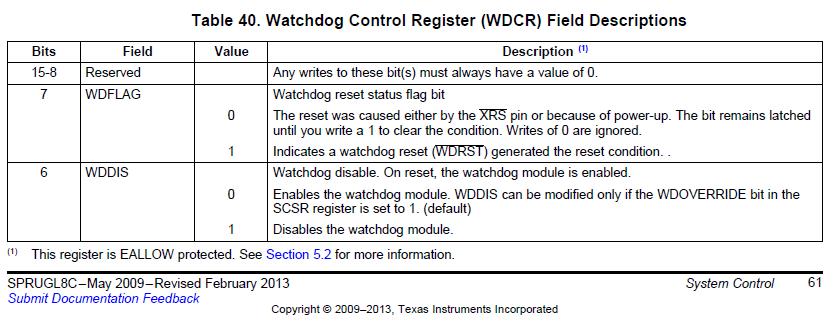
In our application, we need to be able to identify the reset-source so I’m using the WDFLAG bit in the WDCR register.
The first function in main() is to read-out the value of WDCR register.
In our testing of Model_1, we always get WDFLAG=1 even if the DSP reset was due to power-up. The same function implemented in Model_2, at power-up we get WDFLAG=0 which the correct and expected value.
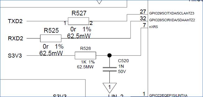
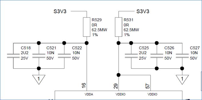
I checked and compared the schematics of Model_1 and Model_2, both are the same and also the same component values assembled. Below is a schematic screenshot of the nXRS and VDD pins to show the circuit and values assembled.
Questions:
1. Model_1 and Model_2 have the same circuits, but why do I get different WDFLAG values during power-up?
2. In Model_1, if I increase C520=10uF, then I get the expected WDFLAG=0. Model_2 is ok with C520=1nF but Model_1 needs 10uF. Any ideas what is causing the difference?
a. Note: C520=1uF still does not work
3. Increasing C520=10uF obviously means that nXRS pin is low much longer, so DSP is in reset much longer.
a. There is a note in the Ref Guide to have the external reset be longer in duration than the watchdog pulse. If I’m not mistaken, WDRST pulse is OSCCLK x 512. We are using the Internal Clock, so 10MHz, which gives 51.2us pulse duration.
b. R528=1K, C520=1nF Tn=1us… less than 51.2us
c. R528=1K, C520=1uF Tn=1000us… greater than 51.2us, but still does not work. Any idea why this still does not work?
d. R528=1K, C520=10uF Tn=10000us… greater than 51.2us, this works. What is the recommended value?
Regards, Bernd


