This thread has been locked.

If you have a related question, please click the "Ask a related question" button in the top right corner. The newly created question will be automatically linked to this question.

CCS/TMS320F28377S: DSP-28377S-ADC-Sampling error

Part Number: TMS320F28377S


Tool/software: Code Composer Studio

Dear all;

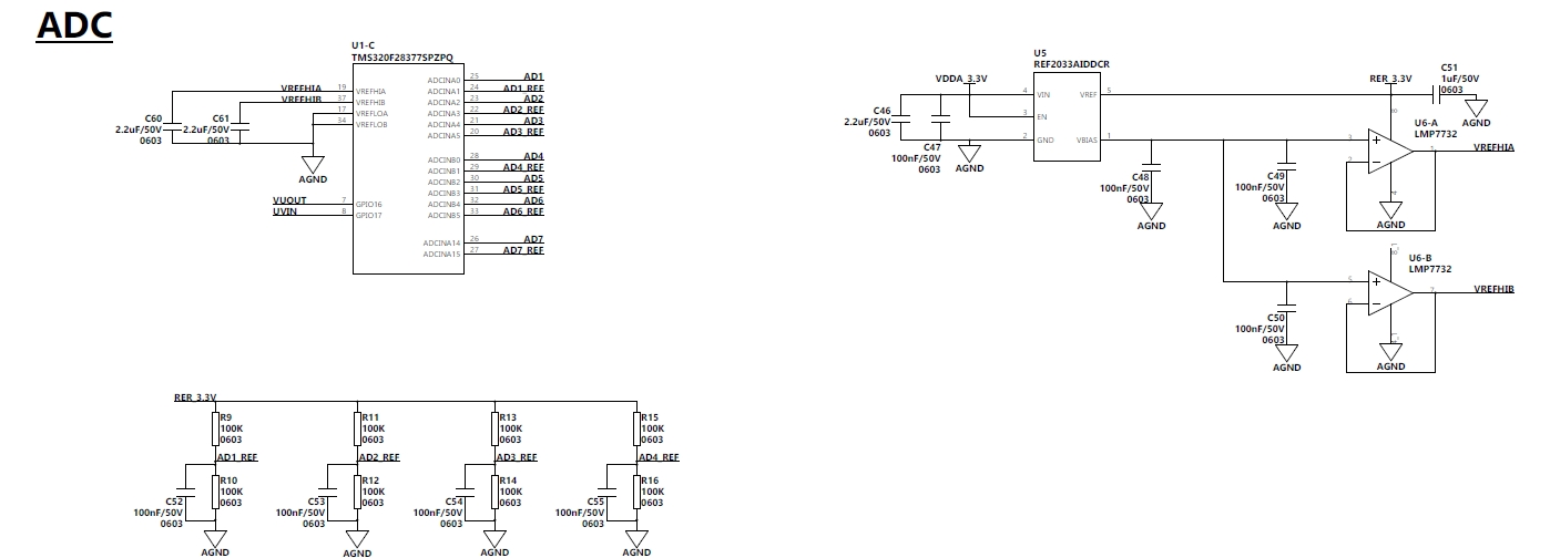
I am using the DSP-28377S , Now I fond the ADC value is not right.  I used  50 DSP  chips, the same software, There are 20  right , 30 are error. As follows:

DSP-ADC:

 1、ADC_RESOLUTION_16BIT,      ADC_SIGNALMODE_DIFFERENTIAL

2、red curve is ADC-A0-A1 channel,  white is ADC-A2-A3 channel, green is  ADC-A4-A5 channel, 

3、the red curve value (A0-A1 channel)  is  always correct. 

erro:

correct:

Code:

void ADC_capture()
{


AdcaRegs.ADCSOCFRC1.all = 0x007F; //SOC0 and SOC1

while(AdcaRegs.ADCINTFLG.bit.ADCINT1 == 0);

AdcaRegs.ADCINTFLGCLR.bit.ADCINT1 = 1;


AdcaResult0 = AdcaResultRegs.ADCRESULT0; ///1--3

AdcaResult2 = AdcaResultRegs.ADCRESULT2;

AdcaResult4 = AdcaResultRegs.ADCRESULT4;

}


//Write ADC configurations and power up the ADC for both ADC A and ADC B
void ConfigureADC(void)
{

EALLOW;

//write configurations
AdcaRegs.ADCCTL2.bit.PRESCALE = 6;   //set ADCCLK divider to /4

AdcSetMode(ADC_ADCA, ADC_RESOLUTION_16BIT, ADC_SIGNALMODE_DIFFERENTIAL);

AdcaRegs.ADCCTL1.bit.INTPULSEPOS = 1; // AdcaRegs.ADCCTL1.bit.INTPULSEPOS = 1;

AdcaRegs.ADCCTL1.bit.ADCPWDNZ = 1;

EDIS;


}


void SetupADCSoftware(void)
{

Uint16 acqps;

//determine minimum acquisition window (in SYSCLKS) based on resolution
if( 0 && ADC_RESOLUTION_12BIT == AdcaRegs.ADCCTL2.bit.RESOLUTION){
acqps = 14; //75ns
}
else { //resolution is 16-bit
acqps = 63; //63--320nS 
}

//Select the channels to convert and end of conversion flag
//------------------ADCA-------------------------------------------------------
EALLOW;

AdcaRegs.ADCSOC0CTL.bit.CHSEL = 0; //SOC0 will convert pin A0
AdcaRegs.ADCSOC0CTL.bit.ACQPS = acqps; //sample win


AdcaRegs.ADCSOC1CTL.bit.CHSEL = 1; //SOC1 will convert pin A1
AdcaRegs.ADCSOC1CTL.bit.ACQPS = acqps; //sample window is acqps + 1 SYSCLK cycles
// AdcbRegs.ADCSOC1CTL.bit.TRIGSEL = 1;


AdcaRegs.ADCSOC2CTL.bit.CHSEL = 2; //SOC1 will convert pin A1
AdcaRegs.ADCSOC2CTL.bit.ACQPS = acqps; //sample window is acqps + 1 SYSCLK cycles
//AdcbRegs.ADCSOC2CTL.bit.TRIGSEL = 1;


AdcaRegs.ADCSOC3CTL.bit.CHSEL = 3; //SOC1 will convert pin A1
AdcaRegs.ADCSOC3CTL.bit.ACQPS = acqps; //sample window is acqps + 1 SYSCLK cycles


AdcaRegs.ADCSOC4CTL.bit.CHSEL = 4; //SOC1 will convert pin A1
AdcaRegs.ADCSOC4CTL.bit.ACQPS = acqps; //sample window is acqps + 1 SYSCLK cycles
//AdcbRegs.ADCSOC4CTL.bit.TRIGSEL = 1;


AdcaRegs.ADCSOC5CTL.bit.CHSEL = 5; //SOC1 will convert pin A1
AdcaRegs.ADCSOC5CTL.bit.ACQPS = acqps; //sample window is acqps + 1 SYSCLK cycles


AdcaRegs.ADCINTSEL1N2.bit.INT1SEL = 5; //end of SOC1 will set INT1 flag
AdcaRegs.ADCINTSEL1N2.bit.INT1E = 1; //enable INT1 flag
AdcaRegs.ADCINTFLGCLR.bit.ADCINT1= 1; //make sure INT1 flag is cleared

}

I can not found why it is, Please. Thanks.

  • Hi Jeff,

    In your SetupADCSoftware() function, you only need to define the EVEN channel for the differential pair, for example if you use pair A0/A1 for SOC0 you will only need the statements:

    AdcaRegs.ADCSOC0CTL.bit.CHSEL = 0; //SOC0 will convert pin A0/A1 if 16-bit differential mode is used
    AdcaRegs.ADCSOC0CTL.bit.ACQPS = acqps; //sample win

    and for SOC1, your statements should be:

    AdcaRegs.ADCSOC1CTL.bit.CHSEL = 2; //SOC1 will convert pin A2/A3 if 16-bit differential mode is used
    AdcaRegs.ADCSOC1CTL.bit.ACQPS = acqps; //sample win

    and for SOC2, your statements should be:

    AdcaRegs.ADCSOC2CTL.bit.CHSEL = 4; //SOC2 will convert pin A4/A5 if 16-bit differential mode is used
    AdcaRegs.ADCSOC2CTL.bit.ACQPS = acqps; //sample win

    You will need to be checking only for SOC0, SOC1 and SOC3 with corresponding conversion results from registers AdcaResultRegs.ADCRESULT0, AdcaResultRegs.ADCRESULT1 and AdcaResultRegs.ADCRESULT2.


    This should fix your issue.

    Regards,
    Joseph
  • Hi Regards,
    Thanks for your help, according to your suggestion,I changed the software,but it doesn't work,maybe the hardware is wrong ,Can you give me some other approaches.


    Regards,
    Jeff
  • Hi Jeff,

    Ok, we can start looking at your schematics for the differential pairs you are using,

    Regards,

    Joseph

  • Hi, Joseph,

    SCH as followed:

  • Hi Jeff,

    I have a couple of questions regarding your schematic diagrams:

    1.) What is providing RFR_3.3V and what is the exact voltage you measure there?
    2.) What is the input circuit in AD1-AD6? I'm asking about any RC network.
    3.) What is the amplitude of the input signals to AD1 to AD6?

    Thanks and regards,
    Joseph
  • Hi Jeff,

    I'm concerned about the signal going to the odd channel in the differential pair. It seems like the odd channels are steadily biased to VREF/2. If you are converting in differential mode, the common mode voltage spec of (VREF/2) -/+ 50mv is violated if this is the input circuit. A proper way to create a differential input for the TMS320F28377S from a single-ended source like what is shown in your schematic is to use a single-ended to fully differential op-amp. For the differential signal, the positive input for the even channel is of the opposite polarity as the signal in the negative input channel.

    Best regards,
    Joseph