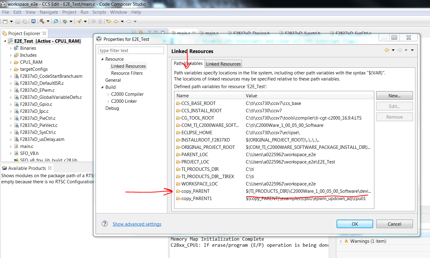
This thread has been locked.
If you have a related question, please click the "Ask a related question" button in the top right corner. The newly created question will be automatically linked to this question.
Hello everyone,
I see a strange behaviour on an ePWM when high-resolution period control is enabled. I don't need to actually use TBPRDHR or CMPAHR to see this behaviour, just setting the HRPCTL[HRPE] bit is enough to make it appear.
I have a very simple program which configures EPWM8 for up-down high-resolution period/duty control with TBPRD = 180, then switches between CMPA = 36 and CMPA = 144 in a loop.
Here is the code:
_eallow(); ClkCfgRegs.PERCLKDIVSEL.bit.EPWMCLKDIV = 1; CpuSysRegs.PCLKCR0.bit.TBCLKSYNC = 0; CpuSysRegs.PCLKCR2.bit.EPWM1 = 1; CpuSysRegs.PCLKCR2.bit.EPWM8 = 1; CpuSysRegs.PCLKCR0.bit.HRPWM = 1; EPwm8Regs.TBCTL.bit.CLKDIV = TB_DIV1; EPwm8Regs.TBCTL.bit.HSPCLKDIV = TB_DIV1; EPwm8Regs.TBCTL.bit.CTRMODE = TB_COUNT_UPDOWN; EPwm8Regs.TBCTL.bit.PRDLD = TB_SHADOW; EPwm8Regs.TBCTL.bit.PHSEN = TB_ENABLE; EPwm8Regs.CMPCTL.bit.LOADAMODE = CC_CTR_ZERO_PRD; EPwm8Regs.CMPCTL.bit.SHDWAMODE = CC_SHADOW; EPwm8Regs.AQCTLA.bit.CAD = AQ_SET; EPwm8Regs.AQCTLA.bit.CAU = AQ_CLEAR; EPwm8Regs.TBPRD = 180; EPwm8Regs.CMPA.all = 18; EPwm8Regs.HRCNFG.bit.EDGMODE = HR_BEP; EPwm8Regs.HRCNFG.bit.CTLMODE = HR_CMP; EPwm8Regs.HRCNFG.bit.HRLOAD = HR_CTR_ZERO_PRD; EPwm8Regs.HRCNFG.bit.AUTOCONV = 1; EPwm8Regs.HRPCTL.bit.HRPE = 1; EPwm8Regs.HRPCTL.bit.TBPHSHRLOADE = 1; CpuSysRegs.PCLKCR0.bit.TBCLKSYNC = 1; EPwm8Regs.TBCTL.bit.SWFSYNC = 1; __edis(); while (SFO() != SFO_COMPLETE); __eallow(); GpioCtrlRegs.GPCDIR.bit.GPIO86 = 1; GpioCtrlRegs.GPCDIR.bit.GPIO87 = 1; GpioCtrlRegs.GPAMUX1.bit.GPIO14 = 1; __edis(); for (;;) { /* Pulse on GPIO86 when setting CMPA to small value */ GpioDataRegs.GPCSET.bit.GPIO86 = 1; __asm(" RPT #50 || NOP"); EPwm8Regs.CMPA.bit.CMPA = 18; GpioDataRegs.GPCCLEAR.bit.GPIO86 = 1; DELAY_US(10); while (EPwm8Regs.TBSTS.bit.CTRDIR != 1); /* Pulse on GPIO87 when setting CMPA to big value */ GpioDataRegs.GPCSET.bit.GPIO87 = 1; __asm(" RPT #50 || NOP"); EPwm8Regs.CMPA.bit.CMPA = 162; GpioDataRegs.GPCCLEAR.bit.GPIO87 = 1; DELAY_US(10); while (EPwm8Regs.TBSTS.bit.CTRDIR != 1); }
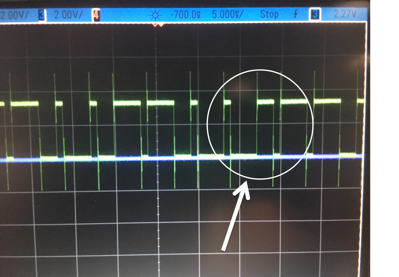
Here is a picture of the result:
Here is the same picture zoomed in and annotated by myself:
However if I leave HRPE disabled the problem disappears and everything goes as expected.
Can someone from TI reproduce the problem using the code I provided? Is there an explanation for this behaviour?
Cheers,
Pierre
Pierre
Hello Nima,
Please find attached the smallest CCS project I could put together to show the problem.
I run it on a TMS320F28379D controlCard but I guess it would work the same on a LaunchPad since I clock the CPU using the internal oscillator.
Please let me know as soon as possible if you manage to reproduce the problem, this is a critical issue for my project.
Kind regards,
Pierre
Hello Nima,
Thanks for your answer.
I'm looking forward to solving this issue. This delay creates the equivalent of a digital low-pass filter in my control system (with transfer function (1 + z^-1)/2 ) and it will decrease the performance of the system.
Regards,
Pierre
Pierre,
The response I got from the team was different from your findings. With HRPE = 0, There still seems to be the same issue.
Cody Watkins do you have any idea what could be causing this?
e2e_epwm_overclocked_fixed.zip
Okay I just checked and you are running EPWM at 180MHz... The maximum frequency for the EPWM clock is 100MHz on this device.
I have an identical example with the same settings as you with EPWM6 and it works fine when the EPWM clock is 100MHz. I stripped out all of the HRPWM code and the issue was always there, Then I created my own project with the clocks running off of crystal and system set to 200MHz and EPWM set to 100MHz, same exact code works.
Nima Eskandari
Hello Nima,
I have several issues with your answer and the project you sent. Please see below:
1. Non-portable projects are inconvenient
The project I sent you is self-contained project so that you only need to compile it and run it. My code uses the internal oscillator so that it works the same regardless of the crystal frequency (which is 20MHz on the controlCard and 10MHz on the LaunchPad).
The project you sent me, on the other hand, has dependencies on external libraries and it doesn't compile because it has the path to C2000Ware from your machine hardcoded in it. This is impractical so from now on can we agree to stick to portable projects with no dependencies to external files?
2. My issue is still present in the project you sent
After manually resolving the path to every C2000Ware file I ran your project. If I uncomment the configuration of the HRPWM the issue appear exactly as I described it. Therefore I suspect that the issue you recreated is not exactly the same one I had.
4. Additional information
Since we have different results running the same code I think we need to pay attention to non-code things. Here is the information I can think about:
Thank you for your help. I hope we'll be able to find what's wrong with my code or my setup.
Cheers,
Pierre
Pierre,
Again thank you for your patience.
1. Porting My C2000WARE project
The project I sent to you should be easily ported to your CCS. Everything is linked, and all you would need to do to make sure it can run on your setup is change a the paths in the Project Properties. If you are resolving each file manually, that is NOT the way to go.
I can now see EXACTLY what you were saying on my Control Card.
Pierre,
I believe I finally have the solution and explanation for your problem. I’m going to try it out on my control card and post it for you.
Nima Eskandari
Nima,
I'm glad to hear it.
In case it helps, I have noticed that the PWM behaves as expected if the pulses are centered on the CTR=PRD event instead of the CTR=ZRO event (i.e rising edge on CAU, falling edge on CAD and write to CMPA shadow when the counter starts counting down). I don't know how high-resolution period control works internally but maybe it processes the two events differently in HRP mode?
Cheers,
Pierre
Well seems like you beat me to it. But here is the full explanation.
When using HR mode with UP-DOWN timer mode, you must set the load mode for your shadow registers to be PRD AND ZERO. But in HR mode this does not mean your shadow register gets updated on both PRD and ZERO. It actually only gets updated on ZERO. This is what I was not aware of and seems to be the answer to your solution. When using HR mode in UP/DOWN you want to always center the Pulse around PRD because that is what the HR mode internally will try to do.
The reason you set shadow load mode to PRD and ZERO is internally there is another shadow of the register (double shadow) which will get updated. The user has no control over this. The user's shadow register will only get updated on ZERO and the pulses should always center around PRD.
As always thank you Pierre for you question and your patience. Digging into this actually helped me understand the HR mode more deeply as well.
Nima Eskandari
Yes yes, sorry. Loads on ZERO, centers around PRD.
I do write the TRM section for ePWM and I am going to add this description to the TRM.
Also, knowing the limmitation that in HR Mode it only loads shadow registers on ZERO, the UP-DOWN mode wont work the way you want it to.
So I think you can implement this using UP-Mode and doing all the HR calculations in your software.
what we can do is close this thread, open a new thread and ask this question. Then we can both work to see if we can do all the calculations in the PWM-ISR and change the Action qualifiers and CMPAHR to get it to center around both PRD and ZERO.