This thread has been locked.

If you have a related question, please click the "Ask a related question" button in the top right corner. The newly created question will be automatically linked to this question.

TMS320F28377D: Is it possible that PWM-A and PWM-B have a phase offset?

Part Number: TMS320F28377D

In the new product design, my company wants to use the PWM abilities of the DSP in order to control the motion of a 3-phase rotary motor, which has 3 phases (R, S and T). According to this design, PWM1A should control axis 1R, PWM1B - axis 1S, PWM2A - axis 1T. (Channels C and D will be used for other purposes). Due to the nature of the motor, the phases R, S and T should have 120° phase shift. At the beginning, PWM is set to 50%, therefore CMPA and CMPB are set to EPWM_TIMER_TBPRD/2.

However, as far as I understand, PWM1 has only one counter and four comparators, CMPA, CMPB, CMPC and CMPD. CMPA and CMPB define the thresholds for controlling PWM channels A and B. Thus, if CMPA and CMPB are set to the same value, (namely, EPWM_TIMER_TBPRD/2), they will create events simultaneously, since there is only one counter, — which contradicts to the 120° phase shift requirement. Thus, I proposed to use PWM1A for axis 1S, PWM2A for axis 1R, and PWM3A for axis 1T; implementing phase shift between PWM1, PWM2 and PWM3 will be easy. But this requires layout changes of the PCB, and the management is not happy with my proposal.

Please advice: is there a possibility to implement phase shift between PWM1A and PWM1B? If yes, how?

Thanks,
Alexey.

  • Alexey,

    I think I understand your issue. Your suggestion to use PWM1A, PWM2A and PWM3A would have been the easiest way to go since it would have allowed you to use PHSEN, and create a phase shift. Then depending on how your motor controller circuit is, you could have used PWM1A and PWN1B in complimentary mode to generate complimentary PWM signals (possibly with some deadband) to control the high side and lowside switch that controls a Phase of the motor.

    But now lets concentrate on how we can change the software to create phase shifted PWM signals on PWM1A, 1B and 2A. since you already have a PCB.

    First thing I want to let you know is that CMPA and CMPB values can both be used to change the output on PWM1A. Same for PWM1B. What I'm trying to say is that  the A and B in CMPA or CMPB  are not related to the A and the B in PWM1A and PWM1B.

    Example: 


    Ok so now lets think about it. We can control EPWM1A with CTR=0, CTR=CMPA, CTR=CMPB, and CTR=PRD. You can choose count-up mode for PWM or count-up-down depending on how complex you want your signals to be. Same thing can be done with EPWM1B but we do different actions at CTR = 0, CMPA, CMPB and PRD. If you use Count Up/Down, you can even take advantage of two more events, CMPA (during count up/during count down) and CMPB (during count up and count down).

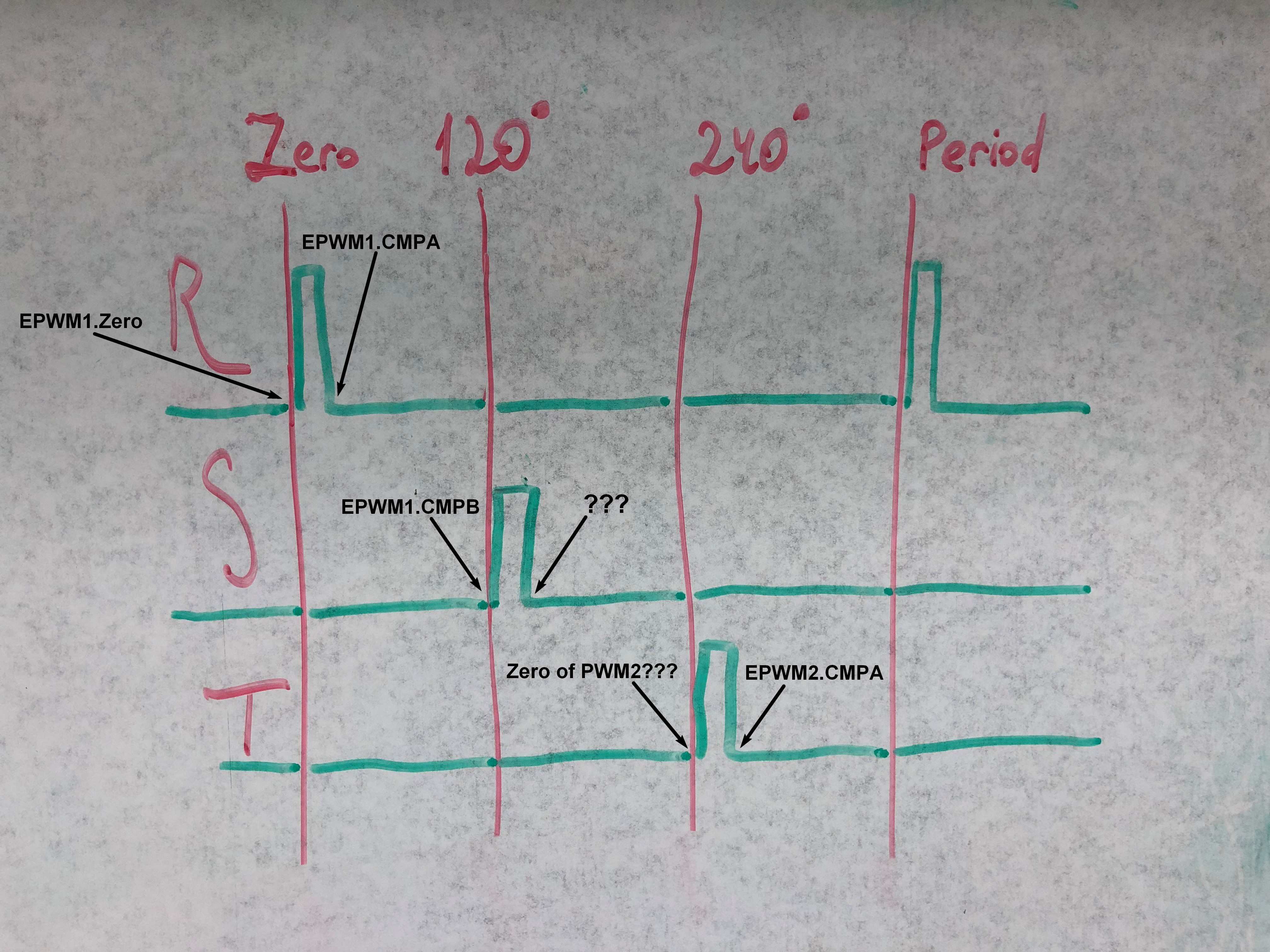
    So here is a little example I did on my whiteboard for you. EPWM1A, EPWM1B and EPWM2A phase shifted!

    Here is what I did, you set CMPA and CMPB to the corresponding values in EPWM1Regs. Set EPWM1 in count up mode.

    For EPWM1A,

    1. on CTR = 0, Set the output

    2. on CTR = CMPA, clear the output.

    3. on CTR = CMPB no action (or clear... no difference really)

    For EPWM1B,

    1. on CTR = 0, clear the output

    2. on CTR = CMPA, set the output.

    3. on CTR = CMPB clear the output

    Configure EPWM2 to sync to EPWM1. Make EPWM2.CMPA = EPWM1.CMPB. You can have to change EPWM2.CMPA every time you can EPWM1,CMPB...

    1. on CTR = 0, clear the output

    2. on CTR = CMPA, Set the output

    I hope you now know how to make these signals, you can generate way more complex signal, using count up-down mode.

    Nima Eskandari

  • Nima,

    Thanks for your reply, it explains a lot. However, I still don't see a way to implement a lower percentage of PWM. Consider the following picture:

    The EPWM*.Period is constant for all PWM channels and can't be changed, this is a prerequisite, therefore I can't use it for limiting the pulse of phase S (point labeled "???"). CMPC and CMPD are used for other purposes and can't be used for the point labeled "???" anyway. I simply don't see the resources I need to implement this setup.

    Additionally, there is a strong push to move the pulses to the center of the corresponding bands, with peaks at around 60° for phase R, 180° for phase R and 300° for phase T, in order to reduce noise while measuring currents on the phases. That means, I won't be able to use EPWM1.Zero for beginning of pulse on phase R, and won't be able to use EPWM2.Zero for beginning of pulse of phase T. 

    The difference between beginnings of pulses of phase R, S and T absolutely must be 120° at all times, therefore I can't use up-down counter and set CMPA for beginning of pulse R and end of pulse S, and CMPB for end of pulse R and beginning of pulse S. In other words, the following setup is illegal:

    That leaves me with insufficient comparators to fulfill the requirements, am I right?

    Thanks,
    Alexey.

  • Alexey I have another idea. First, lets make things more complicated by moving the pulses to the center. I would like to give an answer to the original situation.

    Here is what I think you should do.

    Divide your original PWM PERIOD by 3. We will now have three specific conditions. AGAIN this solution is doable but you need to write the software for it.

    You need to keep track which one of the three conditions you are in (between the 3 stages).

    In the first stage, DUTY cycle of S and T are zero, and R is given the needed duty.

    In the second stage DUTY cycle of R and T are zero and S is given the needed duty.

    In the third stage DUTY cycle of S and R are zero and T is given the needed duty.

    AND REPEAT. Keeping track of which third you are in. Since your PRD is divided by 3, you can use shadow mode and get this working perfectly without HW change needed.

  • Let's **not** make things more complicated!
  • Try to implement the solution above and let me know how it goes!