Because of the holidays, TI E2E™ design support forum responses will be delayed from Dec. 25 through Jan. 2. Thank you for your patience.

This thread has been locked.

If you have a related question, please click the "Ask a related question" button in the top right corner. The newly created question will be automatically linked to this question.

CCS/TMDSCNCD28035: Error Connecting to the Target

Part Number: TMDSCNCD28035
Other Parts Discussed in Thread: CONTROLSUITE, TMS320F28035

Tool/software: Code Composer Studio

CCS gives an error when I try to debug. Error says,"Error Connecting to the target".

I am trying to build and run examples pre-built for F28035 control card. and I am very new to this world and do forgive me for errors.

To do so. I followed the steps given in the guide by Ti (Major Points but not all). (Control Card is in default state as shipped) SW1- off SW2-on, on Works with GUI when right COM port is selected and motor speed was controlled through that GUI. No idea how to check COM Ports in CCS. 

Errors:

Compiling Errors:

Any suggestions? I am totally new to this was used to plug and play of Arduino platforms. I have used an example from C:\ti\controlSUITE\development_kits\HVMotorCtrl+PfcKit_v2.0\HVPM_Sensorless. with CCSv8 setup.

  • Praneel,

    none of your images came through, can you re-upload and try again. here is a resource to help you do that: e2e.ti.com/.../149.4-3-inserting-an-image-on-e2e

    Which guide are you following?

    -Mark
  • I have done some edit to this post which shows images but I am still stick with connection and don't know what's wrong with the setup of CCS.
    I have used an example from C:\ti\controlSUITE\development_kits\HVMotorCtrl+PfcKit_v2.0\HVPM_Sensorless
    I have used an CCSv8

  • Praneel,

    First,  your program is not compiling. It looks like you have probably included two linker command files. in your project settings you have defined a linker file that will be included. Additionally, I assume that if you look at the files included in the project, there will be an additional linker file. CCS will try to use both which will cause that error. Choose which you prefer to have in your project, and then remove the other.

    For the second error during connection, please work through the guide: http://www.ti.com/lit/spracf0

    -Mark

  • Based on my understanding,  I understand that in project there is an linker file (.ccxml) and there is one (.ccxml) maintained automatically. 

    So, to solve it I did this, Clicked on Manage the project-target configuration automatically, as can be seen below in attached figure. and I deleted the one I defined and finally, I have only one target configuration. (Now I believe I only have one target configuration)

    As can be seen here now I have only one target configuration. 

    Still I guess I have an error:

    So any suggestions? Also the link you gave for connection error does not seem to work. 

    By the way I am using this device. 

    I have CCSv8 and I don't know what should the PID values need to be. Maybe I need to reinstall CCS and select something during instillation. I have no idea. And I guess it is getting complex. 

  • Praneel,

    I am referring to the Linker command file, not the target configuration file. something like this. "28035_RAM_lnk.cmd" .

    Please check:
    Properties -> General -> Linker command file - currently is listed as "28035_RAM_lnk.cmd"
    Properties-> Include Options -> Specify a preinclude file -> is there another linker file listed?
    In the Project Explorer view , verify if there is "28035_RAM_HVPM_Sensorless.CMD" listed (I am assuming so)

    Ensure that there is only one included. it probably needs to be the 28035_RAM_HVPM_Sensorless.CMD file since it is a custom linker file for the project.

    Please look at the C2000 Workshop and ensure that you understand what a linker file is and how they are included and used. (processors.wiki.ti.com/.../C2000_Archived_Workshops


    -Mark
  • I have looped in the JTAG debug expert, he should be able to help with the connection issue.

    The SPRACF0 guide provides a lot of information and flows to go through and also requests See Step 18 in the JTAG Debug Flow. please reply with the requested information in a concise list. It will help us understand where in the flow the issue is coming.

    Thanks,
    Mark
  • Part Number: TMDSCNCD28035

    Tool/software: Code Composer Studio

    Hi  there,

    I have error connecting target to CCS. 

    Hardware Setup: with Piccolo F2803x with SW1: OFF SW2: 1,2:ON/ON SW3:OFF/OFF

     2. CCS Version Version - CCS6.1.2

    3. Debug Probe Used - Texas Instrument XDS100v1 USB Debug Probe 

    4. Type of target: TI made 

    5. Confirmation of which steps in this guide were taken

    Note: I have not done any re-flash, It is in default state send as send from Ti. Plus, GUI motor control works when changing the COM Port but it gives me error while loading GUI.

    But GUI works when select right port. Any suggestions?

    Oh by the way, I have not flashed the Control Card yet.   

  • I am still not able to solve the connection issue. To do so, I have tried following steps.

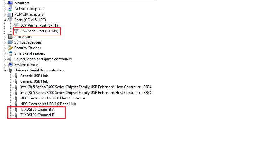
    1. Verify that USB is correctly configured to PC.

    2. So I try to use this serial number while building 

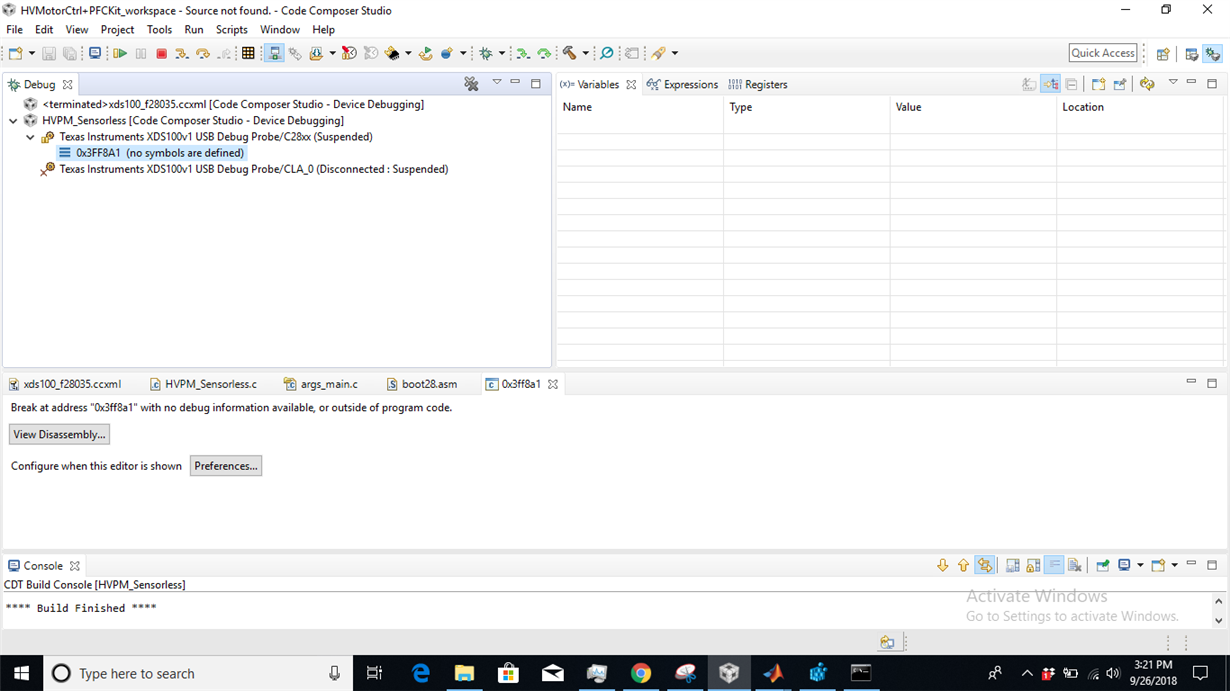
    3. Even after using this I get this suspended info:

    I was supposed to see variables load in the watch window but I could not see any.

    But I also believe, when I see the disconnect option that means the board is connected. But I was supposed to get different values on watch window but could not find any.

    Can someone also please verify this for me:

    The given documentation gives, (I am talking about TMDSHVMTRPFCKIT which has Piccolo (TMS320F28035) control card )

    So Am I supposed to have this Jumper J9 installed all the time (I don't have ISO-DIMM)? I am talking about TMDSHVMTRPFCKIT which has Piccolo (TMS320F28035) control card attached to it.Please do note I went through the document file HVMotorCtrl+PFCKit_HowToRunGuide_CCSv5.pdf. After reading that file I had doubts so I want to conform those doubts. So, will jumper be installed J9 all the time even if AC power or DC power is supplied to the board?

  • You are correct, that since you are not using the ISODIMM that you need to keep J9 shorted/jumpered. This is TRSTn signal that is needed by the emulator to keep the emulation connection active with the F2803x device.

    Best,
    Matthew
  • Hi there,

    I went through it once again and I found there is only one linker included. 28035_RAM_HVPM_Sensorless.CMD file since it is a custom linker file for the project. But I might try running more simplify project. Anyway thanks. I will spent more time to know the hardware better.