This thread has been locked.

If you have a related question, please click the "Ask a related question" button in the top right corner. The newly created question will be automatically linked to this question.

CCS/TMS320F28069M: SPIA RXBUF gets 65535

Part Number: TMS320F28069M
Other Parts Discussed in Thread: TMS320F28069, C2000WARE

Tool/software: Code Composer Studio

I have written below code for getting data from encoder using SPIA

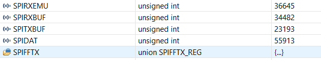
I started initially by sending dummy data(0x73) from F28069 to RLS encoder but RXBUF and RXEMU reads 65535 all the time.

SPI Mode is 0.

I doubt my SPIBRR calculation , still I calculated as 90M/8*15200 = 0x61

Below is my code. Please suggest where I am going wrong to get correct data from encoders

In oscilloscope , I can see MOSI,SCK and CS signal as required but MISO is always high

#include "DSP28x_Project.h" // Device Headerfile and Examples Include File

// Prototype statements for functions found within this file.
Uint16 spi_xmit(Uint16 a);
void spi_fifo_init(void);
void spi_init(void);
void error(void);

void delay_loop( );
int n=0;
int m=0;
//int i=0;


Uint16 sdata; // send data
Uint16 sdata1;
Uint16 rdata=0; // received data
Uint16 rdata1=0;
Uint16 rdata2=0;
Uint16 rdata3=0;
int flag=1;
//void putsUart0(Uint16 str)
//{
//Uint16 i;
//for (i = 0; i < strlen(str); i++)
// putcUart0(str[i]);
//}

void main(void)
{

// Step 1. Initialize System Control:
// PLL, WatchDog, enable Peripheral Clocks
// This example function is found in the F2806x_SysCtrl.c file.
InitSysCtrl();

// Step 2. Initalize GPIO:
// This example function is found in the F2806x_Gpio.c file and
// illustrates how to set the GPIO to it's default state.
// InitGpio(); // Skipped for this example 
// Setup only the GP I/O only for SPI-A functionality
// This function is found in F2806x_Spi.c
InitSpiaGpio();

// Step 3. Clear all interrupts and initialize PIE vector table:
// Disable CPU interrupts 
DINT;

// Initialize PIE control registers to their default state.
// The default state is all PIE interrupts disabled and flags
// are cleared. 
// This function is found in the F2806x_PieCtrl.c file.
InitPieCtrl();

// Disable CPU interrupts and clear all CPU interrupt flags:
IER = 0x0000;
IFR = 0x0000;

// Initialize the PIE vector table with pointers to the shell Interrupt 
// Service Routines (ISR). 
// This will populate the entire table, even if the interrupt
// is not used in this example. This is useful for debug purposes.
// The shell ISR routines are found in F2806x_DefaultIsr.c.
// This function is found in F2806x_PieVect.c.
InitPieVectTable();

// Step 4. Initialize all the Device Peripherals:
// This function is found in F2806x_InitPeripherals.c
// InitPeripherals(); // Not required for this example
spi_fifo_init(); // Initialize the Spi FIFO
spi_init(); // init SPI

// Step 5. User specific code:
// Interrupts are not used in this example. 
sdata = 0x73;
sdata1=0x00;

for(;;)
{
// GpioCtrlRegs.GPAPUD.bit.GPIO19 = 1;
// Transmit data


spi_xmit(sdata);
delay_loop();
// Wait until data is received
while(SpiaRegs.SPIFFRX.bit.RXFFST !=1) { }
//rdata1 =spi_xmit(sdata);

// Wait until data is received
// while(SpiaRegs.SPIFFRX.bit.RXFFST !=1) { }
//
// Check against sent data
rdata = SpiaRegs.SPIRXBUF ;
// delay_loop();


}
}

// Step 7. Insert all local Interrupt Service Routines (ISRs) and functions here:

void error(void)
{
__asm(" ESTOP0"); // Test failed!! Stop!
for (;;);
}
void delay_loop( )
{
int i;
for (i = 0; i < 1000; i++){}

}

void spi_init()
{ 
SpiaRegs.SPICCR.all =0x000F; // Reset on, rising edge, 16-bit char bits //llop back mode is enabled
SpiaRegs.SPICTL.all =0x0006; // Enable master mode, normal phase,
// enable talk, and SPI int disabled.
SpiaRegs.SPIBRR = 0x61;
SpiaRegs.SPICCR.all =0x008F; // Relinquish SPI from Reset
SpiaRegs.SPIPRI.bit.FREE = 1; // Set so breakpoints don't disturb xmission
}

Uint16 spi_xmit(Uint16 a)
{
SpiaRegs.SPITXBUF=a;
return a;
}

void spi_fifo_init() 
{
// Initialize SPI FIFO registers
//SpiaRegs.SPIFFTX.all=0xE040;
SpiaRegs.SPIFFTX.all=0xE040;
SpiaRegs.SPIFFRX.all=0x2044;
// SpiaRegs.SPIFFRX.all=0x6060F;
SpiaRegs.SPIFFCT.all=0x00;
}

//===========================================================================
// No more.
//===========================================================================

  • Ayushi,

    Please use the Code SyntaxHighlighter when inserting code or attach the file instead. It helps to make the post more readable and is collapsible! The following thread shows how to do this. https://e2e.ti.com/support/archive/helpcentral/f/301/p/622715/2295495  I have edited your post to show how useful this feature is.

    That being said, 

    1. Please verify the GPIO configuration is correct.
    2. Verify that this pin can be toggled in GPIO mode.
    3. disconnect the encoder, connect the SIMO pin to SOMI for an external loopback. Is the transmitted code received correctly?

    Thanks,
    Mark

  • This is how I initialize GPIO

    #if DSP28_SPIA
    void InitSpiaGpio()
    {
    
       EALLOW;
        GpioCtrlRegs.GPAPUD.bit.GPIO16 = 1;   // Enable pull-up on GPIO16 (SPISIMOA)
        GpioCtrlRegs.GPAPUD.bit.GPIO17 = 1;   // Enable pull-up on GPIO17 (SPISOMIA)
        GpioCtrlRegs.GPAPUD.bit.GPIO18 = 1;   // Enable pull-up on GPIO18 (SPICLKA)
        GpioCtrlRegs.GPAPUD.bit.GPIO19 = 1;   // Enable pull-up on GPIO19 (SPISTEA)
    
    
        GpioCtrlRegs.GPAQSEL2.bit.GPIO16 = 3; // Asynch input GPIO16 (SPISIMOA)
        GpioCtrlRegs.GPAQSEL2.bit.GPIO17 = 3; // Asynch input GPIO17 (SPISOMIA)
        GpioCtrlRegs.GPAQSEL2.bit.GPIO18 = 3; // Asynch input GPIO18 (SPICLKA)
        GpioCtrlRegs.GPAQSEL2.bit.GPIO19 = 3; // Asynch input GPIO19 (SPISTEA)
    
        GpioCtrlRegs.GPAMUX2.bit.GPIO16 = 1; // Configure GPIO16 as SPISIMOA
        GpioCtrlRegs.GPAMUX2.bit.GPIO17 = 1; // Configure GPIO17 as SPISOMIA
        GpioCtrlRegs.GPAMUX2.bit.GPIO18 = 1; // Configure GPIO18 as SPICLKA
        GpioCtrlRegs.GPAMUX2.bit.GPIO19 = 1; // Configure GPIO19 as SPISTEA
        EDIS;
    }
    #endif // endif DSP28_SPIA
    

    IN loop back mode I get following data

    GPIO modes are toggling

  • Ayushi,

    1. What were the results of #3 from my last request? If you do a wire-loopback of the SPI, does it correctly receive the data? If you disconnect only the SPISOMI line (data output from the encoder) and observe the status on a scope. does it toggle as you would expect?
    2. I do not know the protocol for an RLS encoder, but have you verified that you are transmitting the correct commands?
    3. Are both the clock polarity and clock phase correct and match what the encode requires?
    4. Is the SPI clock rate valid for the encoder?
    5. is the Chip select signal toggling appropriately per the encoder requirements?

    Thanks,
    Mark

  • Data look likes the attached image for spitx and spirx buffer but the weird thing is when I connect MISO and MOSI lines together oscilloscope shows signals for MOSI pin but the MISO pin stays high forever.

    I checked the protocols for RLS , its sending desired commands
    Yes its MODE 0 , so clock phase and Clock Polarity are set to 0
    Regarding SPI clock rate , can you please explain in detail how to calculate that,
    My encoder max frequency is 4MHZ , TMS320f28069 has 90MHZ frequency, I want to give clksys /4 and baudrate equal to 9600 to encoder .
    Yes, Chip select is toggling as per requirement
  • Encoder frequency rate is 4Mhz and TMS320f28069 gives 90 Mhz , I need to divide system clock by approx 22 to get 4mhz.
    Can you guide me on how to do that?
  • Ayushi,

    The SPI baud rate calculation is clearly described in the SPI chapter of http://www.ti.com/lit/spruh18  in the "Baud Rate and Clocking Schemes" section.

    Even though you say MODE 0, this is not a standardized naming convention. Refer to the "SPI Clocking Schemes" Section to ensure that the transmit and receive edges are set up as the encoder requires.

    What hardware are you using? are you sure that there is nothing else connected to the SIMO pin? 

    Are you able to successfully run the SPI loopback example provided in C2000WARE? If you disable the internal loopback functionality and connect SPISIMO and SPISOMI together, do you get the same results?

    -Mark

  • Ayushi,

    It has been a few days since your last post. I am going to mark this thread closed. If you are still facing this issue, please respond to my previous questions, and we can continue to debug this.

    Thanks,
    Mark