This thread has been locked.
If you have a related question, please click the "Ask a related question" button in the top right corner. The newly created question will be automatically linked to this question.
Hi,
I have the following Bourns encoder
connected to the launchpad GPIO24, GPIO25 as per the following schematic:
I am using the following code to read the encoder position:
// Encoder is connected to QEP_B // ENC_A is connected to EQEP2A (GPIO24) // ENC_B is connected to EQEP2B (GPIO25) void init_eqep2_gpio(void) { EALLOW; // Enable internal pull-up for the selected pins // Pull-ups can be enabled or disabled by the user. // This will enable the pullups for the specified pins. GpioCtrlRegs.GPAPUD.bit.GPIO24 = 1; // Disable pull-up on GPIO24 (EQEP2A) GpioCtrlRegs.GPAPUD.bit.GPIO25 = 1; // Disable pull-up on GPIO25 (EQEP2B) GpioCtrlRegs.GPAPUD.bit.GPIO26 = 1; // Disable pull-up on GPIO26 (EQEP2I) GpioCtrlRegs.GPAPUD.bit.GPIO27 = 1; // Disable pull-up on GPIO27 (EQEP2S) // Inputs are synchronized to SYSCLKOUT by default. GpioCtrlRegs.GPAQSEL2.bit.GPIO24 = 0; // Sync to SYSCLKOUT GPIO24 (EQEP2A) GpioCtrlRegs.GPAQSEL2.bit.GPIO25 = 0; // Sync to SYSCLKOUT GPIO25 (EQEP2B) GpioCtrlRegs.GPAQSEL2.bit.GPIO26 = 0; // Sync to SYSCLKOUT GPIO26 (EQEP2I) GpioCtrlRegs.GPAQSEL2.bit.GPIO27 = 0; // Sync to SYSCLKOUT GPIO27 (EQEP2S) // Configure eQEP-1 pins using GPIO regs // This specifies which of the possible GPIO pins will be eQEP1 functional // pins. GpioCtrlRegs.GPAMUX2.bit.GPIO24 = 2; // Configure GPIO24 as EQEP2A GpioCtrlRegs.GPAMUX2.bit.GPIO25 = 2; // Configure GPIO25 as EQEP2B GpioCtrlRegs.GPAMUX2.bit.GPIO26 = 2; // Configure GPIO26 as EQEP2I GpioCtrlRegs.GPAMUX2.bit.GPIO27 = 2; // Configure GPIO27 as EQEP2S EDIS; } void init_qcap(void) { EQep2Regs.QUPRD = 800000; // Unit Timer for 100Hz at 80 MHz SYSCLKOUT EQep2Regs.QDECCTL.bit.QSRC = 0; // QEP quadrature count mode // EQep2Regs.QDECCTL.bit.SOEN = 1; // Enable position compare EQep2Regs.QEPCTL.bit.FREE_SOFT = 2; EQep2Regs.QEPCTL.bit.PCRM = 1; // PCRM = 1 mode - QPOSCNT reset on max position EQep2Regs.QPOSMAX = 0x32; // max value is 50 EQep2Regs.QEPCTL.bit.QPEN = 1; // QEP enable EQep2Regs.QCAPCTL.bit.UPPS = 5; // 1/32 for unit position EQep2Regs.QCAPCTL.bit.CCPS = 6; // 1/64 for CAP clock EQep2Regs.QCAPCTL.bit.CEN = 1; // QEP Capture Enable } void main(void) { uint16_t i = 0, r = 0, pos; InitSysCtrl(); init_mcbspa_gpio(); /* setup gpio for mcbspa/spi */ init_eqep2_gpio(); /* setup gpio for encoder */ DINT; InitPieCtrl(); IER = 0x0000; IFR = 0x0000; InitPieVectTable(); EALLOW; PieVectTable.DINTCH1 = &isr_dma_ch1; /* Tx ISR DMA CH1 INT7.1 */ EDIS; init_qcap(); dma_init(); /* dma initialization alone */ setup_lcd_pins(); /* setup LCD RESET, D/C pins */ ssd1306_reset(); /* Reset LCD */ PieCtrlRegs.PIECTRL.bit.ENPIE = 1; /* Enable PIE block */ PieCtrlRegs.PIEIER7.bit.INTx1 = 1; /* Enable PIE Group 7 INT1(DMA CH1) */ IER = 0x40; /* Enable CPU INT Group 7 */ EINT; /* Enable Global Interrupts */ while (1) { pos = (int) EQep2Regs.QPOSCNT; rad_graph(pos); DELAY_US(2000); } }
I do see values being changed in the QPOSCNT register as can be seen in the debugger view.
I have a LCD also connected to the McBSP peripheral, which displays the QPOSCNT value.
The value I can see changing on the display as well, but the values seem to jump around with no relation eg: rotating the encoder the jump seem to be with much large values for a single turn of the encoder. Wondering how to address the issue ?
Is the issue addressable with the UPPS and the CCPS bits in the QCAPCTL register ?
ie :
EQep2Regs.QCAPCTL.bit.UPPS = 5; // 1/32 for unit position
EQep2Regs.QCAPCTL.bit.CCPS = 6; // 1/64 for CAP clock
GPIO24 and GPIO25 are configured for the encoder alone and nothing else.
I have a scope connected to GPIO25, I see a waveform on the pin, even when the encoder is not being turned, as seen in the picture:
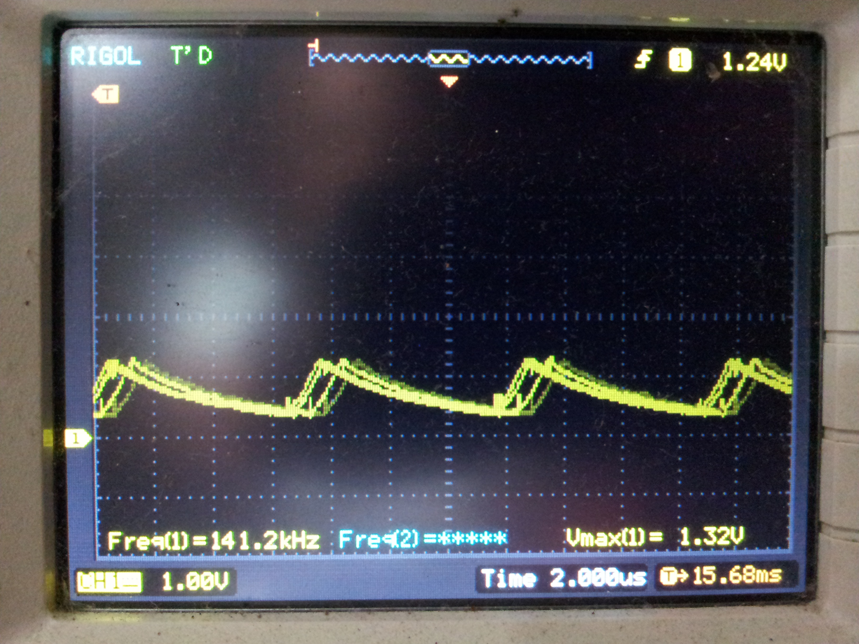
confused on the situation and hence my questions:
1. I am confused why the QPOSCNT value jumps around ? Is it probably due to the timer being configured incorrectly ?
2. Why is there a signal being generated by the controlled on the encoder input line ?
Any thoughts ?
Thanks,
Manu
Hi Manu,
Could you try using GPIO55 for EQEP2B instead of GPIO25 and see if the issue is still there? Sounds like this issue is likely related to the following advisory in the F2806x errata (www.ti.com/.../sprz342):
Advisory eQEP: Incorrect Operation of EQEP2B Function on GPIO25 Pin (This advisory is applicable for the 100-pin packages only.)
Best,
Kevin
Hi Kevin,
Removed U2 (TXB0106) from the Launchpad; used GPIO55 instead which did solve the encoder from going nuts.
While that issue is fixed, I face yet another issue:
I set POSMAX to a certain value and would like the counter not to overflow the max value, much like you have a floor and ceiling values set. ie, I would like to have the behaviour of the encoder set that the counter cannot subtract more than the floor value, nor it be able to add more than the ceiling values set. I was wondering how to achieve the behaviour. Currently, the code is simple set with max value, but whatever I try to do, the counter does overflow the ceiling values.
/** * Encoder is connected to QEP_B * ENC_A is connected to EQEP2A (GPIO24) * ENC_B is connected to EQEP2B (GPIO55) * eQEP: Incorrect Operation of EQEP2B Function on GPIO25 Pin */ void init_eqep2_gpio(void) { EALLOW; GpioCtrlRegs.GPAPUD.bit.GPIO24 = 1; /* Disable pullup GPIO24(EQEP2A) */ GpioCtrlRegs.GPBPUD.bit.GPIO55 = 1; /* Disable pullup GPIO55(EQEP2B) */ GpioCtrlRegs.GPAQSEL2.bit.GPIO24 = 0; /* Sync to SYSCLKOUT GPIO24(EQEP2A) */ GpioCtrlRegs.GPBQSEL2.bit.GPIO55 = 0; /* Sync to SYSCLKOUT GPIO55(EQEP2B) */ GpioCtrlRegs.GPAMUX2.bit.GPIO24 = 2; /* Configure GPIO24 as EQEP2A */ GpioCtrlRegs.GPBMUX2.bit.GPIO55 = 2; /* Configure GPIO55 as EQEP2B */ EDIS; } void init_qcap(void) { EQep2Regs.QUPRD = 800000; /* 100Hz at 80MHz SYSCLKOUT */ EQep2Regs.QDECCTL.bit.QSRC = 0; /* QEP quadrature count mode */ EQep2Regs.QDECCTL.bit.XCR = 1; /* 1x resolution, count rising edge */ EQep2Regs.QPOSINIT = 0; /* Initial position is 0 */ EQep2Regs.QPOSMAX = 400; /* max value is 400 */ EQep2Regs.QEPCTL.bit.FREE_SOFT = 2; EQep2Regs.QEPCTL.bit.PCRM = 3; /* QPOSCNT reset mode */ EQep2Regs.QCAPCTL.bit.UPPS = 0; /* unit position */ EQep2Regs.QCAPCTL.bit.CCPS = 0; /* CAP clock */ EQep2Regs.QEPCTL.bit.QPEN = 1; /* QEP enable */ EQep2Regs.QCAPCTL.bit.CEN = 1; /* QEP Capture Enable */ }
Any thoughts how to address the issue ?
Thanks,
Manu
I was wondering, something like this:
/* INT5.2 is eQEP2 */ __interrupt void isr_eqep2(void) { EALLOW; PieCtrlRegs.PIEACK.all = PIEACK_GROUP5; /* Interrupt ACK */ if (EQep2Regs.QFLG.bit.PCO == 1) { //Position counter overflow interrupt flag // EQep2Regs.QCLR.bit.PCO = 1; } if (EQep2Regs.QFLG.bit.PCU == 1) { //Position counter underflow interrupt flag EQep2Regs.QCLR.bit.PCU = 1; } if (EQep2Regs.QFLG.bit.PCM == 1) { // compare match event interrupt flag EQep2Regs.QCLR.bit.PCM = 1; } EDIS; return; } void init_qcap(void) { EQep2Regs.QUPRD = 800000; /* 100Hz at 80MHz SYSCLKOUT */ EQep2Regs.QDECCTL.bit.QSRC = 0; /* QEP quadrature count mode */ EQep2Regs.QDECCTL.bit.XCR = 1; /* 1x resolution, count rising edge */ EQep2Regs.QPOSINIT = 0; /* Initial position is 0 */ EQep2Regs.QPOSMAX = 400; /* max value is 400 */ EQep2Regs.QPOSCMP = 400; /* compare to this value */ EQep2Regs.QEPCTL.bit.FREE_SOFT = 2; EQep2Regs.QEPCTL.bit.PCRM = 3; /* QPOSCNT reset mode */ EQep2Regs.QCAPCTL.bit.UPPS = 0; /* unit position */ EQep2Regs.QCAPCTL.bit.CCPS = 0; /* CAP clock */ EQep2Regs.QEPCTL.bit.QPEN = 1; /* QEP enable */ EQep2Regs.QCAPCTL.bit.CEN = 1; /* QEP Capture Enable */ EQep2Regs.QEINT.bit.PCO = 1; /* counter overflow int enable */ EQep2Regs.QEINT.bit.PCU = 1; /* counter underflow int enable */ }
Struggling to get a foot hold in there.
Any thoughts ?
Thanks,
Manu
Update:
Logical reasoning made me believe the following would work:
/* INT5.2 is eQEP2 */ __interrupt void isr_eqep2(void) { EALLOW; PieCtrlRegs.PIEACK.all = PIEACK_GROUP5; /* Interrupt ACK */ if (EQep2Regs.QFLG.bit.PCO == 1) { EQep2Regs.QCLR.bit.PCO = 1; /* position counter has overflown */ EQep2Regs.QPOSCNT = EQep2Regs.QPOSMAX; /* reset position counter to max */ } if (EQep2Regs.QFLG.bit.PCU == 1) { EQep2Regs.QCLR.bit.PCU = 1; /* position counter has underflown */ EQep2Regs.QPOSCNT = EQep2Regs.QPOSINIT; /* reset position conter to min */ } if (EQep2Regs.QFLG.bit.PCM == 1) { EQep2Regs.QCLR.bit.PCM = 1; /* position counter match condition */ } EDIS; return; }
On an overflow, I do get 0x49 and on an underflow I do get 0x29, which implies that the interrupt does happen and I am able to trap the overflow and underflow events. But that said, in the debug mode, register view the expectation was that QFLG would be reset after the interrupt as I do clear the interrupt flag, but unfortunately that does not seem to happen.
Additionally, it is also appears weird to me that even though, I am copying to QPOSCNT the new values, that copy does not seem to update the register, though as per the datasheet QPOSCNT is a R/W register.
Any thoughts ?
Thanks,
Manu
Update:
The following code does has the expected behaviour, clamps QPOSCNT to QPOSMAX and QPOSINIT as really required.
/* INT5.2 is eQEP2 */ __interrupt void isr_eqep2(void) { EALLOW; PieCtrlRegs.PIEACK.all = PIEACK_GROUP5; /* Interrupt ACK */ EQep2Regs.QCLR.bit.INT = 1; /* clear global interrupt */ if (EQep2Regs.QFLG.bit.PCO == 1) { EQep2Regs.QCLR.bit.PCO = 1; /* position counter has overflown */ EQep2Regs.QPOSCNT = EQep2Regs.QPOSMAX; /* reset position counter to max */ } if (EQep2Regs.QFLG.bit.PCU == 1) { EQep2Regs.QCLR.bit.PCU = 1; /* position counter has underflown */ EQep2Regs.QPOSCNT = EQep2Regs.QPOSINIT; /* reset position conter to min */ } if (EQep2Regs.QFLG.bit.PCM == 1) { EQep2Regs.QCLR.bit.PCM = 1; /* position counter match condition */ } EDIS; return; } void init_qcap(void) { EQep2Regs.QUPRD = 800000; /* 100Hz at 80MHz SYSCLKOUT */ EQep2Regs.QDECCTL.bit.QSRC = 0; /* QEP quadrature count mode */ EQep2Regs.QDECCTL.bit.XCR = 1; /* 1x resolution, count rising edge */ EQep2Regs.QPOSINIT = 0; /* Initial position is 0 */ EQep2Regs.QPOSMAX = 400; /* max value is 400 */ EQep2Regs.QPOSCMP = 400; /* compare to this value */ EQep2Regs.QPOSCTL.bit.PCE = 1; /* enable position compare unit */ EQep2Regs.QEPCTL.bit.FREE_SOFT = 2; /* TMR, CNTR unaffected by suspend */ EQep2Regs.QEPCTL.bit.PCRM = 3; /* QPOSCNT reset mode */ EQep2Regs.QEPCTL.bit.QCLM = 1; // Latch on unit time out EQep2Regs.QCAPCTL.bit.UPPS = 0; /* unit position */ EQep2Regs.QCAPCTL.bit.CCPS = 0; /* CAP clock */ EQep2Regs.QEPCTL.bit.QPEN = 1; /* QEP enable */ EQep2Regs.QCAPCTL.bit.CEN = 1; /* QEP Capture Enable */ EQep2Regs.QEINT.bit.PCO = 1; /* counter overflow int enable */ EQep2Regs.QEINT.bit.PCU = 1; /* counter underflow int enable */ } void main(void) { uint16_t i = 0, r = 0, pos; InitSysCtrl(); init_mcbspa_gpio(); /* setup gpio for mcbspa/spi */ init_eqep2_gpio(); /* setup gpio for encoder */ DINT; InitPieCtrl(); IER = 0x0000; IFR = 0x0000; InitPieVectTable(); EALLOW; PieVectTable.DINTCH1 = &isr_dma_ch1; /* Tx ISR DMA CH1 INT7.1 */ PieVectTable.EQEP2_INT = &isr_eqep2; /* eQEP2 ISR INT5.2 */ EDIS; init_qcap(); dma_init(); /* dma initialization alone */ setup_lcd_pins(); /* setup LCD RESET, D/C pins */ ssd1306_reset(); /* Reset LCD */ PieCtrlRegs.PIECTRL.bit.ENPIE = 1; /* Enable PIE block */ PieCtrlRegs.PIEIER7.bit.INTx1 = 1; /* Enable PIE Group 7 INT1(DMA CH1) */ PieCtrlRegs.PIEIER5.bit.INTx2 = 1; /* Enable PIE Group 5 eQEP2 */ IER = 0x40 | 0x10; /* Enable CPU INT Group 7, 5 */ EINT; /* Enable Global Interrupts */ ssd1306_init(); /* initialize LCD */ while (1) { pos = (int) EQep2Regs.QPOSCNT; rad_graph((pos >> 3)); DELAY_US(2000); } }
But it does have a strange behaviour, When QPOSCNT overflows it clamps to ceil as expected. But when it underflows, it still clamps to floor as expected as well, but in the underflow situation (only in this case), even though the register view shows a QPOSCNT value, that value will not be updated on the display.
It does get updated by itself though, in a matter of few minutes. But in this case, when it get's updated on the display, I dont see any changes in the register window.
Is there something wrong that I am doing in the EQep2 operation ?
Thanks,
Manu
Hi Manu,
Thank you for explaining your issue so thoroughly. I understand your issue now.
Regarding your registers window issue within CCS, it probably doesn't make a difference, but I often use the expressions window to view specific registers/bits. That way you can type in the specific register you're wanting to look at and focus on it, see below for what I mean.
As of right now, I'm not sure why you're facing the stalling issue when under-flowing, but not over-flowing.I will let you know if I come up with a good explanation to provide (consulting colleagues and other resources). As I've stated before, your use-case is a little different than what we usually hear. I believe resetting at an underflow/overflow occurrence is often desired.
CCS may be related, but I'm not really convinced since you have the LCD display showing the issue as well. Running your program stand-alone (from flash) may give a better idea if it's related or not.
For now I think further testing/debugging on your side would help, focusing on what is really going on when an underflow interrupt occurs. You could place a break-point in your underflow ISR and see what goes on afterwards (i.e. does it do what it's supposed to and exit OK). Checking the QEP status register (QEPSTS) before and after the issue occurs may give some insight as well.
Does this issue happen anytime a underflow condition / interrupt occurs or only after a prior overflow condition? Some further tests like this may give you a better idea of what's going on.
Best,
Kevin
Something I found that you could try is replacing:
EQep2Regs.QPOSCNT = EQep2Regs.QPOSINIT; /* reset position conter to min */
With:
EQep2Regs.QEPCTL.bit.SWI = 1; /* reset position conter to min */
The SWI bit does the following, maybe setting QPOSCNT to your MIN value more cleanly.
Software Initialization (SWI)— The position counter can be initialized in software by writing a 1 to the
QEPCTL[SWI] bit. This bit is not automatically cleared. While the bit is still set, if a 1 is written to it
again, the position counter will be re-initialized.
Best,
Kevin
Hi Kevin,
Managed to get a snapshot of the eQEP2 registers when it crashes, the following code:
/* INT5.2 is eQEP2 */ __interrupt void isr_eqep2(void) { EALLOW; PieCtrlRegs.PIEACK.all = PIEACK_GROUP5; /* Interrupt ACK */ EQep2Regs.QCLR.bit.INT = 1; /* clear global interrupt */ if (EQep2Regs.QFLG.bit.PCO == 1) { EQep2Regs.QCLR.bit.PCO = 1; /* position counter has overflown */ EQep2Regs.QPOSCNT = EQep2Regs.QPOSMAX; /* reset position counter to max */ } if (EQep2Regs.QFLG.bit.PCU == 1) { EQep2Regs.QCLR.bit.PCU = 1; /* position counter has underflown */ EQep2Regs.QPOSCNT = 0; /* reset position counter to init */ } if (EQep2Regs.QFLG.bit.PCM == 1) { EQep2Regs.QCLR.bit.PCM = 1; /* position counter match condition */ } EDIS; return; } void init_qcap(void) { EQep2Regs.QDECCTL.bit.QSRC = 0; /* QEP quadrature count mode */ EQep2Regs.QDECCTL.bit.XCR = 1; /* 1x resolution, count rising edge */ EQep2Regs.QPOSINIT = 0; /* Initial position is 0 */ EQep2Regs.QPOSMAX = 400; /* max value is 400 */ EQep2Regs.QPOSCMP = 1; /* compare with this value */ EQep2Regs.QEPCTL.bit.FREE_SOFT = 0; /* TMR, CNTR unaffected by suspend */ EQep2Regs.QEPCTL.bit.PCRM = 1; /* QPOSCNT reset mode */ EQep2Regs.QEPCTL.bit.QCLM = 0; // Latch on unit time out EQep2Regs.QEINT.bit.PCO = 1; /* counter overflow int enable */ EQep2Regs.QEINT.bit.PCU = 1; /* counter underflow int enable */ EQep2Regs.QCAPCTL.bit.UPPS = 1; // for UPEVNT Generation EQep2Regs.QCAPCTL.bit.CCPS = 6; // 1/64 for CAP clock (input 40 Hz) EQep2Regs.QPOSCTL.bit.PCE = 1; /* enable position compare unit */ EQep2Regs.QEPCTL.bit.QPEN = 1; /* QEP enable */ EQep2Regs.QCAPCTL.bit.CEN = 1; /* QEP Capture Enable */ }
The encoder is rotated clockwise to increase QPOSCNT:
Still increasing:
Now, encoder rotated to decrease:
Still decreasing:
And crashed:
QFLG = 0x80F, I don't seem to handle PHE and PCE in the interrupt handler
But, what's to be done when there is Position counter error interrupt flag or Quadrature phase error interrupt flag or QDC.
But the more interesting issue is that, QEINT changes from 0x60 to 0x68.
The only place where QEINT is modified is:
EQep2Regs.QEINT.bit.PCO = 1; /* counter overflow int enable */ EQep2Regs.QEINT.bit.PCU = 1; /* counter underflow int enable */
within init_qcap()
I therefore wonder, what's happening.
Hope that would be enough to expose what's happening at register level, during the crash. Also, after the crash, the display gets completely garbled.
The more interesting aspect is, to fix the crash is to
/* INT5.2 is eQEP2 */ __interrupt void isr_eqep2(void) { EALLOW; PieCtrlRegs.PIEACK.all = PIEACK_GROUP5; /* Interrupt ACK */ EQep2Regs.QCLR.bit.INT = 1; /* clear global interrupt */ if (EQep2Regs.QFLG.bit.PCO == 1) { EQep2Regs.QCLR.bit.PCO = 1; /* position counter has overflown */ EQep2Regs.QPOSCNT = EQep2Regs.QPOSMAX; /* reset position counter to max */ } if (EQep2Regs.QFLG.bit.PCU == 1) { EQep2Regs.QCLR.bit.PCU = 1; /* position counter has underflown */ // EQep2Regs.QPOSCNT = 0; /* reset position counter to init */ } if (EQep2Regs.QFLG.bit.PCM == 1) { EQep2Regs.QCLR.bit.PCM = 1; /* position counter match condition */ } EDIS; return; }
Everything is fine in this situation, except that during an underflow, QPOSCNT becomes QPOSMAX.
Wonder, what's going on. Maybe you have more answers/thoughts ?
Thanks,
Manu
Update:
I tried adding in the missing flag handlers:
/* INT5.2 is eQEP2 */ __interrupt void isr_eqep2(void) { EALLOW; PieCtrlRegs.PIEACK.all = PIEACK_GROUP5; /* Interrupt ACK */ if (EQep2Regs.QFLG.bit.INT == 1) EQep2Regs.QCLR.bit.INT = 1; /* clear global interrupt */ if (EQep2Regs.QFLG.bit.PCO == 1) { EQep2Regs.QCLR.bit.PCO = 1; /* position counter has overflown */ EQep2Regs.QPOSCNT = EQep2Regs.QPOSMAX; /* reset position counter to max */ } if (EQep2Regs.QFLG.bit.PCU == 1) { EQep2Regs.QCLR.bit.PCU = 1; /* position counter has underflown */ EQep2Regs.QPOSCNT = 0; /* reset position counter to init */ } if (EQep2Regs.QFLG.bit.PCM == 1) /* position counter match condition */ EQep2Regs.QCLR.bit.PCM = 1; if (EQep2Regs.QFLG.bit.PCE == 1) /* Position counter error */ EQep2Regs.QCLR.bit.PCE = 1; if (EQep2Regs.QFLG.bit.PHE == 1) /* Quadrature phase error */ EQep2Regs.QCLR.bit.PHE = 1; if (EQep2Regs.QFLG.bit.QDC == 1) /* Quadrature Direction Change */ EQep2Regs.QCLR.bit.QDC = 1; EDIS; return; }
But that had no change in the crash/behaviour.
I have a strange feeling that the crash could possibly be because I am writing to QPOSCNT.
But, then I am wondering what another option I have to fix the floor and ceil ?
Thanks,
Manu
Hi Manu,
Sorry for the delayed response, I've been preoccupied with some other things lately.
Thank you for providing these details on your debug. I don't have a clear resolution or answer to this right now, but am hoping to have some better information to provide later. Below are some thoughts/findings I have for the time being based on the change in register values:
QEINT: QDC, Quadrature direction change interrupt, enabled after crash. Not sure why this became enabled.
QFLG: Position (PCE) and Phase (PHE) error flags set. Latched value is not equal to 0 or QPOSMAX for PCE. And an edge transition is detected simultaneously on the QEPA and QEPB.
QCAPCTL: eQEP unit position event prescaler is changed. qCLK/2 to qCLK/2048. This shouldn't be modified dynamically, as mentioned in the TRM
QWDPRD: Watchdog timeouts are likely occurring during this stall
I feel like there must be a safer/cleaner way of setting QPOSCNT on an underflow condition. Maybe some error handling needs to be implemented based on the QFLG register changes... I hope to have some better information to share after some further investigation and thinking.
Best,
Kevin
Hi Kevin,
Thanks for sharing the thought. I was overjoyed for a moment that we probably found a solution to the landmine. The joy seemed to have short lived.
Yes, touching the QPOSCNT is what the controller does not like on anyway, especially in the Underflow situation.
1. The first thought, I tried out; Setting QEPCTL::FREE_SOFT = 1.
(without modifying QPOSCNT=0 in the Underflow Interrupt situation. If QPOSCNT is modified, the crash still happens)
In this situation, what happens in the Underflow situation is QPOSCNT goes back to QPOSMAX
2. Position Compare Shadow Mode:
The Shadow Mode loads the shadowed value into QPOSCMP, rather than QPOSCNT, No ?
Looking at the diagram, I think that's what could possibly be. I could be likely mistaken though.
I did try out the same, without touching QPOSNT at all, since landmines are laid out there.
/* INT5.2 is eQEP2 */ __interrupt void isr_eqep2(void) { EALLOW; PieCtrlRegs.PIEACK.all = PIEACK_GROUP5; /* Interrupt ACK */ if (EQep2Regs.QFLG.bit.INT == 1) EQep2Regs.QCLR.bit.INT = 1; /* clear global interrupt */ if (EQep2Regs.QFLG.bit.PCO == 1) { EQep2Regs.QCLR.bit.PCO = 1; /* position counter has overflown */ EQep2Regs.QPOSCNT = EQep2Regs.QPOSMAX; /* reset position counter to max */ } if (EQep2Regs.QFLG.bit.PCU == 1) { EQep2Regs.QCLR.bit.PCU = 1; /* position counter has underflown */ // EQep2Regs.QPOSCNT = 0; /* reset position counter to init */ } if (EQep2Regs.QFLG.bit.WTO == 1) /* Watchdog timeout interrupt */ EQep2Regs.QCLR.bit.WTO = 1; if (EQep2Regs.QFLG.bit.UTO == 1) /* Unit time out interrupt */ EQep2Regs.QCLR.bit.UTO = 1; if (EQep2Regs.QFLG.bit.PCR == 1) /* Position-compare ready interrupt */ EQep2Regs.QCLR.bit.PCR = 1; if (EQep2Regs.QFLG.bit.PCM == 1) /* position counter match condition */ EQep2Regs.QCLR.bit.PCM = 1; if (EQep2Regs.QFLG.bit.PCE == 1) /* Position counter error */ EQep2Regs.QCLR.bit.PCE = 1; if (EQep2Regs.QFLG.bit.PHE == 1) /* Quadrature phase error */ EQep2Regs.QCLR.bit.PHE = 1; if (EQep2Regs.QFLG.bit.QDC == 1) /* Quadrature Direction Change */ EQep2Regs.QCLR.bit.QDC = 1; EDIS; } void init_qcap(void) { EQep2Regs.QDECCTL.bit.QSRC = 0; /* QEP quadrature count mode */ EQep2Regs.QDECCTL.bit.XCR = 1; /* 1x resolution, count rising edge */ EQep2Regs.QPOSINIT = 0; /* Initial position is 0 */ EQep2Regs.QPOSMAX = 400; /* max value is 400 */ EQep2Regs.QPOSCMP = 0; /* compare with this value */ EQep2Regs.QPOSCTL.bit.PCSHDW = 1; // Position compare shadow enable EQep2Regs.QPOSCTL.bit.PCLOAD = 1; // Load when QPOSCNT = QPOSCMP EQep2Regs.QEPCTL.bit.FREE_SOFT = 1; /* TMR, CNTR unaffected by suspend */ EQep2Regs.QEPCTL.bit.PCRM = 1; /* QPOSCNT reset mode */ EQep2Regs.QEPCTL.bit.QCLM = 0; // Latch on unit time out EQep2Regs.QEINT.bit.PCO = 1; /* counter overflow int enable */ EQep2Regs.QEINT.bit.PCU = 1; /* counter underflow int enable */ EQep2Regs.QCAPCTL.bit.UPPS = 1; // for UPEVNT Generation EQep2Regs.QCAPCTL.bit.CCPS = 6; // 1/64 for CAP clock (input 40 Hz) EQep2Regs.QPOSCTL.bit.PCE = 1; /* enable position compare unit */ EQep2Regs.QEPCTL.bit.QPEN = 1; /* QEP enable */ EQep2Regs.QCAPCTL.bit.CEN = 1; /* QEP Capture Enable */ }
Is that what you intended, or did I miss something out ? Have a very strange feeling that something is amiss.
Thanks,
Manu
Hi Manu,
Within your ISR could you try disabling the eQEP position counter before writing to QPOSCNT for me?
if (EQep2Regs.QFLG.bit.PCU == 1) { EQep2Regs.QCLR.bit.PCU = 1; /* position counter has underflown */ EQep2Regs.QEPCTL.bit.QPEN = 0; /* Disable eQEP position counter */ EQep2Regs.QPOSCNT = 0; /* reset position counter to init */ EQep2Regs.QEPCTL.bit.QPEN = 1; /* Enable eQEP position counter */ }
Please let me know how this works.
Best,
Kevin
Hi Kevin,
Changed the code, part good news, but the other part seems very difficult to explain.
The good part is that the eQEP registers getting filled with garbage on an underflow issue is no more. This I can verify in the registers window,
The other part is that after the underflow event, the display does not update anymore. This seems unexplained.
Any idea what's happening, or how to debug this situation ?
#pragma DATA_SECTION(sdata, "DMARAML5") /* buffer in DMA L5 SRAM */ Uint16 sdata[16]; /* Send Data */ #pragma DATA_SECTION(fb, "DMARAML5") /* buffer in DMA L5 SRAM */ Uint16 fb[1024]; /* fb is 1024 bytes, not 1025 bytes */ void dma_xfer(Uint16 *src, Uint16 len) { io_state = IO_PENDING; /* dont allow concurrent transfers */ EALLOW; /* CH1 McBSPA */ DmaRegs.CH1.TRANSFER_SIZE = len - 1; /* Interrupt after len, likes len-1 */ DmaRegs.CH1.SRC_TRANSFER_STEP = 1; /* Increment address on every word */ DmaRegs.CH1.DST_TRANSFER_STEP = 0; /* Don't change detination */ DmaRegs.CH1.SRC_ADDR_SHADOW = (Uint32) src; /* Source is buffer */ DmaRegs.CH1.SRC_BEG_ADDR_SHADOW = (Uint32) src; /* Only for wrap fn */ DmaRegs.CH1.DST_ADDR_SHADOW = (Uint32) &McbspaRegs.DXR1.all; /* Dest. is McBSPA DXR */ DmaRegs.CH1.DST_BEG_ADDR_SHADOW = (Uint32) &McbspaRegs.DXR1.all;/* Only for wrap fn */ DmaRegs.CH1.DST_WRAP_SIZE = 0xffff; /* Max len, no destination wrap */ DmaRegs.CH1.SRC_WRAP_SIZE = 0xffff; /* Max len, no source wrap */ DmaRegs.CH1.CONTROL.bit.RUN = 1; /* Start McBSPA DMA Transmission */ EDIS; } void lcd_fb_put(void) { while (io_state != IO_COMPLETE); /* wait for dma completion */ if (GpioDataRegs.GPBSET.bit.GPIO44 == 0) DELAY_US(20); GpioDataRegs.GPBSET.bit.GPIO44 = 1; /* D/C default HIGH (DATA MODE) */ dma_xfer(fb, sizeof(fb)); /* SSD1306 Graphic data */ } void lcd_draw_str(char *str, uint8_t x, uint8_t y) { uint8_t index, i = 0, offset = 0; unsigned char c; while (str[i] != '\0') { c = str[i]; index = ASCII(c); lcd_draw_char(x+offset, y, c, WHITE, BLACK, 1); offset += f->glyph[index].xAdvance; i++; } } int lcd_put(uint8_t val) { char strbuf[3]; if (val > MAXVAL) return -1; ltoa(val, strbuf); lcd_set_font(&Nimbus_Sans_L_Regular_48); if (val < 10) { strbuf[1] = strbuf[0]; strbuf[0] = ' '; } /* clear area */ lcd_fill_rect(RADTXT_X, RADTXT_Y, RADTXT_W, RADTXT_H, BLACK); lcd_draw_str(strbuf, RADTXT_X, LAST_ROW); lcd_fb_put(); return 0; } /* INT7.1 is DMA Ch1 */ __interrupt void isr_dma_ch1(void) { EALLOW; DmaRegs.CH1.CONTROL.bit.HALT = 1; /* Halt further transactions */ PieCtrlRegs.PIEACK.all = PIEACK_GROUP7; /* Interrupt ACK */ io_state = IO_COMPLETE; /* Flag transfer completion */ EDIS; return; } /* INT5.2 is eQEP2 */ __interrupt void isr_eqep2(void) { EALLOW; PieCtrlRegs.PIEACK.all = PIEACK_GROUP5; /* Interrupt ACK */ if (EQep2Regs.QFLG.bit.INT == 1) EQep2Regs.QCLR.bit.INT = 1; /* clear global interrupt */ if (EQep2Regs.QFLG.bit.PCO == 1) { EQep2Regs.QCLR.bit.PCO = 1; /* position counter has overflown */ EQep2Regs.QPOSCNT = EQep2Regs.QPOSMAX; /* reset position counter to max */ } if (EQep2Regs.QFLG.bit.PCU == 1) { EQep2Regs.QCLR.bit.PCU = 1; /* position counter has underflown */ EQep2Regs.QEPCTL.bit.QPEN = 0; EQep2Regs.QPOSCNT = 0; /* reset position counter to init */ EQep2Regs.QEPCTL.bit.QPEN = 1; } if (EQep2Regs.QFLG.bit.WTO == 1) /* Watchdog timeout interrupt */ EQep2Regs.QCLR.bit.WTO = 1; if (EQep2Regs.QFLG.bit.UTO == 1) /* Unit time out interrupt */ EQep2Regs.QCLR.bit.UTO = 1; if (EQep2Regs.QFLG.bit.PCR == 1) /* Position-compare ready interrupt */ EQep2Regs.QCLR.bit.PCR = 1; if (EQep2Regs.QFLG.bit.PCM == 1) { /* position counter match condition */ EQep2Regs.QCLR.bit.PCM = 1; } if (EQep2Regs.QFLG.bit.PCE == 1) /* Position counter error */ EQep2Regs.QCLR.bit.PCE = 1; if (EQep2Regs.QFLG.bit.PHE == 1) /* Quadrature phase error */ EQep2Regs.QCLR.bit.PHE = 1; if (EQep2Regs.QFLG.bit.QDC == 1) /* Quadrature Direction Change */ EQep2Regs.QCLR.bit.QDC = 1; EDIS; } void init_qcap(void) { EQep2Regs.QDECCTL.bit.QSRC = 0; /* QEP quadrature count mode */ EQep2Regs.QDECCTL.bit.XCR = 1; /* 1x resolution, count rising edge */ EQep2Regs.QPOSINIT = 0; /* Initial position is 0 */ EQep2Regs.QPOSMAX = 400; /* max value is 400 */ EQep2Regs.QPOSCMP = 0; /* compare with this value */ EQep2Regs.QPOSCTL.bit.PCSHDW = 1; // Position compare shadow enable EQep2Regs.QPOSCTL.bit.PCLOAD = 1; // Load when QPOSCNT = QPOSCMP EQep2Regs.QEPCTL.bit.FREE_SOFT = 1; /* Count until rollover */ EQep2Regs.QEPCTL.bit.PCRM = 3; /* QPOSCNT reset at unit time event */ EQep2Regs.QEPCTL.bit.QCLM = 0; // Latch on unit time out EQep2Regs.QEINT.bit.PCO = 1; /* counter overflow int enable */ EQep2Regs.QEINT.bit.PCU = 1; /* counter underflow int enable */ EQep2Regs.QCAPCTL.bit.UPPS = 1; // for UPEVNT Generation EQep2Regs.QCAPCTL.bit.CCPS = 6; // 1/64 for CAP clock (input 40 Hz) EQep2Regs.QEPSTS.bit.UPEVNT = 1; /* unit position event, clear flag */ EQep2Regs.QEPSTS.bit.COEF = 1; /* capture overflow, sticky flag */ EQep2Regs.QEPSTS.bit.CDEF = 1; /* capture direction, sticky flag */ EQep2Regs.QEPSTS.bit.FIMF = 1; /* first index, sticky flag */ EQep2Regs.QPOSCTL.bit.PCE = 1; /* enable position compare unit */ EQep2Regs.QEPCTL.bit.QPEN = 1; /* eQEP enable */ EQep2Regs.QCAPCTL.bit.CEN = 1; /* eQEP Capture Enable */ } void main(void) { uint16_t pos; InitSysCtrl(); init_mcbspa_gpio(); /* setup gpio for mcbspa/spi */ init_eqep2_gpio(); /* setup gpio for encoder */ DINT; InitPieCtrl(); IER = 0x0000; IFR = 0x0000; InitPieVectTable(); EALLOW; PieVectTable.DINTCH1 = &isr_dma_ch1; /* Tx ISR DMA CH1 INT7.1 */ PieVectTable.EQEP2_INT = &isr_eqep2; /* eQEP2 ISR INT5.2 */ EDIS; init_qcap(); dma_init(); /* dma initialization alone */ setup_lcd_pins(); /* setup LCD RESET, D/C pins */ ssd1306_reset(); /* Reset LCD */ PieCtrlRegs.PIECTRL.bit.ENPIE = 1; /* Enable PIE block */ PieCtrlRegs.PIEIER7.bit.INTx1 = 1; /* Enable PIE Group 7 INT1(DMA CH1) */ PieCtrlRegs.PIEIER5.bit.INTx2 = 1; /* Enable PIE Group 5 eQEP2 */ IER = 0x40 | 0x10; /* Enable CPU INT Group 7, 5 */ EINT; /* Enable Global Interrupts */ ssd1306_init(); /* initialize LCD */ fb_clear(); /* clear framebuffer, write later */ lcd_set_window(0, 0, 127, 7); /* initialize drawing position */ while (1) { pos = (int) EQep2Regs.QPOSCNT; lcd_put((pos >> 3)); DELAY_US(2000); } }
Thanks,
Manu
Hi Manu,
What sort of interface is the C2000 controlling the LCD screen with (SPI, etc.)?
Maybe try adding a delay between disabling/enabling eQEP counter and writes to the register. This might at least help debugging further...
if (EQep2Regs.QFLG.bit.PCU == 1) { EQep2Regs.QCLR.bit.PCU = 1; /* position counter has underflown */ EQep2Regs.QEPCTL.bit.QPEN = 0; US_DELAY(1000); // Delay for some time after disabling QPOSCNT, can try commenting out too... EQep2Regs.QPOSCNT = 0; /* reset position counter to init */ US_DELAY(1000); // Delay for some time after writing to QPOSCNT, can try commenting out too... EQep2Regs.QEPCTL.bit.QPEN = 1;
Try some different things with the above and let me know.
Best,
Kevin
Hi Manu,
OK, it's hard to really say why the DMA transfers stop occurring. The DMA might be getting halted within the DMA ISR and then the program isn't making it back to where the DMA gets re-enabled.
Delays within an ISR aren't ideal, since you want to get in & out as quickly as possible, but it may give some insight into the root issue.
Have you already looked into a different way of tracking the floor/ceiling based on QPOSCNT? I haven't thoroughly thought through a full solution, but I was thinking something similar to the below:
1. Have a separate variable, we'll call it 'count' for this example, that follows QPOSCNT. It could increment/decrement with QPOSCNT by keeping track of the last/current value. (count = count + (QPOSCNT_current - QPOSCNT_last;)
2. When count > 400, set a flag that it is at the ceiling. Then you could wait until you see a direction change (i.e. starts decreasing), to begin decreasing from 400. QDC interrupt would likely be useful here.
3. Then on the floor you could use the same concept, but set a flag for the floor, count <= 0. And the direction change could signify the need to start incrementing again.
This concept would likely need to be drawn out a little more to become a solid solution, but hopefully you understand the idea. You might have better luck rather than writing to QPOSCNT.
Best,
Kevin
Hi Kevin,
The DMA ISR is so simple, that it cannot be any simpler. Actually the chances of getting DMA disabled in the handler is 0, as you can see:
(Actually, the transfer is so simple, that am unable to see that it gets stopped in dma_xfer() too)
/* INT7.1 is DMA Ch1 */ __interrupt void isr_dma_ch1(void) { EALLOW; DmaRegs.CH1.CONTROL.bit.HALT = 1; /* Halt further transactions */ PieCtrlRegs.PIEACK.all = PIEACK_GROUP7; /* Interrupt ACK */ io_state = IO_COMPLETE; /* Flag transfer completion */ EDIS; return; } void dma_xfer(Uint16 *src, Uint16 len) { io_state = IO_PENDING; /* dont allow concurrent transfers */ EALLOW; /* CH1 McBSPA */ DmaRegs.CH1.TRANSFER_SIZE = len - 1; /* Interrupt after len, likes len-1 */ DmaRegs.CH1.SRC_TRANSFER_STEP = 1; /* Increment address on every word */ DmaRegs.CH1.DST_TRANSFER_STEP = 0; /* Don't change detination */ DmaRegs.CH1.SRC_ADDR_SHADOW = (Uint32) src; /* Source is buffer */ DmaRegs.CH1.SRC_BEG_ADDR_SHADOW = (Uint32) src; /* Only for wrap fn */ DmaRegs.CH1.DST_ADDR_SHADOW = (Uint32) &McbspaRegs.DXR1.all; /* Dest. is McBSPA DXR */ DmaRegs.CH1.DST_BEG_ADDR_SHADOW = (Uint32) &McbspaRegs.DXR1.all;/* Only for wrap fn */ DmaRegs.CH1.DST_WRAP_SIZE = 0xffff; /* Max len, no destination wrap */ DmaRegs.CH1.SRC_WRAP_SIZE = 0xffff; /* Max len, no source wrap */ DmaRegs.CH1.CONTROL.bit.RUN = 1; /* Start McBSPA DMA Transmission */ EDIS; }
I have a bit of trouble, why DMA would stall at all.
The only place (in the code) the DMA can stall is at:
while (io_state != IO_COMPLETE); /* wait for dma completion */
So, in reality in the ISR, if it exists before setting
io_state = IO_COMPLETE; /* Flag transfer completion */
no further DMA transactions can occur. This is done to avoid a race around condition where the CPU tries to write to the DMA buffer while the actual DMA transaction is ongoing.
So, my question here is: Can the ISR exit, before setting that flag ? (given our Underflow situation context)
The alternate variable method:
One issue in having 2 different entities to be tracked and when the other entity is not in sync, could likely end up in a potential minefield. One issue that suddenly comes into mind when QPOSCNT actually overflows, ie the 400 -> 0 transition and the other transition with 0->400. Did you think of this situation, or is it that I am not following you correctly ?
Thanks,
Manu
Hi Manu,
My concern with the DMA halting was more related to the DMA being halted in the isr_dma_ch1 and then never being re-started within the dma_xfer function. Maybe your program could be getting stuck somewhere after the DMA halt and never gets to DmaRegs.CH1.CONTROL.bit.RUN = 1; within the dma_xfer function. Though this could be easily debugged using breakpoints...
Regarding your question:
"So, my question here is: Can the ISR exit, before setting that flag ? (given our Underflow situation context)"
You could try establishing interrupt priority within software. Set DMA ISR to be the highest priority:
http://processors.wiki.ti.com/index.php/Interrupt_Nesting_on_C28x
For the alternate method I see your concern, and I didn't initially think of that issue (my suggestion wasn't a full solution as I mentioned). QPOSCNT MAX could be set to something much higher than 400 since it's just being used for incrementing/decrementing the new 'count' variable. You still have the QPOSCNT under/overflow issue which the application would need to handle, likely within an interrupt to set the new starting point (either 0 or QPOSMAX) for incrementing/decrementing.
Best,
Kevin
Hi Kevin,
Let me take this in different chunks. Slightly confusing for me.
I have 2 and only 2 interrupts and both of them in 2 different groups as well, to be precise:
(1) DMA CH1 IRQ In Group 7
(2) eQEP2 IRQ in Group 5
and nothing more than that.
Interrupt prioritization according to
the priorities are fixed for each of the groups.
The questions, that loom in my mind are:
(1) I am not using a nested interrupt within the group, so does the issue of nested interrupt affect the given context ?
(2) If I am mistaken, is there a specific way to change the priority assigned to the different groups. At the moment I am unable to find how to change the priority in this context. Can you please clarify ?
Or did you mean something else ?
I am a bit really confused now. Would be nice to get some helping hand/thoughts here.
Thanks,
Manu