Other Parts Discussed in Thread: CONTROLSUITE, C2000WARE
Hi,
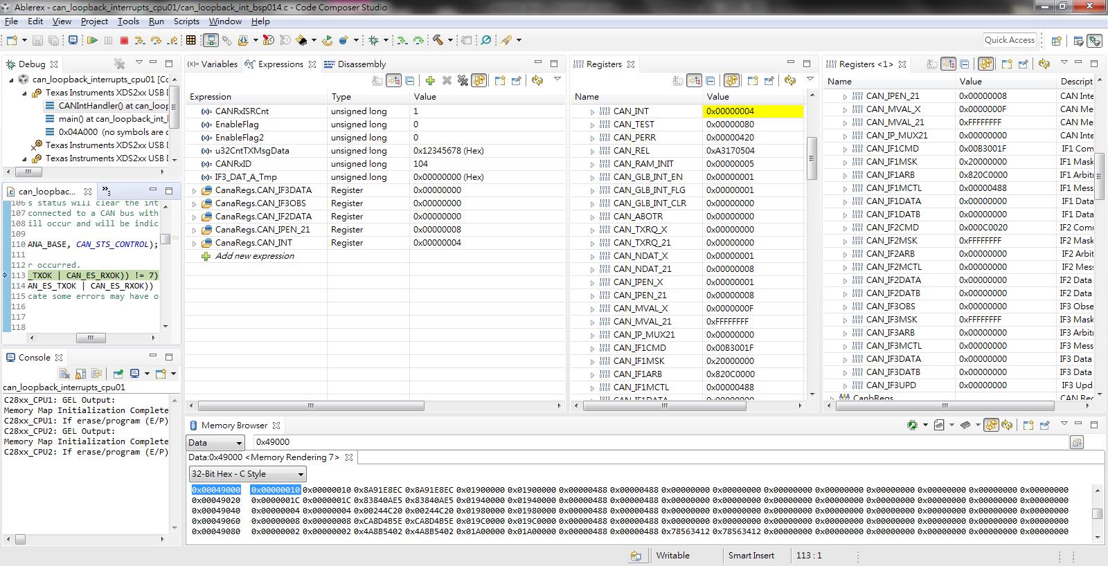
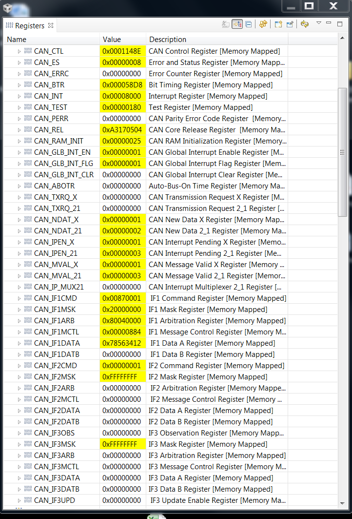
In spruhm8g.pdf, CAN_INT--INT1ID show that
0x01-0x20 Number of message object (mailbox) which caused the interrupt.
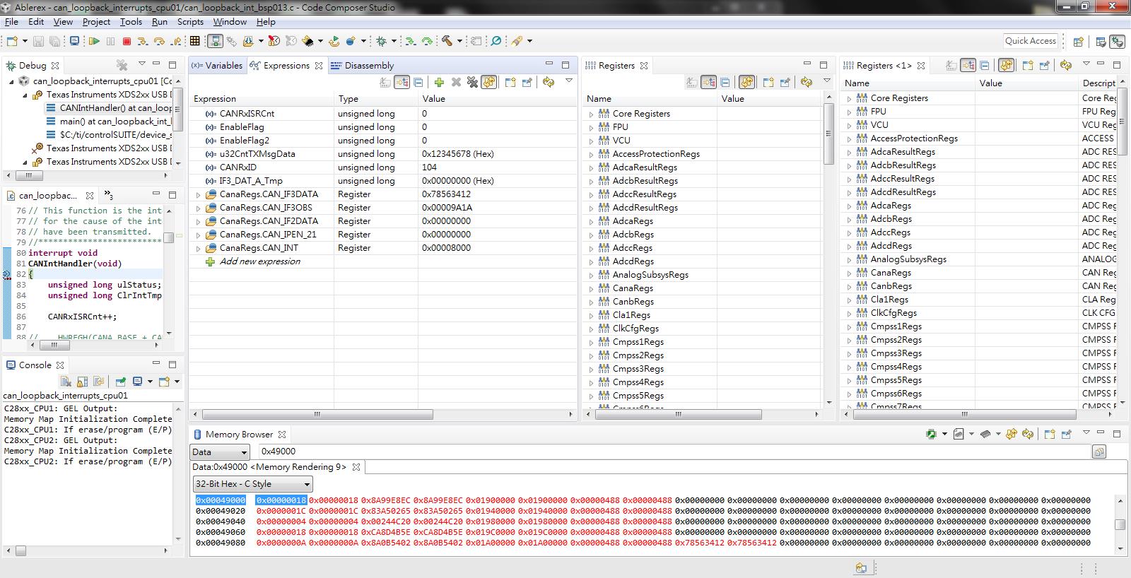
I send a message to CANA mailbox1 from CANB.
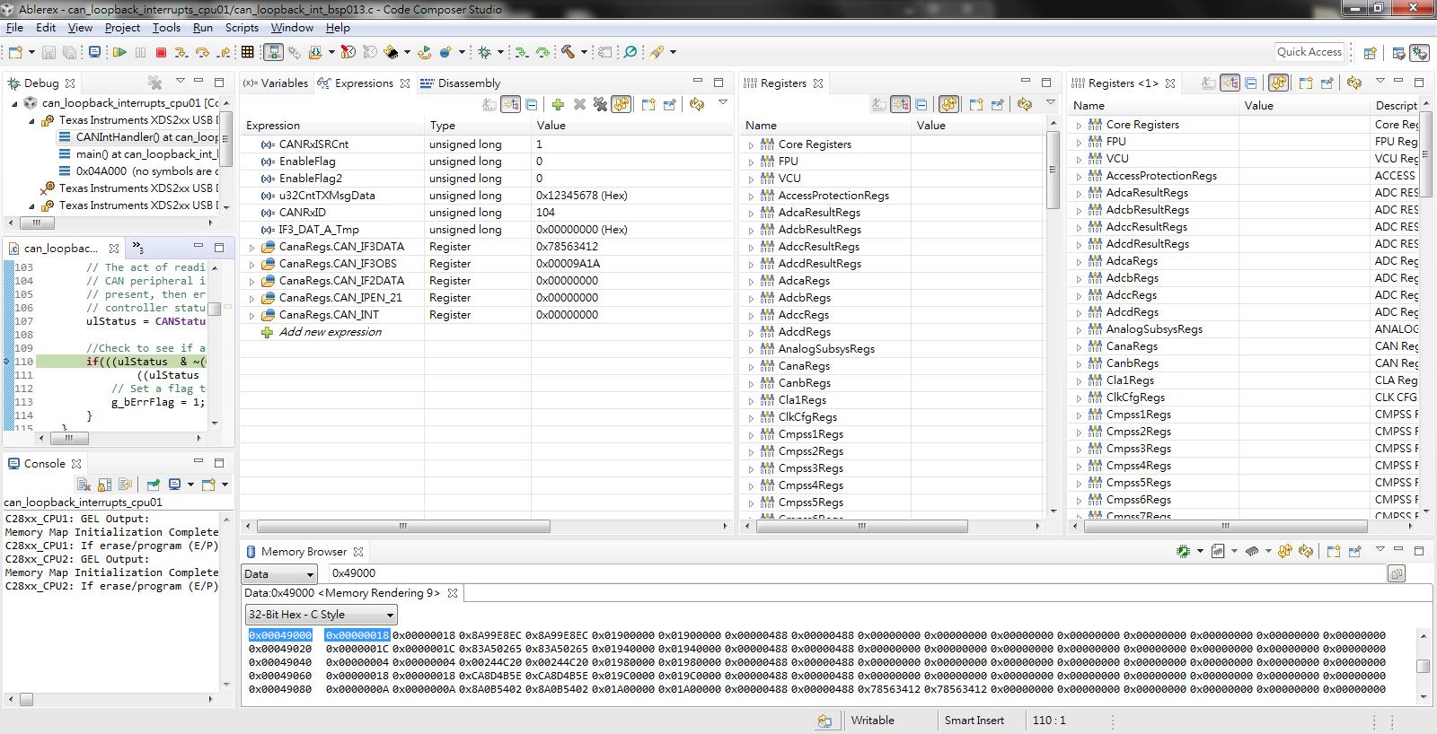
It has a interrupt and the receive data is correct.
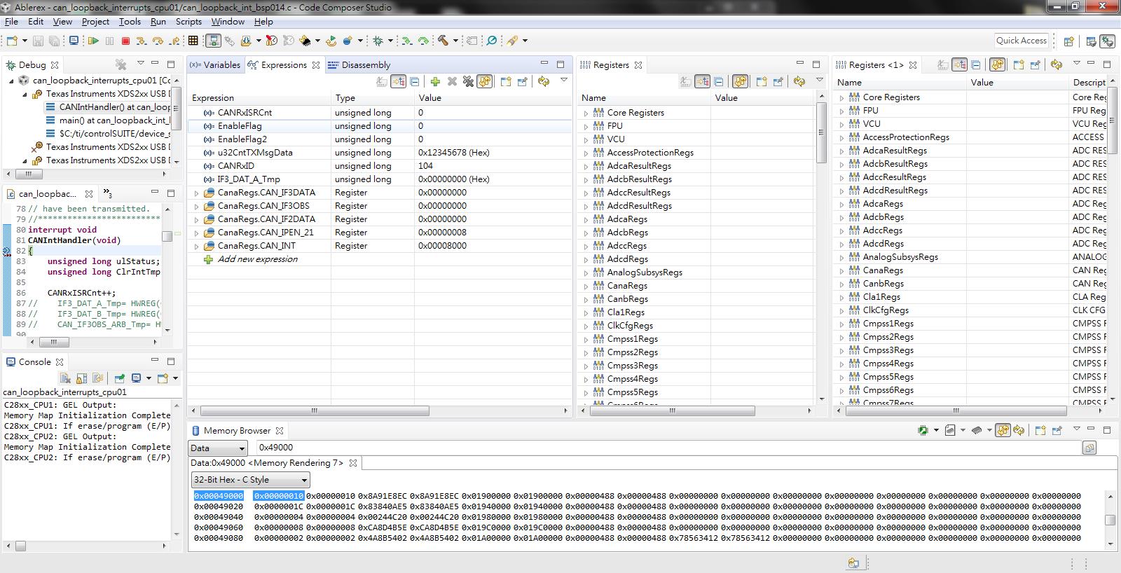
I just see the INT0ID=0x8000,
How to do and know which mailbox cause the interrupt in CAN_INT?

best regards,
Simen