This thread has been locked.

If you have a related question, please click the "Ask a related question" button in the top right corner. The newly created question will be automatically linked to this question.

TMS320F28379D: USB examples from C2000Ware events problems.

Part Number: TMS320F28379D
Other Parts Discussed in Thread: C2000WARE

When using the usb_dev_serial example in the C2000Ware libraries, I am only seeing the USB_EVENT_CONNECTED upon initially starting the software.  In the usb_dev_bulk example, the CONNECTED and DISCONNECTED events happen when the USB cable is plugged and unplugged, as expected.

I saw that this was a bug that was to be addressed, has that happened yet or is there a workaround?

Thanks!

  • Hi Michael,

    I believe I tested this previously and found that I was experiencing both connect and disconnect interrupts.

    What board are you using?

    We will have an engineer look into this.

    Regards,
    sal
  • I am using the F2837x controlCARD R1.3.
  • Hi Michael,

    I tried this and i am also seeing only USB_EVENT_CONNECTED. I am trying to figure out why.

    You can try configuring XINT (an external interrupt) from the toggle of the VBUS pin. If the pin goes high, then set SOFTCONN and if the pin goes low, then clear the SOFTCONN.

    Thanks and Regards
    Harshmeet Singh
  • Any chance you can provide reference code for using XINT in this manner?  Is SOFTCONN a variable, I'm not seeing it defined anywhere?

  • This can go in main()

    //
    // Disconnect and wait for XINT from GPIO46.
    // hack for certification.
    // get USB in known state. although I hacked up USBDBulkInit so it would not connect the PHY
    //
    USBDevDisconnect(USB0_BASE);

    //
    // VBUS interrupt.
    // hack for certification.
    //
    EALLOW;
    PieVectTable.XINT1_INT = &vbus_isr;
    EDIS;
    //
    // Enable XINT1 in the PIE: Group 1 interrupt 4
    //
    PieCtrlRegs.PIECTRL.bit.ENPIE = 1; // Enable the PIE block
    PieCtrlRegs.PIEIER1.bit.INTx4 = 1; // Enable PIE Group 1 INT4
    IER |= M_INT1; // Enable CPU INT1
    //EINT; // Enable Global Interrupts

    //
    //setup GPIO46 for XINT1.
    // hack for certification
    //
    GPIO_SetupXINT1Gpio(46);
    //
    //Configure polarity for XINT1.
    //
    XintRegs.XINT1CR.bit.POLARITY = 3; //positive or negative edge trigger
    //
    //Enable XINT1
    //
    XintRegs.XINT1CR.bit.ENABLE = 1; // Enable XINT1

    //
    // Enable global interrupts
    //
    IntMasterEnable();

    //
    // hack for certification.
    // check if VBUS is high or low at start up because this would not cause an interrupt.
    //
    if(GpioDataRegs.GPBDAT.bit.GPIO46 == 1)
    {
    USBDevConnect(USB0_BASE);
    }
    else
    {
    USBDevDisconnect(USB0_BASE);
    }

    //
    // Main application loop.
    //
    while(1)
    {
    //
    // Nothing to do...everything happens in the interrupt context.
    //
    }
  • Here is the ISR routine:

    //
    // on VBUS toggle connect or disconnect PHY.
    //
    __interrupt void vbus_isr(void)
    {
    if(GpioDataRegs.GPBDAT.bit.GPIO46 == 1)
    {
    USBDevConnect(USB0_BASE);
    }
    else
    {
    USBDevDisconnect(USB0_BASE);
    }

    PieCtrlRegs.PIEACK.all = 0xFFFF;
    }
  • Is it expected that calling USBDevConnect/USBDevDisconnect would cause the USB_EVENT_CONNECTED/USB_EVENT_DISCONNECTED to be fired for the CDC device?
  • It will enable or disable the PHY. and then events should be triggered respectively.

    sal
  • Hello, I am using the 28377d controlcard, and the following problems have occurred.

    [Start: Texas Instruments XDS100v2 USB Debug Probe_0]

    Execute the command:

    %ccs_base%/common/uscif/dbgjtag -f %boarddatafile% -rv -o -F inform,logfile=yes -S pathlength -S integrity

    [Result]


    -----[Print the board config pathname(s)]------------------------------------

    C:\Users\zp\AppData\Local\TEXASI~1\CCS\ti\
    0\0\BrdDat\testBoard.dat

    -----[Print the reset-command software log-file]-----------------------------

    This utility has selected a 100- or 510-class product.
    This utility will load the adapter 'jioserdesusb.dll'.
    The library build date was 'May 23 2017'.
    The library build time was '19:37:36'.
    The library package version is '6.0.628.3'.
    The library component version is '35.35.0.0'.
    The controller does not use a programmable FPGA.
    The controller has a version number of '4' (0x00000004).
    The controller has an insertion length of '0' (0x00000000).
    This utility will attempt to reset the controller.
    This utility has successfully reset the controller.

    -----[Print the reset-command hardware log-file]-----------------------------

    The scan-path will be reset by toggling the JTAG TRST signal.
    The controller is the FTDI FT2232 with USB interface.
    The link from controller to target is direct (without cable).
    The software is configured for FTDI FT2232 features.
    The controller cannot monitor the value on the EMU[0] pin.
    The controller cannot monitor the value on the EMU[1] pin.
    The controller cannot control the timing on output pins.
    The controller cannot control the timing on input pins.
    The scan-path link-delay has been set to exactly '0' (0x0000).

    -----[The log-file for the JTAG TCLK output generated from the PLL]----------

    There is no hardware for programming the JTAG TCLK frequency.

    -----[Measure the source and frequency of the final JTAG TCLKR input]--------

    There is no hardware for measuring the JTAG TCLK frequency.

    -----[Perform the standard path-length test on the JTAG IR and DR]-----------

    This path-length test uses blocks of 64 32-bit words.

    The test for the JTAG IR instruction path-length failed.
    The JTAG IR instruction scan-path is stuck-at-ones.

    The test for the JTAG DR bypass path-length failed.
    The JTAG DR bypass scan-path is stuck-at-ones.

    -----[Perform the Integrity scan-test on the JTAG IR]------------------------

    This test will use blocks of 64 32-bit words.
    This test will be applied just once.

    Do a test using 0xFFFFFFFF.
    Scan tests: 1, skipped: 0, failed: 0
    Do a test using 0x00000000.
    Test 2 Word 0: scanned out 0x00000000 and scanned in 0xFFFFFFFF.
    Test 2 Word 1: scanned out 0x00000000 and scanned in 0xFFFFFFFF.
    Test 2 Word 2: scanned out 0x00000000 and scanned in 0xFFFFFFFF.
    Test 2 Word 3: scanned out 0x00000000 and scanned in 0xFFFFFFFF.
    Test 2 Word 4: scanned out 0x00000000 and scanned in 0xFFFFFFFF.
    Test 2 Word 5: scanned out 0x00000000 and scanned in 0xFFFFFFFF.
    Test 2 Word 6: scanned out 0x00000000 and scanned in 0xFFFFFFFF.
    Test 2 Word 7: scanned out 0x00000000 and scanned in 0xFFFFFFFF.
    The details of the first 8 errors have been provided.
    The utility will now report only the count of failed tests.
    Scan tests: 2, skipped: 0, failed: 1
    Do a test using 0xFE03E0E2.
    Scan tests: 3, skipped: 0, failed: 2
    Do a test using 0x01FC1F1D.
    Scan tests: 4, skipped: 0, failed: 3
    Do a test using 0x5533CCAA.
    Scan tests: 5, skipped: 0, failed: 4
    Do a test using 0xAACC3355.
    Scan tests: 6, skipped: 0, failed: 5
    Some of the values were corrupted - 83.3 percent.

    The JTAG IR Integrity scan-test has failed.

    -----[Perform the Integrity scan-test on the JTAG DR]------------------------

    This test will use blocks of 64 32-bit words.
    This test will be applied just once.

    Do a test using 0xFFFFFFFF.
    Scan tests: 1, skipped: 0, failed: 0
    Do a test using 0x00000000.
    Test 2 Word 0: scanned out 0x00000000 and scanned in 0xFFFFFFFF.
    Test 2 Word 1: scanned out 0x00000000 and scanned in 0xFFFFFFFF.
    Test 2 Word 2: scanned out 0x00000000 and scanned in 0xFFFFFFFF.
    Test 2 Word 3: scanned out 0x00000000 and scanned in 0xFFFFFFFF.
    Test 2 Word 4: scanned out 0x00000000 and scanned in 0xFFFFFFFF.
    Test 2 Word 5: scanned out 0x00000000 and scanned in 0xFFFFFFFF.
    Test 2 Word 6: scanned out 0x00000000 and scanned in 0xFFFFFFFF.
    Test 2 Word 7: scanned out 0x00000000 and scanned in 0xFFFFFFFF.
    The details of the first 8 errors have been provided.
    The utility will now report only the count of failed tests.
    Scan tests: 2, skipped: 0, failed: 1
    Do a test using 0xFE03E0E2.
    Scan tests: 3, skipped: 0, failed: 2
    Do a test using 0x01FC1F1D.
    Scan tests: 4, skipped: 0, failed: 3
    Do a test using 0x5533CCAA.
    Scan tests: 5, skipped: 0, failed: 4
    Do a test using 0xAACC3355.
    Scan tests: 6, skipped: 0, failed: 5
    Some of the values were corrupted - 83.3 percent.

    The JTAG DR Integrity scan-test has failed.

    [End: Texas Instruments XDS100v2 USB Debug Probe_0]

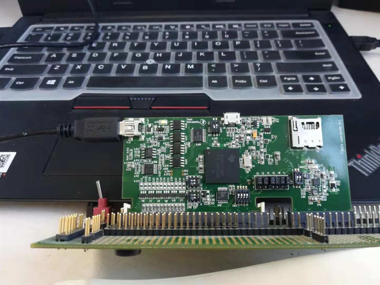
    28377d controlcard and computer connection are as follows

    Device Manager does not appear to have an identifier

    could you tell me how to set it up? 

  • There is a problem with your JTAG connection.

    If you are using the USB 100v2 that is on the controlCARD, then I think your switches are configured properly. But you can try switching theh JTAG/ISO SW1 on the controlCARD.

    Because this post is unrelated to the thread, I recommend you open another forum post to be better assisted.

    sal
  • I do not see the respective events get fired, but when the interrupt fires, I am able to check the status of the GPIO pin and do the appropriate action with USB connect/disconnect.  Thanks for your help!

  • Glad you got it working.

    sal