This thread has been locked.

If you have a related question, please click the "Ask a related question" button in the top right corner. The newly created question will be automatically linked to this question.

CCS/TMS320F28379D: TMS320F28379D

Part Number: TMS320F28379D

Tool/software: Code Composer Studio

I want a WORKING watchdog reset program (NOT INTERRUPT ONE) i am not able to find it in given examples.

In examples there is program for only the WATCHDOG INTERRUPT RESET.

I want my delfino board to reset as the watchdog timer counter overflows.

  • I checked with a colleague and got the following response: "In the workshop the first part of the lab exercise generates a reset and the second part generates an interrupt (i.e. trapped at ESTOP in WAKE 1.8 ISR)"


  • Ashish,

    The Watchdog System and Control Register (SCSR) configures the watchdog to generate a CPU reset or Wake interrupt (ISR at 1.8 in the PIE). To configure this register to generate a reset, bit 1 (WDENINT) needs to be a '0'. So, the code for the bit field header files would look like:

    {
    asm(" EALLOW");
    WdRegs.WDCR.all = 0x0028;
    WdRegs.SCSR.all = 0x0000;
    WdRegs.WDWCR.all = 0x0000;
    asm(" EDIS");
    }

    If using the Driverlib, then the code would look something like:

    {
    SysCtl_setWatchdogMode(SYSCTL_WD_MODE_RESET);
    SysCtl_setWatchdogWindowValue(0);
    SysCtl_enableWatchdog();
    }

    I hope this helps. If this answers your question, please click the green "Verified Answer" button. Thanks.

    - Ken
  • I am able to do as per workshop lab 5 but while i m trying to blink the led again it stuck at InitSysCtrl() function.

    so I am not able to get out of that trap.

    I am uploading my sample code here.

    ###---- MAIN

    #include "F28x_Project.h"
    #include "asd.h"
    #define BLINKY_LED1 34

    void main(void)
    {
    InitSysCtrl();
    InitGpio();
    InitWatchdog();
    GPIO_SetupPinMux(BLINKY_LED1, GPIO_MUX_CPU1, 0);
    GPIO_SetupPinOptions(BLINKY_LED1, GPIO_OUTPUT, GPIO_PUSHPULL);
    GPIO_WritePin(BLINKY_LED1,0);
    DELAY_US(1000*1000);
    GPIO_WritePin(BLINKY_LED1,1);
    DELAY_US(1000*1000);
    //ServiceDog();
    while(1)
    {

    asm(" NOP");
    }
    }

    ###-- Watchdog config

    #include "F28x_Project.h"
    #include "sysctl.h"
    Uint32 loopcount = 0;

    void InitWatchdog(void)
    {

    SysCtl_setWatchdogMode(SYSCTL_WD_MODE_RESET);
    SysCtl_setWatchdogWindowValue(0);
    SysCtl_enableWatchdog();


    /* EALLOW;
    WdRegs.WDCR.all = 0x002F; //Watchdog Timeout period 839.04 ms with 10MHz clk freq.
    WdRegs.SCSR.all = 0x0000; //Reset mode
    WdRegs.WDWCR.all = 0x0000; //
    EDIS;
    */
    }

    Also I am not able to see change the in the registers window.

  • here asd.h is the watchdog configuration file.
  • Ashish,

    It looks like you tried to copy some code from the F2837xd (device_support bit field header files) 'blinky_cpu01.c' example and then modify it with other code around it. You also removed the LED blink code from the loop, so it will only turn on and off once per reset. I also noticed that you are configuring the watchdog to be 'enabled' using the DriverLib (rather than using the header files). As you know, if the watchdog is enabled, then you need to service the watchdog or it will continuously reset the CPU. Do you want to use the bit field header files, DriverLib, or both? It's not clear if you wanted to use both, and if so, then you need to set up your build options for this. (If you are just using DriverLib, then you should have used the Device_init() function rather than InitSysCtrl()). Remember that by default, that the watchdog will perform a reset within approximately 131,000 WDCLK cycles. Could you please provide a CCS screen capture on where you are getting stuck?

    - Ken
  • As you said I am trying to blink led every reset but it is not working as desired.

    How do i service the watchdog ? (using ServiceDog ?)

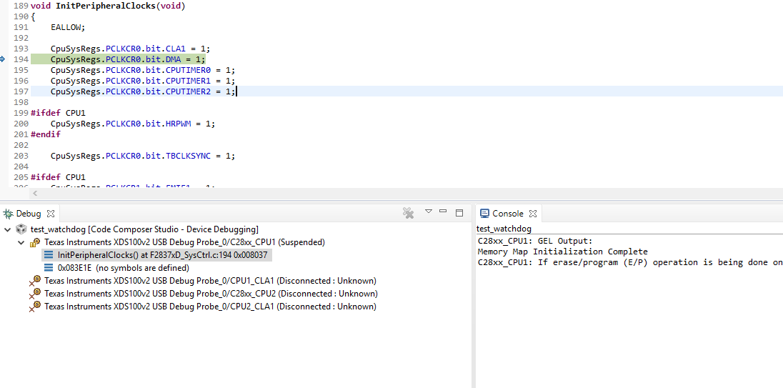
    My program got stuck in  CpuSysRegs.PCLKCR0.bit.DMA = 1; line and cpu is not reseting.

    DeviceInit() is causing underwritten warning

    "

    Description Resource Path Location Type

    #225-D function "Device_init" declared implicitly asd.h /test_watchdog line 25 C/C++ Problem

    "

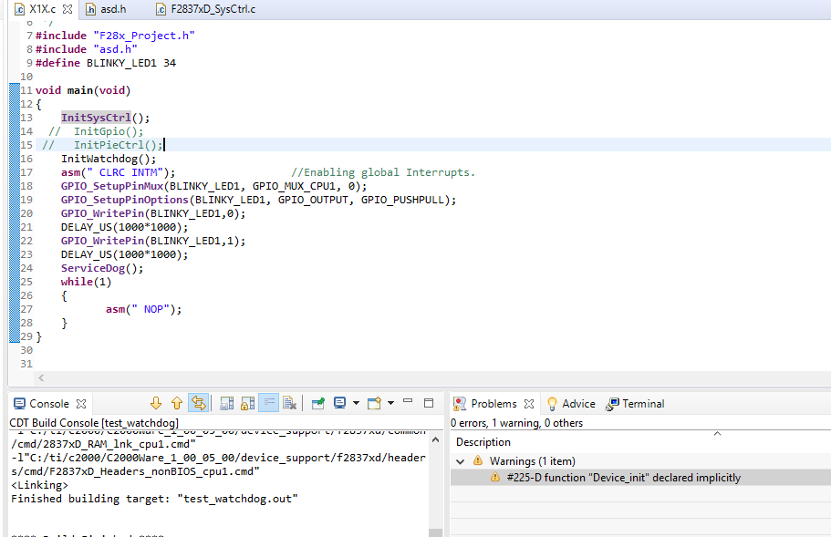
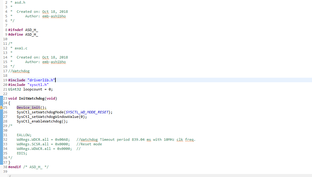
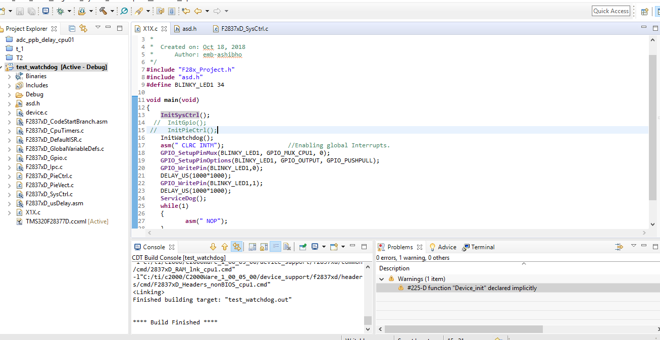
    These are screenshots of my current program.

    1. first screenshot is where my program is stuck.

    2.second screenshot is asd.h (asd.h is watchdog config file.).

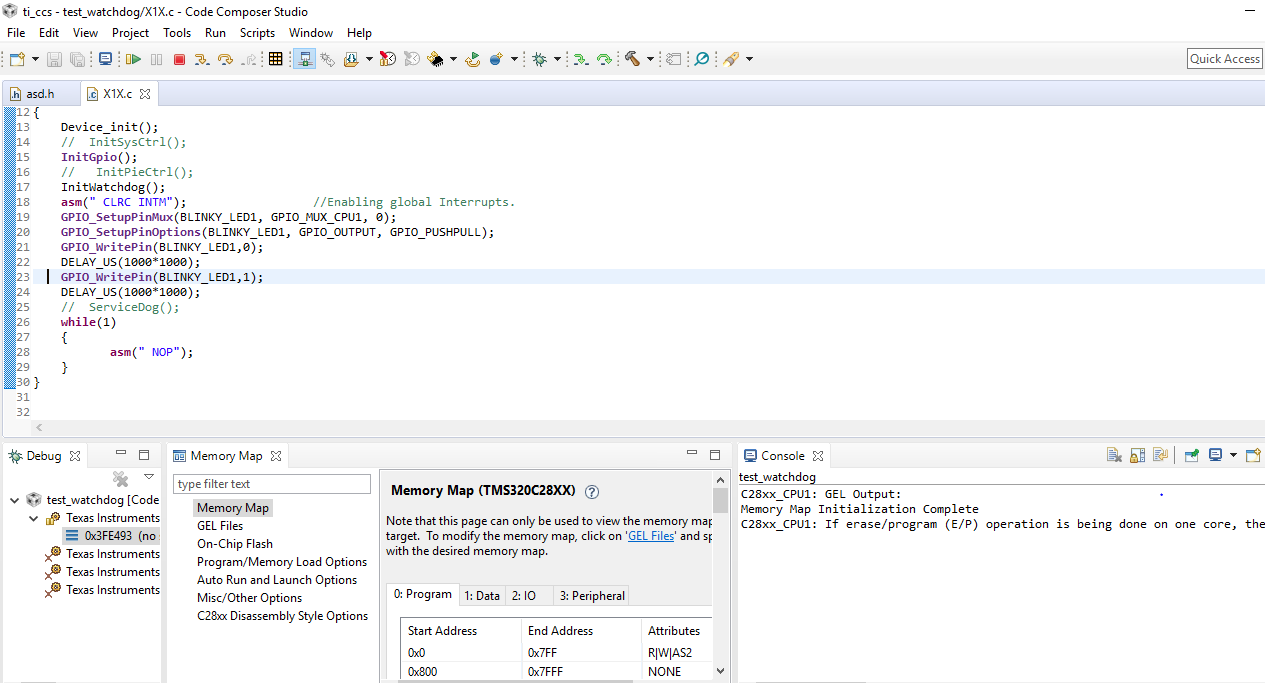
    3.Third is my main program.

    please suggest necessary corrections.

  •  if i do run to line in my while(1) loop then my code open the attached file.I think there is some memory issue.

    Kindly look into it.

  • Ashish,

    It looks like you have a breakpoint set at line 194. Remove the breakpoint or the CPU will stop at this line.

    I hope this helps. If this answers your question, please click the green "Verified Answer" button. Thanks.

    - Ken
  • Ashish,

    You only service the watchdog if you don't want it to reset the MCU. It sounds like you want the watchdog to generate a reset, so you would not service it.

    The reason you are getting a warning that the function is being declared implicitly is because you need declare the function prototype in (e.g. your project .h file). For example:

    extern void Device_init(void);

    Again, it looks like you are mixing the bit field header files and the DriverLib. Is this something that you wanted to do? I suggest reviewing the workshop materials (link is earlier in this thread) to become more familiar with the device. Start with Lab 5.

    I hope this helps. If this answers your question, please click the green "Verified Answer" button. Thanks.

    - Ken
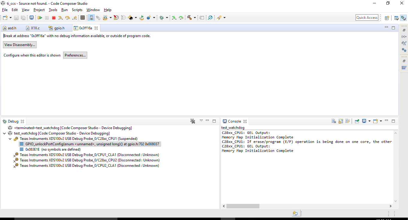
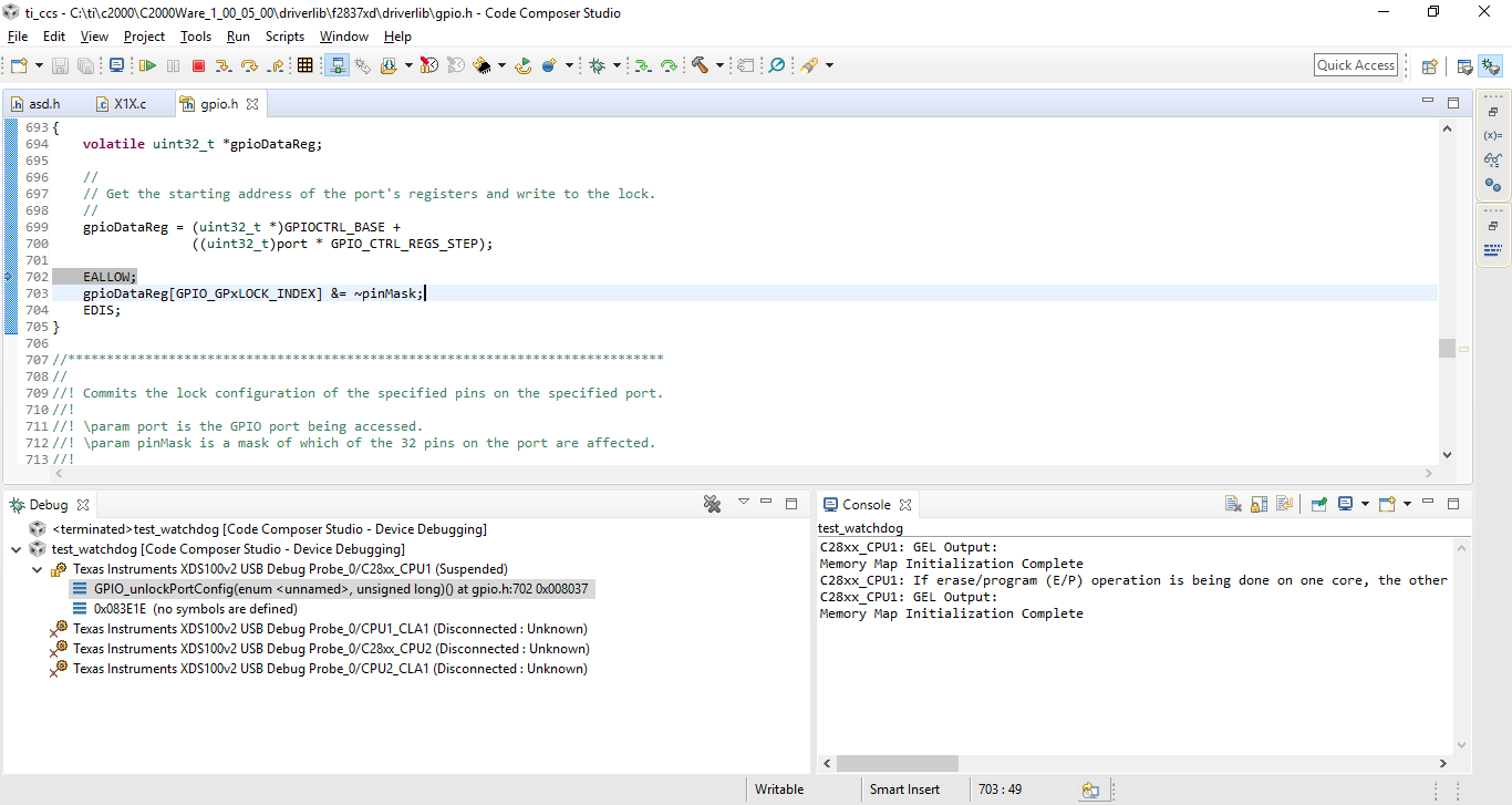
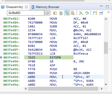
  •    My code is building but i got stuck in debugging it when code come to line 23 in main file(GPIO_WritePin(BLINKY_LED1,1);) and it is giving issue like :- "Break at address "0x3fe493" with no debug information available, or outside of program code."

    Next my program counter is stuck at line 702 line in gpio.h file.

    SCREENSHOT OF ALL ABOVE MENTIONED ISSUE ARE ATTACHED.

  • Ashish,

    The address 0x3fe493 is located in the boot ROM. Did you remember to set the boot mode keys (under Scripts in CCS)?

    - Ken
  • I have tried selecting EMU_BOOT_SARAM(Under script) then it giving address 0x3fe493 issue.
    and When i tried selecting EMU_BOOT_FLASH it is giving {Break at address "0x8038" with no debug information available, or outside of program code.}

    Can you please provide me a working code for watchdog reset .

    1.I want to do watchdog cofiguration in one file.
    2. and in other file i want to blink a led with every reset.

    This is my present code :-
    [
    #include "F28x_Project.h"
    #include "asd.h"
    #define BLINKY_LED1 34

    void main(void)
    {
    Device_init();
    // InitSysCtrl();
    InitGpio();
    // InitPieCtrl();
    InitWatchdog();
    asm(" CLRC INTM"); //Enabling global Interrupts.
    GPIO_SetupPinMux(BLINKY_LED1, GPIO_MUX_CPU1, 0);
    GPIO_SetupPinOptions(BLINKY_LED1, GPIO_OUTPUT, GPIO_PUSHPULL);
    GPIO_WritePin(BLINKY_LED1,0);
    DELAY_US(1000*1000);
    GPIO_WritePin(BLINKY_LED1,1);
    DELAY_US(1000*1000);
    while(1)
    {
    asm(" NOP");
    // ServiceDog();
    }
    }
    ]
  • My program is stopping at ESTOP0 breakpoint.

    memory address is 003fe493.

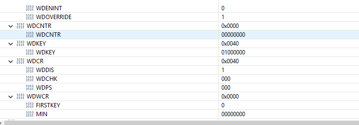
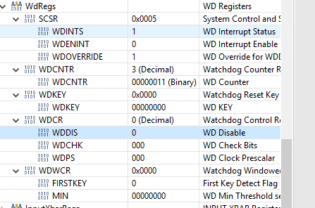
    The watchdog register is starting and counting up untill 3 and then stopping at ESTOP0 breakpoint.

    Values of watchdog register are given below.

  • Watchdog register.

  • Ashish,

    Again, I strongly suggest that you use Lab 5 in the F2837xD workshop to get a better understanding on how the device works. This lab exercise uses the watchdog to generate a reset. The lab code will be easier to work with and then you can try to modify it as needed. The workshop can be found at:

    processors.wiki.ti.com/.../C2000_Multi-Day_Workshop

    Note that when running the F2837xD out of RAM and issuing a hard reset, the RAM blocks are cleared. In lab 5 on page 5-26 (page 112) see step 21. This will explain why the program is being trapped at the ESTOP0 instruction in the boot ROM at 0x3FE493. I am sure this will answer your question.

    I hope this helps. Please click the green "Verified Answer" button to close this thread. Thanks.

    - Ken
  • Sir as you told i have read "In lab 5 on page 5-26 (page 112) see step 21. " so i understand the cause of problem.

    I have tried running lab-5 example but this one also giving same issue as before.

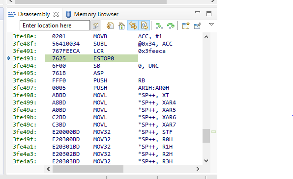
    ISSUE IS --> 3fe493:    7625        ESTOP0    

    I think after hard reset its getting stuck because of ITRAP.  

    I am attaching disassembly photo hereby

    .

  • Ashish,

    Your post is not very clear:

    "I have tried running lab-5 example but this one also giving same issue as before"

    Which one are you referring to? As explained, if you are running the F28379D out of RAM, a hardware reset (generated by the WD) will clear the RAM and as a result you will be trapped at instruction ESTOP0 at 0x3FE493. This will not be the case running out of flash since the flash will copy the code back to the RAM.

    Referenced directly from the workshop Lab 5 exercise:

    "This time we will have the watchdog issue a reset that will toggle the XRSn pin (i.e. perform a hard reset). Now run your code. Where did your code stop? Why did your code stop at an assembly ESTOP0 instruction in the boot ROM at 0x3FE493 and not as we expected at the breakpoint in main( )? Here is what happened. While the code was running, the watchdog timed out and reset the processor. The reset vector was then fetched and the ROM bootloader began execution. Since the device is in emulation boot mode, it read the EMU_KEY and EMU_BMODE values from the PIE RAM which was previously set to RAMM0 boot mode. Again, note that these values do not change and are not affected by reset. When the F28x7x devices undergo a hardware reset (e.g. watchdog reset), the boot ROM code clears the RAM memory blocks. As a result, after the bootloader transferred execution to the beginning of our code at address 0x000000 in RAMM0, the memory block was cleared. The processor was then issued an illegal instruction which trapped us back in the boot ROM.

    This only happened because we are executing out of RAM. In a typical application, the Flash memory contains the program and the reset process would run as we would expect. This should explain why we did not see this behavior with the CCS CPU reset (soft reset where the RAM was not cleared). So what is the advantage of clearing memory during a hardware reset? This ensures that after the reset the original program code and data values will be in a known good state to provide a safer operation. It is important to understand that the watchdog did not behave differently depending on which type of reset was issued. It is the reset process that behaved differently from the different type of resets."

    I hope this helps. Please click the green "Verified Answer" button to close this thread. Thanks.

    - Ken
  • Ashish,

    It's been a while since we have heard from you last. Therefore, we are assuming you were able to resolve your issue. If this isn’t the case, please reject this resolution or reply to this thread. If this thread locks, please make a new thread describing the current status of your issue. Thank you.

    - Ken