Other Parts Discussed in Thread: DRV8303
Tool/software: Code Composer Studio
Hello,
I can't get my motor running on my own designed circuit board. I'm using the TMS320F28069M microcontroller and the DRV8303 gate driver.
Almost everything is the same as the reference design from the F28069M LaunchPad.
The only thing i changed are the PWM channels, SPI and ADC. Here is what the LaunchPad uses for the PWM's:
PWM_AH = ePWM1A
PWM_AL = ePWM1B
PWM_BH = ePWM2A
PWM_BL = ePWM2B
PWM_CH = ePWM3A
PWM_CL = ePWM3B
What i use on my board is:
PWM_AH = ePWM7A
PWM_AL = ePWM7B
PWM_BH = ePWM2A
PWM_BL = ePWM2B
PWM_CH = ePWM1A
PWM_CL = ePWM1B
I'm also using SPIB instead of SPIA.
I've changed the hal.c SPIB registers and the pwmHandle order. I've also changed the ADC feedback order.
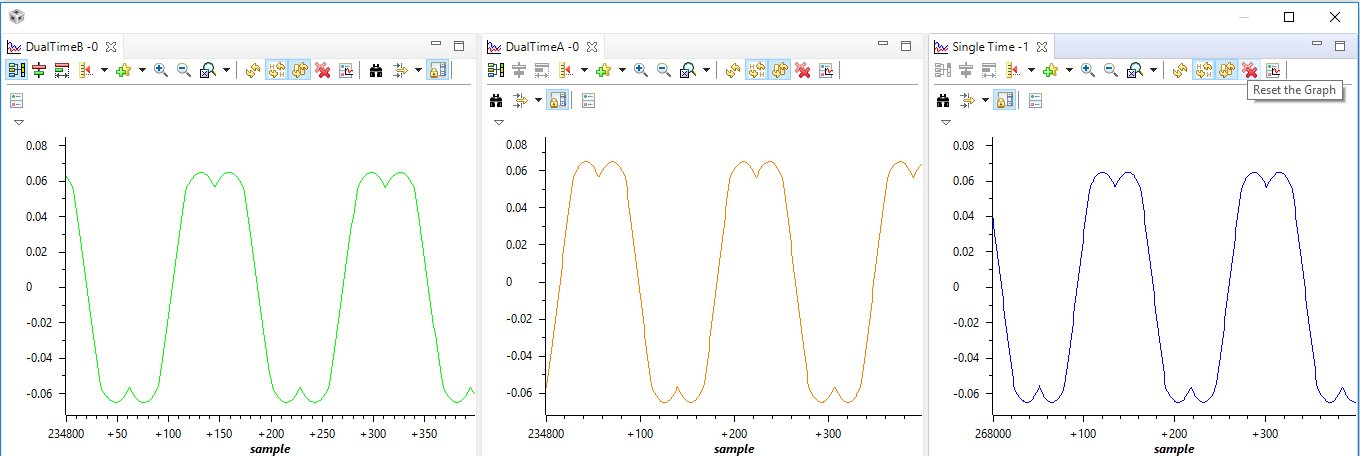
Now when i run the lab01b everything is working. See the graphs below.
I'm using this motor: Nanotec DB42S03
with user.h file:
#ifndef _USER_J1_H_
#define _USER_J1_H_
/* --COPYRIGHT--,BSD
 * Copyright (c) 2012, Texas Instruments Incorporated
 * All rights reserved.
 *
 * Redistribution and use in source and binary forms, with or without
 * modification, are permitted provided that the following conditions
 * are met:
 *
 * *  Redistributions of source code must retain the above copyright
 *    notice, this list of conditions and the following disclaimer.
 *
 * *  Redistributions in binary form must reproduce the above copyright
 *    notice, this list of conditions and the following disclaimer in the
 *    documentation and/or other materials provided with the distribution.
 *
 * *  Neither the name of Texas Instruments Incorporated nor the names of
 *    its contributors may be used to endorse or promote products derived
 *    from this software without specific prior written permission.
 *
 * THIS SOFTWARE IS PROVIDED BY THE COPYRIGHT HOLDERS AND CONTRIBUTORS "AS IS"
 * AND ANY EXPRESS OR IMPLIED WARRANTIES, INCLUDING, BUT NOT LIMITED TO,
 * THE IMPLIED WARRANTIES OF MERCHANTABILITY AND FITNESS FOR A PARTICULAR
 * PURPOSE ARE DISCLAIMED. IN NO EVENT SHALL THE COPYRIGHT OWNER OR
 * CONTRIBUTORS BE LIABLE FOR ANY DIRECT, INDIRECT, INCIDENTAL, SPECIAL,
 * EXEMPLARY, OR CONSEQUENTIAL DAMAGES (INCLUDING, BUT NOT LIMITED TO,
 * PROCUREMENT OF SUBSTITUTE GOODS OR SERVICES; LOSS OF USE, DATA, OR PROFITS;
 * OR BUSINESS INTERRUPTION) HOWEVER CAUSED AND ON ANY THEORY OF LIABILITY,
 * WHETHER IN CONTRACT, STRICT LIABILITY, OR TORT (INCLUDING NEGLIGENCE OR
 * OTHERWISE) ARISING IN ANY WAY OUT OF THE USE OF THIS SOFTWARE,
 * EVEN IF ADVISED OF THE POSSIBILITY OF SUCH DAMAGE.
 * --/COPYRIGHT--*/

//! \file   solutions/instaspin_motion/boards/boostxldrv8301_revB/f28x/f2806xM/src/user_j1.h
//! \brief Contains the public interface for user initialization data for the CTRL, HAL, and EST modules
//!
//! (C) Copyright 2012, Texas Instruments, Inc.


// **************************************************************************
// the includes

//!
//!
//! \defgroup USER USER
//!
//@{


#ifdef __cplusplus
extern "C" {
#endif

// **************************************************************************
// the defines

//! \brief CURRENTS AND VOLTAGES
// **************************************************************************
//! \brief Defines the full scale frequency for IQ variable, Hz
//! \brief All frequencies are converted into (pu) based on the ratio to this value
//! \brief this value MUST be larger than the maximum speed that you are expecting from the motor
#ifndef QEP
#define USER_IQ_FULL_SCALE_FREQ_Hz        (4*USER_VOLTAGE_FILTER_POLE_Hz)   // 800 Example with buffer for 8-pole 6 KRPM motor to be run to 10 KRPM with field weakening; Hz =(RPM * Poles) / 120
#else
#define USER_IQ_FULL_SCALE_FREQ_Hz        (USER_MOTOR_NUM_POLE_PAIRS/0.008)   // (4/0.008) = 500 Example with buffer for 8-pole 6 KRPM motor to be run to 6 KRPM; Hz = (RPM * Poles) / 120
#endif

//! \brief Defines full scale value for the IQ30 variable of Voltage inside the system
//! \brief All voltages are converted into (pu) based on the ratio to this value
//! \brief WARNING: this value MUST meet the following condition: USER_IQ_FULL_SCALE_VOLTAGE_V > 0.5 * USER_MOTOR_MAX_CURRENT * USER_MOTOR_Ls_d * USER_VOLTAGE_FILTER_POLE_rps,
//! \brief WARNING: otherwise the value can saturate and roll-over, causing an inaccurate value
//! \brief WARNING: this value is OFTEN greater than the maximum measured ADC value, especially with high Bemf motors operating at higher than rated speeds
//! \brief WARNING: if you know the value of your Bemf constant, and you know you are operating at a multiple speed due to field weakening, be sure to set this value higher than the expected Bemf voltage
//! \brief It is recommended to start with a value ~3x greater than the USER_ADC_FULL_SCALE_VOLTAGE_V and increase to 4-5x if scenarios where a Bemf calculation may exceed these limits
//! \brief This value is also used to calculate the minimum flux value: USER_IQ_FULL_SCALE_VOLTAGE_V/USER_EST_FREQ_Hz/0.7
#define USER_IQ_FULL_SCALE_VOLTAGE_V      (24.0)   // 24.0 Example for boostxldrv8301_revB typical usage and the Anaheim motor

//! \brief Defines the maximum voltage at the input to the AD converter
//! \brief The value that will be represented by the maximum ADC input (3.3V) and conversion (0FFFh)
//! \brief Hardware dependent, this should be based on the voltage sensing and scaling to the ADC input
#define USER_ADC_FULL_SCALE_VOLTAGE_V       (26.314)      // 26.314 boostxldrv8301_revB voltage scaling

//! \brief Defines the full scale current for the IQ variables, A
//! \brief All currents are converted into (pu) based on the ratio to this value
//! \brief WARNING: this value MUST be larger than the maximum current readings that you are expecting from the motor or the reading will roll over to 0, creating a control issue
#define USER_IQ_FULL_SCALE_CURRENT_A         (20.0) // 20.0 Example for boostxldrv8301_revB typical usage

//! \brief Defines the maximum current at the AD converter
//! \brief The value that will be represented by the maximum ADC input (3.3V) and conversion (0FFFh)
//! \brief Hardware dependent, this should be based on the current sensing and scaling to the ADC input
#define USER_ADC_FULL_SCALE_CURRENT_A        (33.0)  // 33.0 boostxldrv8301_revB current scaling

//! \brief Defines the number of current sensors used
//! \brief Defined by the hardware capability present
//! \brief May be (2) or (3)
#define USER_NUM_CURRENT_SENSORS            (3)   // 3 Preferred setting for best performance across full speed range, allows for 100% duty cycle

//! \brief Defines the number of voltage (phase) sensors
//! \brief Must be (3)
#define USER_NUM_VOLTAGE_SENSORS            (3) // 3 Required

//! \brief ADC current offsets for A, B, and C phases
//! \brief One-time hardware dependent, though the calibration can be done at run-time as well
//! \brief After initial board calibration these values should be updated for your specific hardware so they are available after compile in the binary to be loaded to the controller
#define   I_A_offset    (0.8331743479)
#define   I_B_offset    (0.8355930448)
#define   I_C_offset    (0.8392037153)

//! \brief ADC voltage offsets for A, B, and C phases
//! \brief One-time hardware dependent, though the calibration can be done at run-time as well
//! \brief After initial board calibration these values should be updated for your specific hardware so they are available after compile in the binary to be loaded to the controller
#define   V_A_offset    (0.5271264911)
#define   V_B_offset    (0.5257175565)
#define   V_C_offset    (0.5249399543)


//! \brief CLOCKS & TIMERS
// **************************************************************************
//! \brief Defines the Pulse Width Modulation (PWM) frequency, kHz
//! \brief PWM frequency can be set directly here up to 30 KHz safely (60 KHz MAX in some cases)
//! \brief For higher PWM frequencies (60 KHz+ typical for low inductance, high current ripple motors) it is recommended to use the ePWM hardware
//! \brief and adjustable ADC SOC to decimate the ADC conversion done interrupt to the control system, or to use the software Que example.
//! \brief Otherwise you risk missing interrupts and disrupting the timing of the control state machine
#define USER_PWM_FREQ_kHz                (15.0) //30.0 Example, 8.0 - 30.0 KHz typical; 45-80 KHz may be required for very low inductance, high speed motors

//! \brief Defines the maximum Voltage vector (Vs) magnitude allowed.  This value sets the maximum magnitude for the output of the
//! \brief Id and Iq PI current controllers.  The Id and Iq current controller outputs are Vd and Vq.
//! \brief The relationship between Vs, Vd, and Vq is:  Vs = sqrt(Vd^2 + Vq^2).  In this FOC controller, the
//! \brief Vd value is set equal to USER_MAX_VS_MAG*USER_VD_MAG_FACTOR.  Vq = sqrt(USER_MAX_VS_MAG^2 - Vd^2).
//! \brief Set USER_MAX_VS_MAG = 0.5 for a pure sinewave with a peak at SQRT(3)/2 = 86.6% duty cycle.  No current reconstruction is needed for this scenario.
//! \brief Set USER_MAX_VS_MAG = 1/SQRT(3) = 0.5774 for a pure sinewave with a peak at 100% duty cycle.  Current reconstruction will be needed for this scenario (Lab10a-x).
//! \brief Set USER_MAX_VS_MAG = 2/3 = 0.6666 to create a trapezoidal voltage waveform.  Current reconstruction will be needed for this scenario (Lab10a-x).
//! \brief For space vector over-modulation, see lab 10 for details on system requirements that will allow the SVM generator to go all the way to trapezoidal.
#define USER_MAX_VS_MAG_PU        (0.5)    // Set to 0.5 if a current reconstruction technique is not used.  Look at the module svgen_current in lab10a-x for more info.


//! \brief DECIMATION
// **************************************************************************
//! \brief Defines the number of pwm clock ticks per isr clock tick
//!        Note: Valid values are 1, 2 or 3 only
#define USER_NUM_PWM_TICKS_PER_ISR_TICK        (1)

//! \brief Defines the number of isr ticks (hardware) per controller clock tick (software)
//! \brief Controller clock tick (CTRL) is the main clock used for all timing in the software
//! \brief Typically the PWM Frequency triggers (can be decimated by the ePWM hardware for less overhead) an ADC SOC
//! \brief ADC SOC triggers an ADC Conversion Done
//! \brief ADC Conversion Done triggers ISR
//! \brief This relates the hardware ISR rate to the software controller rate
//! \brief Typcially want to consider some form of decimation (ePWM hardware, CURRENT or EST) over 16KHz ISR to insure interrupt completes and leaves time for background tasks
#define USER_NUM_ISR_TICKS_PER_CTRL_TICK       (1)      // 2 Example, controller clock rate (CTRL) runs at PWM / 2; ex 30 KHz PWM, 15 KHz control

//! \brief Defines the number of controller clock ticks per current controller clock tick
//! \brief Relationship of controller clock rate to current controller (FOC) rate
#define USER_NUM_CTRL_TICKS_PER_CURRENT_TICK   (1)      // 1 Typical, Forward FOC current controller (Iq/Id/IPARK/SVPWM) runs at same rate as CTRL.

//! \brief Defines the number of controller clock ticks per estimator clock tick
//! \brief Relationship of controller clock rate to estimator (FAST) rate
//! \brief Depends on needed dynamic performance, FAST provides very good results as low as 1 KHz while more dynamic or high speed applications may require up to 15 KHz
#define USER_NUM_CTRL_TICKS_PER_EST_TICK       (1)      // 1 Typical, FAST estimator runs at same rate as CTRL;

//! \brief Defines the number of controller clock ticks per speed controller clock tick
//! \brief Relationship of controller clock rate to speed loop rate
#define USER_NUM_CTRL_TICKS_PER_SPEED_TICK  (15)   // 15 Typical to match PWM, ex: 15KHz PWM, controller, and current loop, 1KHz speed loop

//! \brief Defines the number of controller clock ticks per trajectory clock tick
//! \brief Relationship of controller clock rate to trajectory loop rate
//! \brief Typically the same as the speed rate
#define USER_NUM_CTRL_TICKS_PER_TRAJ_TICK   (15)   // 15 Typical to match PWM, ex: 10KHz controller & current loop, 1KHz speed loop, 1 KHz Trajectory


//! \brief LIMITS
// **************************************************************************
//! \brief Defines the maximum negative current to be applied in Id reference
//! \brief Used in field weakening only, this is a safety setting (e.g. to protect against demagnetization)
//! \brief User must also be aware that overall current magnitude [sqrt(Id^2 + Iq^2)] should be kept below any machine design specifications
#define USER_MAX_NEGATIVE_ID_REF_CURRENT_A     (-0.5 * USER_MOTOR_MAX_CURRENT)   // -0.5 * USER_MOTOR_MAX_CURRENT Example, adjust to meet safety needs of your motor

//! \brief Defines the R/L estimation frequency, Hz
//! \brief User higher values for low inductance motors and lower values for higher inductance
//! \brief motors.  The values can range from 100 to 300 Hz.
#define USER_R_OVER_L_EST_FREQ_Hz (200)               // 300 Default

//! \brief Defines the low speed limit for the flux integrator, pu
//! \brief This is the speed range (CW/CCW) at which the ForceAngle object is active, but only if Enabled
//! \brief Outside of this speed - or if Disabled - the ForcAngle will NEVER be active and the angle is provided by FAST only
#define USER_ZEROSPEEDLIMIT   (0.5 / USER_IQ_FULL_SCALE_FREQ_Hz)     // 0.002 pu, 1-5 Hz typical; Hz = USER_ZEROSPEEDLIMIT * USER_IQ_FULL_SCALE_FREQ_Hz

//! \brief Defines the force angle frequency, Hz
//! \brief Frequency of stator vector rotation used by the ForceAngle object
//! \brief Can be positive or negative
#define USER_FORCE_ANGLE_FREQ_Hz   (2.0 * USER_ZEROSPEEDLIMIT * USER_IQ_FULL_SCALE_FREQ_Hz)      // 1.0 Typical force angle start-up speed


//! \brief POLES
// **************************************************************************
//! \brief Defines the analog voltage filter pole location, Hz
//! \brief Must match the hardware filter for Vph
#define USER_VOLTAGE_FILTER_POLE_Hz  (364.682)   // 364.682, value for boostxldrv8301_revB hardware


//! \brief USER MOTOR & ID SETTINGS
// **************************************************************************

//! \brief Defines the default bandwidth for SpinTAC Control
//! \brief This value should be determined by putting SpinTAC Control through a tuning process
//! \brief If a Bandwidth Scale value has been previously identified
//! \brief multiply it by 20 to convert into Bandwidth
//#define USER_SYSTEM_BANDWIDTH      (10.0)

//! \brief Define each motor with a unique name and ID number
// BLDC & SMPM motors
#define Estun_EMJ_04APB22           101
#define Anaheim_BLY172S             102
#define Tamagawa_A0100              103
#define Teknic_M2310PLN04K          104
#define MY_MOTOR                    113

// IPM motors
// If user provides separate Ls-d, Ls-q
// else treat as SPM with user or identified average Ls
#define Belt_Drive_Washer_IPM       201

// ACIM motors
#define Marathon_5K33GN2A           301

//! \brief Uncomment the motor which should be included at compile
//! \brief These motor ID settings and motor parameters are then available to be used by the control system
//! \brief Once your ideal settings and parameters are identified update the motor section here so it is available in the binary code
//#define USER_MOTOR Estun_EMJ_04APB22
//#define USER_MOTOR Anaheim_BLY172S
//#define USER_MOTOR Tamagawa_A0100
//#define USER_MOTOR Teknic_M2310PLN04K
//#define USER_MOTOR Belt_Drive_Washer_IPM
//#define USER_MOTOR Marathon_5K33GN2A
#define USER_MOTOR MY_MOTOR


#elif (USER_MOTOR == MY_MOTOR)
#define USER_MOTOR_TYPE                 MOTOR_Type_Pm
#define USER_MOTOR_NUM_POLE_PAIRS       (4)
#define USER_MOTOR_Rr                   (NULL)
#define USER_MOTOR_Rs                   (NULL)
#define USER_MOTOR_Ls_d                 (NULL)
#define USER_MOTOR_Ls_q                 (NULL7)
#define USER_MOTOR_RATED_FLUX           (NULL)
#define USER_MOTOR_MAGNETIZING_CURRENT  (NULL)
#define USER_MOTOR_RES_EST_CURRENT      (1.0)
#define USER_MOTOR_IND_EST_CURRENT      (-1.0)
#define USER_MOTOR_MAX_CURRENT          (3.0)
#define USER_MOTOR_FLUX_EST_FREQ_Hz     (20.0)


#else
#error No motor type specified
#endif

#ifdef __cplusplus
}
#endif // extern "C"

//@} // ingroup
#endif // end of _USER_J1_H_ definition
Here is the hal.c file i use:
/* --COPYRIGHT--,BSD
* Copyright (c) 2012, Texas Instruments Incorporated
* All rights reserved.
*
* Redistribution and use in source and binary forms, with or without
* modification, are permitted provided that the following conditions
* are met:
*
* * Redistributions of source code must retain the above copyright
* notice, this list of conditions and the following disclaimer.
*
* * Redistributions in binary form must reproduce the above copyright
* notice, this list of conditions and the following disclaimer in the
* documentation and/or other materials provided with the distribution.
*
* * Neither the name of Texas Instruments Incorporated nor the names of
* its contributors may be used to endorse or promote products derived
* from this software without specific prior written permission.
*
* THIS SOFTWARE IS PROVIDED BY THE COPYRIGHT HOLDERS AND CONTRIBUTORS "AS IS"
* AND ANY EXPRESS OR IMPLIED WARRANTIES, INCLUDING, BUT NOT LIMITED TO,
* THE IMPLIED WARRANTIES OF MERCHANTABILITY AND FITNESS FOR A PARTICULAR
* PURPOSE ARE DISCLAIMED. IN NO EVENT SHALL THE COPYRIGHT OWNER OR
* CONTRIBUTORS BE LIABLE FOR ANY DIRECT, INDIRECT, INCIDENTAL, SPECIAL,
* EXEMPLARY, OR CONSEQUENTIAL DAMAGES (INCLUDING, BUT NOT LIMITED TO,
* PROCUREMENT OF SUBSTITUTE GOODS OR SERVICES; LOSS OF USE, DATA, OR PROFITS;
* OR BUSINESS INTERRUPTION) HOWEVER CAUSED AND ON ANY THEORY OF LIABILITY,
* WHETHER IN CONTRACT, STRICT LIABILITY, OR TORT (INCLUDING NEGLIGENCE OR
* OTHERWISE) ARISING IN ANY WAY OUT OF THE USE OF THIS SOFTWARE,
* EVEN IF ADVISED OF THE POSSIBILITY OF SUCH DAMAGE.
* --/COPYRIGHT--*/
//! \file solutions/instaspin_foc/boards/drv8301kit_revD/f28x/f2806xF/src/hal.c
//! \brief Contains the various functions related to the HAL object (everything outside the CTRL system)
//!
//! (C) Copyright 2011, Texas Instruments, Inc.
// **************************************************************************
// the includes
// drivers
// modules
// platforms
#include "hal.h"
#include "user.h"
#include "hal_obj.h"
#ifdef FLASH
#pragma CODE_SECTION(HAL_setupFlash,"ramfuncs");
#endif
// **************************************************************************
// the defines
#define US_TO_CNT(A) ((((long double) A * (long double)USER_SYSTEM_FREQ_MHz) - 9.0L) / 5.0L)
// **************************************************************************
// the globals
HAL_Obj hal;
// **************************************************************************
// the functions
void HAL_cal(HAL_Handle handle)
{
HAL_Obj *obj = (HAL_Obj *)handle;
// enable the ADC clock
CLK_enableAdcClock(obj->clkHandle);
// Run the Device_cal() function
// This function copies the ADC and oscillator calibration values from TI reserved
// OTP into the appropriate trim registers
// This boot ROM automatically calls this function to calibrate the interal
// oscillators and ADC with device specific calibration data.
// If the boot ROM is bypassed by Code Composer Studio during the development process,
// then the calibration must be initialized by the application
ENABLE_PROTECTED_REGISTER_WRITE_MODE;
(*Device_cal)();
DISABLE_PROTECTED_REGISTER_WRITE_MODE;
// run offsets calibration in user's memory
HAL_AdcOffsetSelfCal(handle);
// run oscillator compensation
HAL_OscTempComp(handle);
// disable the ADC clock
CLK_disableAdcClock(obj->clkHandle);
return;
} // end of HAL_cal() function
void HAL_OscTempComp(HAL_Handle handle)
{
HAL_Obj *obj = (HAL_Obj *)handle;
uint16_t Temperature;
// disable the ADCs
ADC_disable(obj->adcHandle);
// power up the bandgap circuit
ADC_enableBandGap(obj->adcHandle);
// set the ADC voltage reference source to internal
ADC_setVoltRefSrc(obj->adcHandle,ADC_VoltageRefSrc_Int);
// enable the ADC reference buffers
ADC_enableRefBuffers(obj->adcHandle);
// Set main clock scaling factor (max45MHz clock for the ADC module)
ADC_setDivideSelect(obj->adcHandle,ADC_DivideSelect_ClkIn_by_2);
// power up the ADCs
ADC_powerUp(obj->adcHandle);
// enable the ADCs
ADC_enable(obj->adcHandle);
// enable non-overlap mode
ADC_enableNoOverlapMode(obj->adcHandle);
// connect channel A5 internally to the temperature sensor
ADC_setTempSensorSrc(obj->adcHandle, ADC_TempSensorSrc_Int);
// set SOC0 channel select to ADCINA5
ADC_setSocChanNumber(obj->adcHandle, ADC_SocNumber_0, ADC_SocChanNumber_A5);
// set SOC0 acquisition period to 26 ADCCLK
ADC_setSocSampleDelay(obj->adcHandle, ADC_SocNumber_0, ADC_SocSampleDelay_64_cycles);
// connect ADCINT1 to EOC0
ADC_setIntSrc(obj->adcHandle, ADC_IntNumber_1, ADC_IntSrc_EOC0);
// clear ADCINT1 flag
ADC_clearIntFlag(obj->adcHandle, ADC_IntNumber_1);
// enable ADCINT1
ADC_enableInt(obj->adcHandle, ADC_IntNumber_1);
// force start of conversion on SOC0
ADC_setSocFrc(obj->adcHandle, ADC_SocFrc_0);
// wait for end of conversion
while (ADC_getIntFlag(obj->adcHandle, ADC_IntNumber_1) == 0){}
// clear ADCINT1 flag
ADC_clearIntFlag(obj->adcHandle, ADC_IntNumber_1);
Temperature = ADC_readResult(obj->adcHandle, ADC_ResultNumber_0);
HAL_osc1Comp(handle, Temperature);
HAL_osc2Comp(handle, Temperature);
return;
} // end of HAL_OscTempComp() function
void HAL_osc1Comp(HAL_Handle handle, const int16_t sensorSample)
{
int16_t compOscFineTrim;
HAL_Obj *obj = (HAL_Obj *)handle;
ENABLE_PROTECTED_REGISTER_WRITE_MODE;
compOscFineTrim = ((sensorSample - getRefTempOffset())*(int32_t)getOsc1FineTrimSlope()
+ OSC_POSTRIM_OFF + FP_ROUND )/FP_SCALE + getOsc1FineTrimOffset() - OSC_POSTRIM;
if(compOscFineTrim > 31)
{
compOscFineTrim = 31;
}
else if(compOscFineTrim < -31)
{
compOscFineTrim = -31;
}
OSC_setTrim(obj->oscHandle, OSC_Number_1, HAL_getOscTrimValue(getOsc1CoarseTrim(), compOscFineTrim));
DISABLE_PROTECTED_REGISTER_WRITE_MODE;
return;
} // end of HAL_osc1Comp() function
void HAL_osc2Comp(HAL_Handle handle, const int16_t sensorSample)
{
int16_t compOscFineTrim;
HAL_Obj *obj = (HAL_Obj *)handle;
ENABLE_PROTECTED_REGISTER_WRITE_MODE;
compOscFineTrim = ((sensorSample - getRefTempOffset())*(int32_t)getOsc2FineTrimSlope()
+ OSC_POSTRIM_OFF + FP_ROUND )/FP_SCALE + getOsc2FineTrimOffset() - OSC_POSTRIM;
if(compOscFineTrim > 31)
{
compOscFineTrim = 31;
}
else if(compOscFineTrim < -31)
{
compOscFineTrim = -31;
}
OSC_setTrim(obj->oscHandle, OSC_Number_2, HAL_getOscTrimValue(getOsc2CoarseTrim(), compOscFineTrim));
DISABLE_PROTECTED_REGISTER_WRITE_MODE;
return;
} // end of HAL_osc2Comp() function
uint16_t HAL_getOscTrimValue(int16_t coarse, int16_t fine)
{
uint16_t regValue = 0;
if(fine < 0)
{
regValue = ((-fine) | 0x20) << 9;
}
else
{
regValue = fine << 9;
}
if(coarse < 0)
{
regValue |= ((-coarse) | 0x80);
}
else
{
regValue |= coarse;
}
return regValue;
} // end of HAL_getOscTrimValue() function
void HAL_AdcOffsetSelfCal(HAL_Handle handle)
{
HAL_Obj *obj = (HAL_Obj *)handle;
uint16_t AdcConvMean;
// disable the ADCs
ADC_disable(obj->adcHandle);
// power up the bandgap circuit
ADC_enableBandGap(obj->adcHandle);
// set the ADC voltage reference source to internal
ADC_setVoltRefSrc(obj->adcHandle,ADC_VoltageRefSrc_Int);
// enable the ADC reference buffers
ADC_enableRefBuffers(obj->adcHandle);
// Set main clock scaling factor (max45MHz clock for the ADC module)
ADC_setDivideSelect(obj->adcHandle,ADC_DivideSelect_ClkIn_by_2);
// power up the ADCs
ADC_powerUp(obj->adcHandle);
// enable the ADCs
ADC_enable(obj->adcHandle);
//Select VREFLO internal connection on B5
ADC_enableVoltRefLoConv(obj->adcHandle);
//Select channel B5 for all SOC
HAL_AdcCalChanSelect(handle, ADC_SocChanNumber_B5);
//Apply artificial offset (+80) to account for a negative offset that may reside in the ADC core
ADC_setOffTrim(obj->adcHandle, 80);
//Capture ADC conversion on VREFLO
AdcConvMean = HAL_AdcCalConversion(handle);
//Set offtrim register with new value (i.e remove artical offset (+80) and create a two's compliment of the offset error)
ADC_setOffTrim(obj->adcHandle, 80 - AdcConvMean);
//Select external ADCIN5 input pin on B5
ADC_disableVoltRefLoConv(obj->adcHandle);
return;
} // end of HAL_AdcOffsetSelfCal() function
void HAL_AdcCalChanSelect(HAL_Handle handle, const ADC_SocChanNumber_e chanNumber)
{
HAL_Obj *obj = (HAL_Obj *)handle;
ADC_setSocChanNumber(obj->adcHandle,ADC_SocNumber_0,chanNumber);
ADC_setSocChanNumber(obj->adcHandle,ADC_SocNumber_1,chanNumber);
ADC_setSocChanNumber(obj->adcHandle,ADC_SocNumber_2,chanNumber);
ADC_setSocChanNumber(obj->adcHandle,ADC_SocNumber_3,chanNumber);
ADC_setSocChanNumber(obj->adcHandle,ADC_SocNumber_4,chanNumber);
ADC_setSocChanNumber(obj->adcHandle,ADC_SocNumber_5,chanNumber);
ADC_setSocChanNumber(obj->adcHandle,ADC_SocNumber_6,chanNumber);
ADC_setSocChanNumber(obj->adcHandle,ADC_SocNumber_7,chanNumber);
ADC_setSocChanNumber(obj->adcHandle,ADC_SocNumber_8,chanNumber);
ADC_setSocChanNumber(obj->adcHandle,ADC_SocNumber_9,chanNumber);
ADC_setSocChanNumber(obj->adcHandle,ADC_SocNumber_10,chanNumber);
ADC_setSocChanNumber(obj->adcHandle,ADC_SocNumber_11,chanNumber);
ADC_setSocChanNumber(obj->adcHandle,ADC_SocNumber_12,chanNumber);
ADC_setSocChanNumber(obj->adcHandle,ADC_SocNumber_13,chanNumber);
ADC_setSocChanNumber(obj->adcHandle,ADC_SocNumber_14,chanNumber);
ADC_setSocChanNumber(obj->adcHandle,ADC_SocNumber_15,chanNumber);
return;
} // end of HAL_AdcCalChanSelect() function
uint16_t HAL_AdcCalConversion(HAL_Handle handle)
{
HAL_Obj *obj = (HAL_Obj *)handle;
uint16_t index, SampleSize, Mean;
uint32_t Sum;
ADC_SocSampleDelay_e ACQPS_Value;
index = 0; //initialize index to 0
SampleSize = 256; //set sample size to 256 (**NOTE: Sample size must be multiples of 2^x where is an integer >= 4)
Sum = 0; //set sum to 0
Mean = 999; //initialize mean to known value
//Set the ADC sample window to the desired value (Sample window = ACQPS + 1)
ACQPS_Value = ADC_SocSampleDelay_7_cycles;
ADC_setSocSampleDelay(obj->adcHandle,ADC_SocNumber_0,ACQPS_Value);
ADC_setSocSampleDelay(obj->adcHandle,ADC_SocNumber_1,ACQPS_Value);
ADC_setSocSampleDelay(obj->adcHandle,ADC_SocNumber_2,ACQPS_Value);
ADC_setSocSampleDelay(obj->adcHandle,ADC_SocNumber_3,ACQPS_Value);
ADC_setSocSampleDelay(obj->adcHandle,ADC_SocNumber_4,ACQPS_Value);
ADC_setSocSampleDelay(obj->adcHandle,ADC_SocNumber_5,ACQPS_Value);
ADC_setSocSampleDelay(obj->adcHandle,ADC_SocNumber_6,ACQPS_Value);
ADC_setSocSampleDelay(obj->adcHandle,ADC_SocNumber_7,ACQPS_Value);
ADC_setSocSampleDelay(obj->adcHandle,ADC_SocNumber_8,ACQPS_Value);
ADC_setSocSampleDelay(obj->adcHandle,ADC_SocNumber_9,ACQPS_Value);
ADC_setSocSampleDelay(obj->adcHandle,ADC_SocNumber_10,ACQPS_Value);
ADC_setSocSampleDelay(obj->adcHandle,ADC_SocNumber_11,ACQPS_Value);
ADC_setSocSampleDelay(obj->adcHandle,ADC_SocNumber_12,ACQPS_Value);
ADC_setSocSampleDelay(obj->adcHandle,ADC_SocNumber_13,ACQPS_Value);
ADC_setSocSampleDelay(obj->adcHandle,ADC_SocNumber_14,ACQPS_Value);
ADC_setSocSampleDelay(obj->adcHandle,ADC_SocNumber_15,ACQPS_Value);
// Enabled ADCINT1 and ADCINT2
ADC_enableInt(obj->adcHandle, ADC_IntNumber_1);
ADC_enableInt(obj->adcHandle, ADC_IntNumber_2);
// Disable continuous sampling for ADCINT1 and ADCINT2
ADC_setIntMode(obj->adcHandle, ADC_IntNumber_1, ADC_IntMode_EOC);
ADC_setIntMode(obj->adcHandle, ADC_IntNumber_2, ADC_IntMode_EOC);
//ADCINTs trigger at end of conversion
ADC_setIntPulseGenMode(obj->adcHandle, ADC_IntPulseGenMode_Prior);
// Setup ADCINT1 and ADCINT2 trigger source
ADC_setIntSrc(obj->adcHandle, ADC_IntNumber_1, ADC_IntSrc_EOC6);
ADC_setIntSrc(obj->adcHandle, ADC_IntNumber_2, ADC_IntSrc_EOC14);
// Setup each SOC's ADCINT trigger source
ADC_setupSocTrigSrc(obj->adcHandle, ADC_SocNumber_0, ADC_Int2TriggersSOC);
ADC_setupSocTrigSrc(obj->adcHandle, ADC_SocNumber_1, ADC_Int2TriggersSOC);
ADC_setupSocTrigSrc(obj->adcHandle, ADC_SocNumber_2, ADC_Int2TriggersSOC);
ADC_setupSocTrigSrc(obj->adcHandle, ADC_SocNumber_3, ADC_Int2TriggersSOC);
ADC_setupSocTrigSrc(obj->adcHandle, ADC_SocNumber_4, ADC_Int2TriggersSOC);
ADC_setupSocTrigSrc(obj->adcHandle, ADC_SocNumber_5, ADC_Int2TriggersSOC);
ADC_setupSocTrigSrc(obj->adcHandle, ADC_SocNumber_6, ADC_Int2TriggersSOC);
ADC_setupSocTrigSrc(obj->adcHandle, ADC_SocNumber_7, ADC_Int2TriggersSOC);
ADC_setupSocTrigSrc(obj->adcHandle, ADC_SocNumber_8, ADC_Int1TriggersSOC);
ADC_setupSocTrigSrc(obj->adcHandle, ADC_SocNumber_9, ADC_Int1TriggersSOC);
ADC_setupSocTrigSrc(obj->adcHandle, ADC_SocNumber_10, ADC_Int1TriggersSOC);
ADC_setupSocTrigSrc(obj->adcHandle, ADC_SocNumber_11, ADC_Int1TriggersSOC);
ADC_setupSocTrigSrc(obj->adcHandle, ADC_SocNumber_12, ADC_Int1TriggersSOC);
ADC_setupSocTrigSrc(obj->adcHandle, ADC_SocNumber_13, ADC_Int1TriggersSOC);
ADC_setupSocTrigSrc(obj->adcHandle, ADC_SocNumber_14, ADC_Int1TriggersSOC);
ADC_setupSocTrigSrc(obj->adcHandle, ADC_SocNumber_15, ADC_Int1TriggersSOC);
// Delay before converting ADC channels
usDelay(US_TO_CNT(ADC_DELAY_usec));
ADC_setSocFrcWord(obj->adcHandle, 0x00FF);
while( index < SampleSize )
{
//Wait for ADCINT1 to trigger, then add ADCRESULT0-7 registers to sum
while (ADC_getIntFlag(obj->adcHandle, ADC_IntNumber_1) == 0){}
//Must clear ADCINT1 flag since INT1CONT = 0
ADC_clearIntFlag(obj->adcHandle, ADC_IntNumber_1);
Sum += ADC_readResult(obj->adcHandle, ADC_ResultNumber_0);
Sum += ADC_readResult(obj->adcHandle, ADC_ResultNumber_1);
Sum += ADC_readResult(obj->adcHandle, ADC_ResultNumber_2);
Sum += ADC_readResult(obj->adcHandle, ADC_ResultNumber_3);
Sum += ADC_readResult(obj->adcHandle, ADC_ResultNumber_4);
Sum += ADC_readResult(obj->adcHandle, ADC_ResultNumber_5);
Sum += ADC_readResult(obj->adcHandle, ADC_ResultNumber_6);
Sum += ADC_readResult(obj->adcHandle, ADC_ResultNumber_7);
//Wait for ADCINT2 to trigger, then add ADCRESULT8-15 registers to sum
while (ADC_getIntFlag(obj->adcHandle, ADC_IntNumber_2) == 0){}
//Must clear ADCINT2 flag since INT2CONT = 0
ADC_clearIntFlag(obj->adcHandle, ADC_IntNumber_2);
Sum += ADC_readResult(obj->adcHandle, ADC_ResultNumber_8);
Sum += ADC_readResult(obj->adcHandle, ADC_ResultNumber_9);
Sum += ADC_readResult(obj->adcHandle, ADC_ResultNumber_10);
Sum += ADC_readResult(obj->adcHandle, ADC_ResultNumber_11);
Sum += ADC_readResult(obj->adcHandle, ADC_ResultNumber_12);
Sum += ADC_readResult(obj->adcHandle, ADC_ResultNumber_13);
Sum += ADC_readResult(obj->adcHandle, ADC_ResultNumber_14);
Sum += ADC_readResult(obj->adcHandle, ADC_ResultNumber_15);
index+=16;
} // end data collection
//Disable ADCINT1 and ADCINT2 to STOP the ping-pong sampling
ADC_disableInt(obj->adcHandle, ADC_IntNumber_1);
ADC_disableInt(obj->adcHandle, ADC_IntNumber_2);
//Calculate average ADC sample value
Mean = Sum / SampleSize;
// Clear start of conversion trigger
ADC_setupSocTrigSrc(obj->adcHandle, ADC_SocNumber_0, ADC_NoIntTriggersSOC);
ADC_setupSocTrigSrc(obj->adcHandle, ADC_SocNumber_1, ADC_NoIntTriggersSOC);
ADC_setupSocTrigSrc(obj->adcHandle, ADC_SocNumber_2, ADC_NoIntTriggersSOC);
ADC_setupSocTrigSrc(obj->adcHandle, ADC_SocNumber_3, ADC_NoIntTriggersSOC);
ADC_setupSocTrigSrc(obj->adcHandle, ADC_SocNumber_4, ADC_NoIntTriggersSOC);
ADC_setupSocTrigSrc(obj->adcHandle, ADC_SocNumber_5, ADC_NoIntTriggersSOC);
ADC_setupSocTrigSrc(obj->adcHandle, ADC_SocNumber_6, ADC_NoIntTriggersSOC);
ADC_setupSocTrigSrc(obj->adcHandle, ADC_SocNumber_7, ADC_NoIntTriggersSOC);
ADC_setupSocTrigSrc(obj->adcHandle, ADC_SocNumber_8, ADC_NoIntTriggersSOC);
ADC_setupSocTrigSrc(obj->adcHandle, ADC_SocNumber_9, ADC_NoIntTriggersSOC);
ADC_setupSocTrigSrc(obj->adcHandle, ADC_SocNumber_10, ADC_NoIntTriggersSOC);
ADC_setupSocTrigSrc(obj->adcHandle, ADC_SocNumber_11, ADC_NoIntTriggersSOC);
ADC_setupSocTrigSrc(obj->adcHandle, ADC_SocNumber_12, ADC_NoIntTriggersSOC);
ADC_setupSocTrigSrc(obj->adcHandle, ADC_SocNumber_13, ADC_NoIntTriggersSOC);
ADC_setupSocTrigSrc(obj->adcHandle, ADC_SocNumber_14, ADC_NoIntTriggersSOC);
ADC_setupSocTrigSrc(obj->adcHandle, ADC_SocNumber_15, ADC_NoIntTriggersSOC);
//return the average
return(Mean);
} // end of HAL_AdcCalConversion() function
void HAL_disableWdog(HAL_Handle halHandle)
{
HAL_Obj *hal = (HAL_Obj *)halHandle;
WDOG_disable(hal->wdogHandle);
return;
} // end of HAL_disableWdog() function
void HAL_disableGlobalInts(HAL_Handle handle)
{
HAL_Obj *obj = (HAL_Obj *)handle;
CPU_disableGlobalInts(obj->cpuHandle);
return;
} // end of HAL_disableGlobalInts() function
void HAL_enableAdcInts(HAL_Handle handle)
{
HAL_Obj *obj = (HAL_Obj *)handle;
// enable the PIE interrupts associated with the ADC interrupts
PIE_enableAdcInt(obj->pieHandle,ADC_IntNumber_1);
// enable the ADC interrupts
ADC_enableInt(obj->adcHandle,ADC_IntNumber_1);
// enable the cpu interrupt for ADC interrupts
CPU_enableInt(obj->cpuHandle,CPU_IntNumber_10);
return;
} // end of HAL_enableAdcInts() function
void HAL_enableDebugInt(HAL_Handle handle)
{
HAL_Obj *obj = (HAL_Obj *)handle;
CPU_enableDebugInt(obj->cpuHandle);
return;
} // end of HAL_enableDebugInt() function
void HAL_enableDrv(HAL_Handle handle)
{
HAL_Obj *obj = (HAL_Obj *)handle;
DRV8301_enable(obj->drv8301Handle);
return;
} // end of HAL_enableDrv() function
void HAL_enableGlobalInts(HAL_Handle handle)
{
HAL_Obj *obj = (HAL_Obj *)handle;
CPU_enableGlobalInts(obj->cpuHandle);
return;
} // end of HAL_enableGlobalInts() function
void HAL_enablePwmInt(HAL_Handle handle)
{
HAL_Obj *obj = (HAL_Obj *)handle;
#ifdef J5
PIE_enablePwmInt(obj->pieHandle,PWM_Number_4);
#else
PIE_enablePwmInt(obj->pieHandle,PWM_Number_1);
#endif
// enable the interrupt
PWM_enableInt(obj->pwmHandle[0]);
// enable the cpu interrupt for EPWMx_INT
CPU_enableInt(obj->cpuHandle,CPU_IntNumber_3);
return;
} // end of HAL_enablePwmInt() function
void HAL_enableTimer0Int(HAL_Handle handle)
{
HAL_Obj *obj = (HAL_Obj *)handle;
PIE_enableTimer0Int(obj->pieHandle);
// enable the interrupt
TIMER_enableInt(obj->timerHandle[0]);
// enable the cpu interrupt for TINT0
CPU_enableInt(obj->cpuHandle,CPU_IntNumber_1);
return;
} // end of HAL_enablePwmInt() function
void HAL_setupFaults(HAL_Handle handle)
{
HAL_Obj *obj = (HAL_Obj *)handle;
uint_least8_t cnt;
// Configure Trip Mechanism for the Motor control software
// -Cycle by cycle trip on CPU halt
// -One shot fault trip zone
// These trips need to be repeated for EPWM1 ,2 & 3
for(cnt=0;cnt<3;cnt++)
{
PWM_enableTripZoneSrc(obj->pwmHandle[cnt],PWM_TripZoneSrc_CycleByCycle_TZ6_NOT);
PWM_enableTripZoneSrc(obj->pwmHandle[cnt],PWM_TripZoneSrc_CycleByCycle_TZ3_NOT);
PWM_enableTripZoneSrc(obj->pwmHandle[cnt],PWM_TripZoneSrc_CycleByCycle_TZ2_NOT);
// What do we want the OST/CBC events to do?
// TZA events can force EPWMxA
// TZB events can force EPWMxB
PWM_setTripZoneState_TZA(obj->pwmHandle[cnt],PWM_TripZoneState_EPWM_Low);
PWM_setTripZoneState_TZB(obj->pwmHandle[cnt],PWM_TripZoneState_EPWM_Low);
}
return;
} // end of HAL_setupFaults() function
HAL_Handle HAL_init(void *pMemory,const size_t numBytes)
{
uint_least8_t cnt;
HAL_Handle handle;
HAL_Obj *obj;
if(numBytes < sizeof(HAL_Obj))
return((HAL_Handle)NULL);
// assign the handle
handle = (HAL_Handle)pMemory;
// assign the object
obj = (HAL_Obj *)handle;
// initialize the watchdog driver
obj->wdogHandle = WDOG_init((void *)WDOG_BASE_ADDR,sizeof(WDOG_Obj));
// disable watchdog
HAL_disableWdog(handle);
// initialize the ADC
obj->adcHandle = ADC_init((void *)ADC_BASE_ADDR,sizeof(ADC_Obj));
// initialize the clock handle
obj->clkHandle = CLK_init((void *)CLK_BASE_ADDR,sizeof(CLK_Obj));
// initialize the CPU handle
obj->cpuHandle = CPU_init(&cpu,sizeof(cpu));
// initialize the FLASH handle
obj->flashHandle = FLASH_init((void *)FLASH_BASE_ADDR,sizeof(FLASH_Obj));
// initialize the GPIO handle
obj->gpioHandle = GPIO_init((void *)GPIO_BASE_ADDR,sizeof(GPIO_Obj));
// initialize the current offset estimator handles
for(cnt=0;cnt<USER_NUM_CURRENT_SENSORS;cnt++)
{
obj->offsetHandle_I[cnt] = OFFSET_init(&obj->offset_I[cnt],sizeof(obj->offset_I[cnt]));
}
// initialize the voltage offset estimator handles
for(cnt=0;cnt<USER_NUM_VOLTAGE_SENSORS;cnt++)
{
obj->offsetHandle_V[cnt] = OFFSET_init(&obj->offset_V[cnt],sizeof(obj->offset_V[cnt]));
}
// initialize the oscillator handle
obj->oscHandle = OSC_init((void *)OSC_BASE_ADDR,sizeof(OSC_Obj));
// initialize the PIE handle
obj->pieHandle = PIE_init((void *)PIE_BASE_ADDR,sizeof(PIE_Obj));
// initialize the PLL handle
obj->pllHandle = PLL_init((void *)PLL_BASE_ADDR,sizeof(PLL_Obj));
// initialize the SPI handles
obj->spiAHandle = SPI_init((void *)SPIA_BASE_ADDR,sizeof(SPI_Obj));
obj->spiBHandle = SPI_init((void *)SPIB_BASE_ADDR,sizeof(SPI_Obj));
// initialize PWM handles
#ifdef J5
obj->pwmHandle[0] = PWM_init((void *)PWM_ePWM4_BASE_ADDR,sizeof(PWM_Obj));
obj->pwmHandle[1] = PWM_init((void *)PWM_ePWM5_BASE_ADDR,sizeof(PWM_Obj));
obj->pwmHandle[2] = PWM_init((void *)PWM_ePWM6_BASE_ADDR,sizeof(PWM_Obj));
#else
obj->pwmHandle[0] = PWM_init((void *)PWM_ePWM7_BASE_ADDR,sizeof(PWM_Obj));
obj->pwmHandle[1] = PWM_init((void *)PWM_ePWM2_BASE_ADDR,sizeof(PWM_Obj));
obj->pwmHandle[2] = PWM_init((void *)PWM_ePWM1_BASE_ADDR,sizeof(PWM_Obj));
#endif
// initialize PWM DAC handles
obj->pwmDacHandle[0] = PWMDAC_init((void *)PWM_ePWM3_BASE_ADDR,sizeof(PWM_Obj));
obj->pwmDacHandle[1] = PWMDAC_init((void *)PWM_ePWM8_BASE_ADDR,sizeof(PWM_Obj));
// initialize power handle
obj->pwrHandle = PWR_init((void *)PWR_BASE_ADDR,sizeof(PWR_Obj));
// initialize timer handles
obj->timerHandle[0] = TIMER_init((void *)TIMER0_BASE_ADDR,sizeof(TIMER_Obj));
obj->timerHandle[1] = TIMER_init((void *)TIMER1_BASE_ADDR,sizeof(TIMER_Obj));
obj->timerHandle[2] = TIMER_init((void *)TIMER2_BASE_ADDR,sizeof(TIMER_Obj));
// initialize drv8301 interface
obj->drv8301Handle = DRV8301_init(&obj->drv8301,sizeof(obj->drv8301));
#ifdef QEP
// initialize QEP driver
obj->qepHandle[0] = QEP_init((void*)QEP1_BASE_ADDR,sizeof(QEP_Obj));
obj->qepHandle[1] = QEP_init((void*)QEP2_BASE_ADDR,sizeof(QEP_Obj));
#endif
return(handle);
} // end of HAL_init() function
void HAL_setParams(HAL_Handle handle,const USER_Params *pUserParams)
{
uint_least8_t cnt;
HAL_Obj *obj = (HAL_Obj *)handle;
_iq beta_lp_pu = _IQ(pUserParams->offsetPole_rps/(float_t)pUserParams->ctrlFreq_Hz);
HAL_setNumCurrentSensors(handle,pUserParams->numCurrentSensors);
HAL_setNumVoltageSensors(handle,pUserParams->numVoltageSensors);
for(cnt=0;cnt<HAL_getNumCurrentSensors(handle);cnt++)
{
HAL_setOffsetBeta_lp_pu(handle,HAL_SensorType_Current,cnt,beta_lp_pu);
HAL_setOffsetInitCond(handle,HAL_SensorType_Current,cnt,_IQ(0.0));
HAL_setOffsetValue(handle,HAL_SensorType_Current,cnt,_IQ(0.0));
}
for(cnt=0;cnt<HAL_getNumVoltageSensors(handle);cnt++)
{
HAL_setOffsetBeta_lp_pu(handle,HAL_SensorType_Voltage,cnt,beta_lp_pu);
HAL_setOffsetInitCond(handle,HAL_SensorType_Voltage,cnt,_IQ(0.0));
HAL_setOffsetValue(handle,HAL_SensorType_Voltage,cnt,_IQ(0.0));
}
// disable global interrupts
CPU_disableGlobalInts(obj->cpuHandle);
// disable cpu interrupts
CPU_disableInts(obj->cpuHandle);
// clear cpu interrupt flags
CPU_clearIntFlags(obj->cpuHandle);
// setup the clocks
HAL_setupClks(handle);
// Setup the PLL
HAL_setupPll(handle,PLL_ClkFreq_90_MHz);
// setup the PIE
HAL_setupPie(handle);
// run the device calibration
HAL_cal(handle);
// setup the peripheral clocks
HAL_setupPeripheralClks(handle);
// setup the GPIOs
HAL_setupGpios(handle);
// setup the flash
HAL_setupFlash(handle);
// setup the ADCs
HAL_setupAdcs(handle);
// setup the PWMs
HAL_setupPwms(handle,
(float_t)pUserParams->systemFreq_MHz,
pUserParams->pwmPeriod_usec,
USER_NUM_PWM_TICKS_PER_ISR_TICK);
#ifdef QEP
// setup the QEP
HAL_setupQEP(handle,HAL_Qep_QEP1);
HAL_setupQEP(handle,HAL_Qep_QEP2);
#endif
// setup the spiA
HAL_setupSpiA(handle);
// setup the spiB
HAL_setupSpiB(handle);
// setup the PWM DACs
HAL_setupPwmDacs(handle);
// setup the timers
HAL_setupTimers(handle,
(float_t)pUserParams->systemFreq_MHz);
// setup the drv8301 interface
HAL_setupGate(handle);
// set the default current bias
{
uint_least8_t cnt;
_iq bias = _IQ12mpy(ADC_dataBias,_IQ(pUserParams->current_sf));
for(cnt=0;cnt<HAL_getNumCurrentSensors(handle);cnt++)
{
HAL_setBias(handle,HAL_SensorType_Current,cnt,bias);
}
}
// set the current scale factor
{
_iq current_sf = _IQ(pUserParams->current_sf);
HAL_setCurrentScaleFactor(handle,current_sf);
}
// set the default voltage bias
{
uint_least8_t cnt;
_iq bias = _IQ(0.0);
for(cnt=0;cnt<HAL_getNumVoltageSensors(handle);cnt++)
{
HAL_setBias(handle,HAL_SensorType_Voltage,cnt,bias);
}
}
// set the voltage scale factor
{
_iq voltage_sf = _IQ(pUserParams->voltage_sf);
HAL_setVoltageScaleFactor(handle,voltage_sf);
}
return;
} // end of HAL_setParams() function
void HAL_setupAdcs(HAL_Handle handle)
{
HAL_Obj *obj = (HAL_Obj *)handle;
// disable the ADCs
ADC_disable(obj->adcHandle);
// power up the bandgap circuit
ADC_enableBandGap(obj->adcHandle);
// set the ADC voltage reference source to internal
ADC_setVoltRefSrc(obj->adcHandle,ADC_VoltageRefSrc_Int);
// enable the ADC reference buffers
ADC_enableRefBuffers(obj->adcHandle);
// Set main clock scaling factor (max45MHz clock for the ADC module)
ADC_setDivideSelect(obj->adcHandle,ADC_DivideSelect_ClkIn_by_2);
// power up the ADCs
ADC_powerUp(obj->adcHandle);
// enable the ADCs
ADC_enable(obj->adcHandle);
// set the ADC interrupt pulse generation to prior
ADC_setIntPulseGenMode(obj->adcHandle,ADC_IntPulseGenMode_Prior);
// set the temperature sensor source to external
ADC_setTempSensorSrc(obj->adcHandle,ADC_TempSensorSrc_Ext);
// configure the interrupt sources
ADC_disableInt(obj->adcHandle,ADC_IntNumber_1);
ADC_setIntMode(obj->adcHandle,ADC_IntNumber_1,ADC_IntMode_ClearFlag);
ADC_setIntSrc(obj->adcHandle,ADC_IntNumber_1,ADC_IntSrc_EOC7);
#ifdef J5
//configure the SOCs for boostxldrv8301_revB on J5 Connection
// EXT IA-FB
ADC_setSocChanNumber(obj->adcHandle,ADC_SocNumber_0,ADC_SocChanNumber_A3);
ADC_setSocTrigSrc(obj->adcHandle,ADC_SocNumber_0,ADC_SocTrigSrc_EPWM4_ADCSOCA);
ADC_setSocSampleDelay(obj->adcHandle,ADC_SocNumber_0,ADC_SocSampleDelay_9_cycles);
// EXT IA-FB
// Duplicate conversion due to ADC Initial Conversion bug (SPRZ342)
ADC_setSocChanNumber(obj->adcHandle,ADC_SocNumber_1,ADC_SocChanNumber_A3);
ADC_setSocTrigSrc(obj->adcHandle,ADC_SocNumber_1,ADC_SocTrigSrc_EPWM4_ADCSOCA);
ADC_setSocSampleDelay(obj->adcHandle,ADC_SocNumber_1,ADC_SocSampleDelay_9_cycles);
// EXT IB-FB
ADC_setSocChanNumber(obj->adcHandle,ADC_SocNumber_2,ADC_SocChanNumber_B3);
ADC_setSocTrigSrc(obj->adcHandle,ADC_SocNumber_2,ADC_SocTrigSrc_EPWM4_ADCSOCA);
ADC_setSocSampleDelay(obj->adcHandle,ADC_SocNumber_2,ADC_SocSampleDelay_9_cycles);
// EXT IC-FB
ADC_setSocChanNumber(obj->adcHandle,ADC_SocNumber_3,ADC_SocChanNumber_A4);
ADC_setSocTrigSrc(obj->adcHandle,ADC_SocNumber_3,ADC_SocTrigSrc_EPWM4_ADCSOCA);
ADC_setSocSampleDelay(obj->adcHandle,ADC_SocNumber_3,ADC_SocSampleDelay_9_cycles);
// ADC-Vhb1
ADC_setSocChanNumber(obj->adcHandle,ADC_SocNumber_4,ADC_SocChanNumber_B4);
ADC_setSocTrigSrc(obj->adcHandle,ADC_SocNumber_4,ADC_SocTrigSrc_EPWM4_ADCSOCA);
ADC_setSocSampleDelay(obj->adcHandle,ADC_SocNumber_4,ADC_SocSampleDelay_9_cycles);
// ADC-Vhb2
ADC_setSocChanNumber(obj->adcHandle,ADC_SocNumber_5,ADC_SocChanNumber_A5);
ADC_setSocTrigSrc(obj->adcHandle,ADC_SocNumber_5,ADC_SocTrigSrc_EPWM4_ADCSOCA);
ADC_setSocSampleDelay(obj->adcHandle,ADC_SocNumber_5,ADC_SocSampleDelay_9_cycles);
// ADC-Vhb3
ADC_setSocChanNumber(obj->adcHandle,ADC_SocNumber_6,ADC_SocChanNumber_B5);
ADC_setSocTrigSrc(obj->adcHandle,ADC_SocNumber_6,ADC_SocTrigSrc_EPWM4_ADCSOCA);
ADC_setSocSampleDelay(obj->adcHandle,ADC_SocNumber_6,ADC_SocSampleDelay_9_cycles);
// VDCBUS
ADC_setSocChanNumber(obj->adcHandle,ADC_SocNumber_7,ADC_SocChanNumber_B7);
ADC_setSocTrigSrc(obj->adcHandle,ADC_SocNumber_7,ADC_SocTrigSrc_EPWM4_ADCSOCA);
ADC_setSocSampleDelay(obj->adcHandle,ADC_SocNumber_7,ADC_SocSampleDelay_9_cycles);
#else
//configure the SOCs for boostxldrv8301_revB on J1 Connection
// EXT IA-FB
ADC_setSocChanNumber(obj->adcHandle,ADC_SocNumber_0,ADC_SocChanNumber_B2);
ADC_setSocTrigSrc(obj->adcHandle,ADC_SocNumber_0,ADC_SocTrigSrc_EPWM7_ADCSOCA);
ADC_setSocSampleDelay(obj->adcHandle,ADC_SocNumber_0,ADC_SocSampleDelay_9_cycles);
// EXT IA-FB
// Duplicate conversion due to ADC Initial Conversion bug (SPRZ342)
ADC_setSocChanNumber(obj->adcHandle,ADC_SocNumber_1,ADC_SocChanNumber_B2);
ADC_setSocTrigSrc(obj->adcHandle,ADC_SocNumber_1,ADC_SocTrigSrc_EPWM7_ADCSOCA);
ADC_setSocSampleDelay(obj->adcHandle,ADC_SocNumber_1,ADC_SocSampleDelay_9_cycles);
// EXT IB-FB
ADC_setSocChanNumber(obj->adcHandle,ADC_SocNumber_2,ADC_SocChanNumber_B1);
ADC_setSocTrigSrc(obj->adcHandle,ADC_SocNumber_2,ADC_SocTrigSrc_EPWM7_ADCSOCA);
ADC_setSocSampleDelay(obj->adcHandle,ADC_SocNumber_2,ADC_SocSampleDelay_9_cycles);
// EXT IC-FB
ADC_setSocChanNumber(obj->adcHandle,ADC_SocNumber_3,ADC_SocChanNumber_B0);
ADC_setSocTrigSrc(obj->adcHandle,ADC_SocNumber_3,ADC_SocTrigSrc_EPWM7_ADCSOCA);
ADC_setSocSampleDelay(obj->adcHandle,ADC_SocNumber_3,ADC_SocSampleDelay_9_cycles);
// ADC-Vhb1
ADC_setSocChanNumber(obj->adcHandle,ADC_SocNumber_4,ADC_SocChanNumber_B6);
ADC_setSocTrigSrc(obj->adcHandle,ADC_SocNumber_4,ADC_SocTrigSrc_EPWM7_ADCSOCA);
ADC_setSocSampleDelay(obj->adcHandle,ADC_SocNumber_4,ADC_SocSampleDelay_9_cycles);
// ADC-Vhb2
ADC_setSocChanNumber(obj->adcHandle,ADC_SocNumber_5,ADC_SocChanNumber_B4);
ADC_setSocTrigSrc(obj->adcHandle,ADC_SocNumber_5,ADC_SocTrigSrc_EPWM7_ADCSOCA);
ADC_setSocSampleDelay(obj->adcHandle,ADC_SocNumber_5,ADC_SocSampleDelay_9_cycles);
// ADC-Vhb3
ADC_setSocChanNumber(obj->adcHandle,ADC_SocNumber_6,ADC_SocChanNumber_B3);
ADC_setSocTrigSrc(obj->adcHandle,ADC_SocNumber_6,ADC_SocTrigSrc_EPWM7_ADCSOCA);
ADC_setSocSampleDelay(obj->adcHandle,ADC_SocNumber_6,ADC_SocSampleDelay_9_cycles);
// VDCBUS
ADC_setSocChanNumber(obj->adcHandle,ADC_SocNumber_7,ADC_SocChanNumber_A0);
ADC_setSocTrigSrc(obj->adcHandle,ADC_SocNumber_7,ADC_SocTrigSrc_EPWM7_ADCSOCA);
ADC_setSocSampleDelay(obj->adcHandle,ADC_SocNumber_7,ADC_SocSampleDelay_9_cycles);
#endif
return;
} // end of HAL_setupAdcs() function
void HAL_setupClks(HAL_Handle handle)
{
HAL_Obj *obj = (HAL_Obj *)handle;
// enable internal oscillator 1
CLK_enableOsc1(obj->clkHandle);
// set the oscillator source
CLK_setOscSrc(obj->clkHandle,CLK_OscSrc_Internal);
// disable the external clock in
CLK_disableClkIn(obj->clkHandle);
// disable the crystal oscillator
CLK_disableCrystalOsc(obj->clkHandle);
// disable oscillator 2
CLK_disableOsc2(obj->clkHandle);
// set the low speed clock prescaler
CLK_setLowSpdPreScaler(obj->clkHandle,CLK_LowSpdPreScaler_SysClkOut_by_1);
// set the clock out prescaler
CLK_setClkOutPreScaler(obj->clkHandle,CLK_ClkOutPreScaler_SysClkOut_by_1);
return;
} // end of HAL_setupClks() function
void HAL_setupFlash(HAL_Handle handle)
{
HAL_Obj *obj = (HAL_Obj *)handle;
FLASH_enablePipelineMode(obj->flashHandle);
FLASH_setNumPagedReadWaitStates(obj->flashHandle,FLASH_NumPagedWaitStates_3);
FLASH_setNumRandomReadWaitStates(obj->flashHandle,FLASH_NumRandomWaitStates_3);
FLASH_setOtpWaitStates(obj->flashHandle,FLASH_NumOtpWaitStates_5);
FLASH_setStandbyWaitCount(obj->flashHandle,FLASH_STANDBY_WAIT_COUNT_DEFAULT);
FLASH_setActiveWaitCount(obj->flashHandle,FLASH_ACTIVE_WAIT_COUNT_DEFAULT);
return;
} // HAL_setupFlash() function
void HAL_setupGate(HAL_Handle handle)
{
HAL_Obj *obj = (HAL_Obj *)handle;
DRV8301_setGpioHandle(obj->drv8301Handle,obj->gpioHandle);
#ifdef J5
DRV8301_setSpiHandle(obj->drv8301Handle,obj->spiBHandle);
DRV8301_setGpioNumber(obj->drv8301Handle,GPIO_Number_52);
#else
DRV8301_setSpiHandle(obj->drv8301Handle,obj->spiBHandle);
DRV8301_setGpioNumber(obj->drv8301Handle,GPIO_Number_6);
#endif
return;
} // HAL_setupGate() function
void HAL_setupGpios(HAL_Handle handle)
{
HAL_Obj *obj = (HAL_Obj *)handle;
// PWM1
GPIO_setMode(obj->gpioHandle,GPIO_Number_0,GPIO_0_Mode_EPWM1A);
// PWM2
GPIO_setMode(obj->gpioHandle,GPIO_Number_1,GPIO_1_Mode_EPWM1B);
// PWM3
GPIO_setMode(obj->gpioHandle,GPIO_Number_2,GPIO_2_Mode_EPWM2A);
// PWM4
GPIO_setMode(obj->gpioHandle,GPIO_Number_3,GPIO_3_Mode_EPWM2B);
// PWM5
GPIO_setMode(obj->gpioHandle,GPIO_Number_4,GPIO_4_Mode_EPWM3A);
// PWM6
GPIO_setMode(obj->gpioHandle,GPIO_Number_5,GPIO_5_Mode_EPWM3B);
GPIO_setQualificationPeriod(obj->gpioHandle,GPIO_Number_6,5);
// DRV8301 Enable Gate
GPIO_setMode(obj->gpioHandle,GPIO_Number_6,GPIO_6_Mode_GeneralPurpose);
GPIO_setLow(obj->gpioHandle,GPIO_Number_6);
GPIO_setDirection(obj->gpioHandle,GPIO_Number_6,GPIO_Direction_Output);
// DRV8301 DC Calibration
GPIO_setMode(obj->gpioHandle,GPIO_Number_7,GPIO_7_Mode_GeneralPurpose);
GPIO_setLow(obj->gpioHandle,GPIO_Number_7);
GPIO_setDirection(obj->gpioHandle,GPIO_Number_7,GPIO_Direction_Output);
// PWM5A
GPIO_setMode(obj->gpioHandle,GPIO_Number_8,GPIO_8_Mode_EPWM5A);
// PWM5B
GPIO_setMode(obj->gpioHandle,GPIO_Number_9,GPIO_9_Mode_EPWM5B);
// PWM6A
GPIO_setMode(obj->gpioHandle,GPIO_Number_10,GPIO_10_Mode_EPWM6A);
// PWM6B
GPIO_setMode(obj->gpioHandle,GPIO_Number_11,GPIO_11_Mode_EPWM6B);
// GPIO
GPIO_setMode(obj->gpioHandle,GPIO_Number_12,GPIO_12_Mode_SPISIMOB);
// GPIO
GPIO_setMode(obj->gpioHandle,GPIO_Number_13,GPIO_13_Mode_SPISOMIB);
// SPIB CLK
GPIO_setMode(obj->gpioHandle,GPIO_Number_14,GPIO_14_Mode_SPICLKB);
// UARTB RX
GPIO_setMode(obj->gpioHandle,GPIO_Number_15,GPIO_15_Mode_SPISTEB_NOT);
// Set Qualification Period for GPIO16-23, 5*2*(1/90MHz) = 0.11us
GPIO_setQualificationPeriod(obj->gpioHandle,GPIO_Number_16,5);
// SPIA SIMO
GPIO_setMode(obj->gpioHandle,GPIO_Number_16,GPIO_16_Mode_SPISIMOA);
// SPIA SOMI
GPIO_setMode(obj->gpioHandle,GPIO_Number_17,GPIO_17_Mode_SPISOMIA);
// SPIA CLK
GPIO_setMode(obj->gpioHandle,GPIO_Number_18,GPIO_18_Mode_SPICLKA);
// SPIA CS
GPIO_setMode(obj->gpioHandle,GPIO_Number_19,GPIO_19_Mode_SPISTEA_NOT);
#ifdef QEP
// EQEP1A
GPIO_setMode(obj->gpioHandle,GPIO_Number_20,GPIO_20_Mode_EQEP1A);
GPIO_setQualification(obj->gpioHandle,GPIO_Number_20,GPIO_Qual_Sample_3);
// EQEP1B
GPIO_setMode(obj->gpioHandle,GPIO_Number_21,GPIO_21_Mode_EQEP1B);
GPIO_setQualification(obj->gpioHandle,GPIO_Number_21,GPIO_Qual_Sample_3);
// GPIO
GPIO_setMode(obj->gpioHandle,GPIO_Number_22,GPIO_22_Mode_GeneralPurpose);
// EQEP1I
GPIO_setMode(obj->gpioHandle,GPIO_Number_23,GPIO_23_Mode_EQEP1I);
GPIO_setQualification(obj->gpioHandle,GPIO_Number_23,GPIO_Qual_Sample_3);
#else
// EQEP1A
GPIO_setMode(obj->gpioHandle,GPIO_Number_20,GPIO_20_Mode_EQEP1A);
GPIO_setQualification(obj->gpioHandle,GPIO_Number_20,GPIO_Qual_Sample_3);
// EQEP1B
GPIO_setMode(obj->gpioHandle,GPIO_Number_21,GPIO_21_Mode_EQEP1B);
GPIO_setQualification(obj->gpioHandle,GPIO_Number_21,GPIO_Qual_Sample_3);
// OCTW
GPIO_setMode(obj->gpioHandle,GPIO_Number_22,GPIO_22_Mode_GeneralPurpose);
// EQEP1I
GPIO_setMode(obj->gpioHandle,GPIO_Number_23,GPIO_23_Mode_EQEP1I);
GPIO_setQualification(obj->gpioHandle,GPIO_Number_23,GPIO_Qual_Sample_3);
#endif
// FAULTn
GPIO_setMode(obj->gpioHandle,GPIO_Number_24,GPIO_24_Mode_GeneralPurpose);
// AUX
GPIO_setMode(obj->gpioHandle,GPIO_Number_25,GPIO_25_Mode_GeneralPurpose);
// GPIO
GPIO_setMode(obj->gpioHandle,GPIO_Number_26,GPIO_26_Mode_GeneralPurpose);
// GPIO
GPIO_setMode(obj->gpioHandle,GPIO_Number_27,GPIO_27_Mode_GeneralPurpose);
// SCIRXDA
GPIO_setMode(obj->gpioHandle,GPIO_Number_28,GPIO_28_Mode_SCIRXDA);
GPIO_setHigh(obj->gpioHandle,GPIO_Number_28);
// SCITXDA
GPIO_setMode(obj->gpioHandle,GPIO_Number_29,GPIO_29_Mode_SCITXDA);
GPIO_setHigh(obj->gpioHandle,GPIO_Number_29);
// CAN RX
GPIO_setMode(obj->gpioHandle,GPIO_Number_30,GPIO_30_Mode_CANRXA);
// CAN TX
GPIO_setMode(obj->gpioHandle,GPIO_Number_31,GPIO_31_Mode_CANTXA);
// I2C Data
GPIO_setMode(obj->gpioHandle,GPIO_Number_32,GPIO_32_Mode_SDAA);
// I2C Clock
GPIO_setMode(obj->gpioHandle,GPIO_Number_33,GPIO_33_Mode_SCLA);
// LED D9
GPIO_setMode(obj->gpioHandle,GPIO_Number_34,GPIO_34_Mode_GeneralPurpose);
GPIO_setLow(obj->gpioHandle,GPIO_Number_34);
GPIO_setDirection(obj->gpioHandle,GPIO_Number_34,GPIO_Direction_Output);
// JTAG
GPIO_setMode(obj->gpioHandle,GPIO_Number_35,GPIO_35_Mode_JTAG_TDI);
GPIO_setMode(obj->gpioHandle,GPIO_Number_36,GPIO_36_Mode_JTAG_TMS);
GPIO_setMode(obj->gpioHandle,GPIO_Number_37,GPIO_37_Mode_JTAG_TDO);
GPIO_setMode(obj->gpioHandle,GPIO_Number_38,GPIO_38_Mode_JTAG_TCK);
// LED D10
GPIO_setMode(obj->gpioHandle,GPIO_Number_39,GPIO_39_Mode_GeneralPurpose);
GPIO_setLow(obj->gpioHandle,GPIO_Number_39);
GPIO_setDirection(obj->gpioHandle,GPIO_Number_39,GPIO_Direction_Output);
// DAC1
GPIO_setMode(obj->gpioHandle,GPIO_Number_40,GPIO_40_Mode_EPWM7A);
// DAC2
GPIO_setMode(obj->gpioHandle,GPIO_Number_41,GPIO_41_Mode_EPWM7B);
// DAC3
GPIO_setMode(obj->gpioHandle,GPIO_Number_42,GPIO_42_Mode_EPWM8A);
// DAC4
GPIO_setMode(obj->gpioHandle,GPIO_Number_43,GPIO_43_Mode_EPWM8B);
// GPIO
GPIO_setMode(obj->gpioHandle,GPIO_Number_44,GPIO_44_Mode_GeneralPurpose);
// Set Qualification Period for GPIO50-55, 5*2*(1/90MHz) = 0.11us
GPIO_setQualificationPeriod(obj->gpioHandle,GPIO_Number_50,5);
// DRV8301 Enable Gate
GPIO_setMode(obj->gpioHandle,GPIO_Number_50,GPIO_50_Mode_GeneralPurpose);
GPIO_setLow(obj->gpioHandle,GPIO_Number_50);
GPIO_setDirection(obj->gpioHandle,GPIO_Number_50,GPIO_Direction_Output);
// DRV8301 DC Calibration
GPIO_setMode(obj->gpioHandle,GPIO_Number_51,GPIO_51_Mode_GeneralPurpose);
GPIO_setLow(obj->gpioHandle,GPIO_Number_51);
GPIO_setDirection(obj->gpioHandle,GPIO_Number_51,GPIO_Direction_Output);
// DRV8301 Enable Gate
GPIO_setMode(obj->gpioHandle,GPIO_Number_52,GPIO_52_Mode_GeneralPurpose);
GPIO_setLow(obj->gpioHandle,GPIO_Number_52);
GPIO_setDirection(obj->gpioHandle,GPIO_Number_52,GPIO_Direction_Output);
// DRV8301 Device Calibration
GPIO_setMode(obj->gpioHandle,GPIO_Number_53,GPIO_53_Mode_GeneralPurpose);
GPIO_setLow(obj->gpioHandle,GPIO_Number_53);
GPIO_setDirection(obj->gpioHandle,GPIO_Number_53,GPIO_Direction_Output);
// Set Qualification Period for GPIO56-58, 5*2*(1/90MHz) = 0.11us
GPIO_setQualificationPeriod(obj->gpioHandle,GPIO_Number_56,5);
#ifdef QEP
// EQEP2A
GPIO_setMode(obj->gpioHandle,GPIO_Number_54,GPIO_54_Mode_EQEP2A);
GPIO_setQualification(obj->gpioHandle,GPIO_Number_54,GPIO_Qual_Sample_3);
// EQEP2B
GPIO_setMode(obj->gpioHandle,GPIO_Number_55,GPIO_55_Mode_EQEP2B);
GPIO_setQualification(obj->gpioHandle,GPIO_Number_55,GPIO_Qual_Sample_3);
// EQEP2I
GPIO_setMode(obj->gpioHandle,GPIO_Number_56,GPIO_56_Mode_EQEP2I);
GPIO_setQualification(obj->gpioHandle,GPIO_Number_56,GPIO_Qual_Sample_3);
#else
// GPIO
GPIO_setMode(obj->gpioHandle,GPIO_Number_54,GPIO_54_Mode_GeneralPurpose);
// GPIO
GPIO_setMode(obj->gpioHandle,GPIO_Number_55,GPIO_55_Mode_GeneralPurpose);
// GPIO
GPIO_setMode(obj->gpioHandle,GPIO_Number_56,GPIO_56_Mode_GeneralPurpose);
GPIO_setHigh(obj->gpioHandle,GPIO_Number_56);
GPIO_setDirection(obj->gpioHandle,GPIO_Number_56,GPIO_Direction_Output);
#endif
// No Connection
GPIO_setMode(obj->gpioHandle,GPIO_Number_57,GPIO_57_Mode_GeneralPurpose);
GPIO_setHigh(obj->gpioHandle,GPIO_Number_57);
GPIO_setDirection(obj->gpioHandle,GPIO_Number_57,GPIO_Direction_Output);
// UARTB TX
GPIO_setMode(obj->gpioHandle,GPIO_Number_58,GPIO_58_Mode_SCITXDB);
return;
} // end of HAL_setupGpios() function
void HAL_setupPie(HAL_Handle handle)
{
HAL_Obj *obj = (HAL_Obj *)handle;
PIE_disable(obj->pieHandle);
PIE_disableAllInts(obj->pieHandle);
PIE_clearAllInts(obj->pieHandle);
PIE_clearAllFlags(obj->pieHandle);
PIE_setDefaultIntVectorTable(obj->pieHandle);
PIE_enable(obj->pieHandle);
return;
} // end of HAL_setupPie() function
void HAL_setupPeripheralClks(HAL_Handle handle)
{
HAL_Obj *obj = (HAL_Obj *)handle;
CLK_enableAdcClock(obj->clkHandle);
CLK_enableCompClock(obj->clkHandle,CLK_CompNumber_1);
CLK_enableCompClock(obj->clkHandle,CLK_CompNumber_2);
CLK_enableCompClock(obj->clkHandle,CLK_CompNumber_3);
CLK_disableEcap1Clock(obj->clkHandle);
CLK_enableEcanaClock(obj->clkHandle);
#ifdef QEP
CLK_enableEqep1Clock(obj->clkHandle);
CLK_enableEqep2Clock(obj->clkHandle);
#endif
CLK_enablePwmClock(obj->clkHandle,PWM_Number_1);
CLK_enablePwmClock(obj->clkHandle,PWM_Number_2);
CLK_enablePwmClock(obj->clkHandle,PWM_Number_3);
CLK_enablePwmClock(obj->clkHandle,PWM_Number_4);
CLK_enablePwmClock(obj->clkHandle,PWM_Number_5);
CLK_enablePwmClock(obj->clkHandle,PWM_Number_6);
CLK_enablePwmClock(obj->clkHandle,PWM_Number_7);
CLK_enablePwmClock(obj->clkHandle,PWM_Number_8);
CLK_disableHrPwmClock(obj->clkHandle);
CLK_enableI2cClock(obj->clkHandle);
CLK_disableLinAClock(obj->clkHandle);
CLK_disableClaClock(obj->clkHandle);
CLK_disableSciaClock(obj->clkHandle);
CLK_enableScibClock(obj->clkHandle);
CLK_enableSpiaClock(obj->clkHandle);
CLK_enableSpibClock(obj->clkHandle);
CLK_enableTbClockSync(obj->clkHandle);
return;
} // end of HAL_setupPeripheralClks() function
void HAL_setupPll(HAL_Handle handle,const PLL_ClkFreq_e clkFreq)
{
HAL_Obj *obj = (HAL_Obj *)handle;
// make sure PLL is not running in limp mode
if(PLL_getClkStatus(obj->pllHandle) != PLL_ClkStatus_Normal)
{
// reset the clock detect
PLL_resetClkDetect(obj->pllHandle);
// ???????
asm(" ESTOP0");
}
// Divide Select must be ClkIn/4 before the clock rate can be changed
if(PLL_getDivideSelect(obj->pllHandle) != PLL_DivideSelect_ClkIn_by_4)
{
PLL_setDivideSelect(obj->pllHandle,PLL_DivideSelect_ClkIn_by_4);
}
if(PLL_getClkFreq(obj->pllHandle) != clkFreq)
{
// disable the clock detect
PLL_disableClkDetect(obj->pllHandle);
// set the clock rate
PLL_setClkFreq(obj->pllHandle,clkFreq);
}
// wait until locked
while(PLL_getLockStatus(obj->pllHandle) != PLL_LockStatus_Done) {}
// enable the clock detect
PLL_enableClkDetect(obj->pllHandle);
// set divide select to ClkIn/2 to get desired clock rate
// NOTE: clock must be locked before setting this register
PLL_setDivideSelect(obj->pllHandle,PLL_DivideSelect_ClkIn_by_2);
return;
} // end of HAL_setupPll() function
void HAL_setupPwms(HAL_Handle handle,
const float_t systemFreq_MHz,
const float_t pwmPeriod_usec,
const uint_least16_t numPwmTicksPerIsrTick)
{
HAL_Obj *obj = (HAL_Obj *)handle;
uint16_t halfPeriod_cycles = (uint16_t)(systemFreq_MHz*pwmPeriod_usec) >> 1;
uint_least8_t cnt;
// turns off the outputs of the EPWM peripherals which will put the power switches
// into a high impedance state.
PWM_setOneShotTrip(obj->pwmHandle[PWM_Number_1]);
PWM_setOneShotTrip(obj->pwmHandle[PWM_Number_2]);
PWM_setOneShotTrip(obj->pwmHandle[PWM_Number_3]);
// first step to synchronize the pwms
CLK_disableTbClockSync(obj->clkHandle);
for(cnt=0;cnt<3;cnt++)
{
// setup the Time-Base Control Register (TBCTL)
PWM_setCounterMode(obj->pwmHandle[cnt],PWM_CounterMode_UpDown);
PWM_disableCounterLoad(obj->pwmHandle[cnt]);
PWM_setPeriodLoad(obj->pwmHandle[cnt],PWM_PeriodLoad_Immediate);
PWM_setSyncMode(obj->pwmHandle[cnt],PWM_SyncMode_EPWMxSYNC);
PWM_setHighSpeedClkDiv(obj->pwmHandle[cnt],PWM_HspClkDiv_by_1);
PWM_setClkDiv(obj->pwmHandle[cnt],PWM_ClkDiv_by_1);
PWM_setPhaseDir(obj->pwmHandle[cnt],PWM_PhaseDir_CountUp);
PWM_setRunMode(obj->pwmHandle[cnt],PWM_RunMode_FreeRun);
// setup the Timer-Based Phase Register (TBPHS)
PWM_setPhase(obj->pwmHandle[cnt],0);
// setup the Time-Base Counter Register (TBCTR)
PWM_setCount(obj->pwmHandle[cnt],0);
// setup the Time-Base Period Register (TBPRD)
// set to zero initially
PWM_setPeriod(obj->pwmHandle[cnt],0);
// setup the Counter-Compare Control Register (CMPCTL)
PWM_setLoadMode_CmpA(obj->pwmHandle[cnt],PWM_LoadMode_Zero);
PWM_setLoadMode_CmpB(obj->pwmHandle[cnt],PWM_LoadMode_Zero);
PWM_setShadowMode_CmpA(obj->pwmHandle[cnt],PWM_ShadowMode_Shadow);
PWM_setShadowMode_CmpB(obj->pwmHandle[cnt],PWM_ShadowMode_Immediate);
// setup the Action-Qualifier Output A Register (AQCTLA)
PWM_setActionQual_CntUp_CmpA_PwmA(obj->pwmHandle[cnt],PWM_ActionQual_Set);
PWM_setActionQual_CntDown_CmpA_PwmA(obj->pwmHandle[cnt],PWM_ActionQual_Clear);
// setup the Dead-Band Generator Control Register (DBCTL)
PWM_setDeadBandOutputMode(obj->pwmHandle[cnt],PWM_DeadBandOutputMode_EPWMxA_Rising_EPWMxB_Falling);
PWM_setDeadBandPolarity(obj->pwmHandle[cnt],PWM_DeadBandPolarity_EPWMxB_Inverted);
// setup the Dead-Band Rising Edge Delay Register (DBRED)
PWM_setDeadBandRisingEdgeDelay(obj->pwmHandle[cnt],HAL_PWM_DBRED_CNT);
// setup the Dead-Band Falling Edge Delay Register (DBFED)
PWM_setDeadBandFallingEdgeDelay(obj->pwmHandle[cnt],HAL_PWM_DBFED_CNT);
// setup the PWM-Chopper Control Register (PCCTL)
PWM_disableChopping(obj->pwmHandle[cnt]);
// setup the Trip Zone Select Register (TZSEL)
PWM_disableTripZones(obj->pwmHandle[cnt]);
}
// setup the Event Trigger Selection Register (ETSEL)
PWM_disableInt(obj->pwmHandle[PWM_Number_1]);
PWM_setSocAPulseSrc(obj->pwmHandle[PWM_Number_1],PWM_SocPulseSrc_CounterEqualZero);
PWM_enableSocAPulse(obj->pwmHandle[PWM_Number_1]);
// setup the Event Trigger Prescale Register (ETPS)
if(numPwmTicksPerIsrTick == 3)
{
PWM_setIntPeriod(obj->pwmHandle[PWM_Number_1],PWM_IntPeriod_ThirdEvent);
PWM_setSocAPeriod(obj->pwmHandle[PWM_Number_1],PWM_SocPeriod_ThirdEvent);
}
else if(numPwmTicksPerIsrTick == 2)
{
PWM_setIntPeriod(obj->pwmHandle[PWM_Number_1],PWM_IntPeriod_SecondEvent);
PWM_setSocAPeriod(obj->pwmHandle[PWM_Number_1],PWM_SocPeriod_SecondEvent);
}
else
{
PWM_setIntPeriod(obj->pwmHandle[PWM_Number_1],PWM_IntPeriod_FirstEvent);
PWM_setSocAPeriod(obj->pwmHandle[PWM_Number_1],PWM_SocPeriod_FirstEvent);
}
// setup the Event Trigger Clear Register (ETCLR)
PWM_clearIntFlag(obj->pwmHandle[PWM_Number_1]);
PWM_clearSocAFlag(obj->pwmHandle[PWM_Number_1]);
// since the PWM is configured as an up/down counter, the period register is set to one-half
// of the desired PWM period
PWM_setPeriod(obj->pwmHandle[PWM_Number_1],halfPeriod_cycles);
PWM_setPeriod(obj->pwmHandle[PWM_Number_2],halfPeriod_cycles);
PWM_setPeriod(obj->pwmHandle[PWM_Number_3],halfPeriod_cycles);
// last step to synchronize the pwms
CLK_enableTbClockSync(obj->clkHandle);
return;
} // end of HAL_setupPwms() function
#ifdef QEP
void HAL_setupQEP(HAL_Handle handle,HAL_QepSelect_e qep)
{
HAL_Obj *obj = (HAL_Obj *)handle;
// hold the counter in reset
QEP_reset_counter(obj->qepHandle[qep]);
// set the QPOSINIT register
QEP_set_posn_init_count(obj->qepHandle[qep], 0);
// disable all interrupts
QEP_disable_all_interrupts(obj->qepHandle[qep]);
// clear the interrupt flags
QEP_clear_all_interrupt_flags(obj->qepHandle[qep]);
// clear the position counter
QEP_clear_posn_counter(obj->qepHandle[qep]);
// setup the max position
QEP_set_max_posn_count(obj->qepHandle[qep], (4*USER_MOTOR_ENCODER_LINES)-1);
// setup the QDECCTL register
QEP_set_QEP_source(obj->qepHandle[qep], QEP_Qsrc_Quad_Count_Mode);
QEP_disable_sync_out(obj->qepHandle[qep]);
QEP_set_swap_quad_inputs(obj->qepHandle[qep], QEP_Swap_Not_Swapped);
QEP_disable_gate_index(obj->qepHandle[qep]);
QEP_set_ext_clock_rate(obj->qepHandle[qep], QEP_Xcr_2x_Res);
QEP_set_A_polarity(obj->qepHandle[qep], QEP_Qap_No_Effect);
QEP_set_B_polarity(obj->qepHandle[qep], QEP_Qbp_No_Effect);
QEP_set_index_polarity(obj->qepHandle[qep], QEP_Qip_No_Effect);
// setup the QEPCTL register
QEP_set_emu_control(obj->qepHandle[qep], QEPCTL_Freesoft_Unaffected_Halt);
QEP_set_posn_count_reset_mode(obj->qepHandle[qep], QEPCTL_Pcrm_Max_Reset);
QEP_set_strobe_event_init(obj->qepHandle[qep], QEPCTL_Sei_Nothing);
QEP_set_index_event_init(obj->qepHandle[qep], QEPCTL_Iei_Nothing);
QEP_set_index_event_latch(obj->qepHandle[qep], QEPCTL_Iel_Rising_Edge);
QEP_set_soft_init(obj->qepHandle[qep], QEPCTL_Swi_Nothing);
QEP_disable_unit_timer(obj->qepHandle[qep]);
QEP_disable_watchdog(obj->qepHandle[qep]);
// setup the QPOSCTL register
QEP_disable_posn_compare(obj->qepHandle[qep]);
// setup the QCAPCTL register
QEP_disable_capture(obj->qepHandle[qep]);
// renable the position counter
QEP_enable_counter(obj->qepHandle[qep]);
return;
}
#endif
void HAL_setupSpiA(HAL_Handle handle)
{
HAL_Obj *obj = (HAL_Obj *)handle;
SPI_reset(obj->spiAHandle);
SPI_setMode(obj->spiAHandle,SPI_Mode_Master);
SPI_setClkPolarity(obj->spiAHandle,SPI_ClkPolarity_OutputRisingEdge_InputFallingEdge);
SPI_enableTx(obj->spiAHandle);
SPI_enableTxFifoEnh(obj->spiAHandle);
SPI_enableTxFifo(obj->spiAHandle);
SPI_setTxDelay(obj->spiAHandle,0x0018);
SPI_setBaudRate(obj->spiAHandle,(SPI_BaudRate_e)(0x000d));
SPI_setCharLength(obj->spiAHandle,SPI_CharLength_16_Bits);
SPI_setSuspend(obj->spiAHandle,SPI_TxSuspend_free);
SPI_enable(obj->spiAHandle);
return;
} // end of HAL_setupSpiA() function
void HAL_setupSpiB(HAL_Handle handle)
{
HAL_Obj *obj = (HAL_Obj *)handle;
SPI_reset(obj->spiBHandle);
SPI_setMode(obj->spiBHandle,SPI_Mode_Master);
SPI_setClkPolarity(obj->spiBHandle,SPI_ClkPolarity_OutputRisingEdge_InputFallingEdge);
SPI_enableTx(obj->spiBHandle);
SPI_enableTxFifoEnh(obj->spiBHandle);
SPI_enableTxFifo(obj->spiBHandle);
SPI_setTxDelay(obj->spiBHandle,0x0018);
SPI_setBaudRate(obj->spiBHandle,(SPI_BaudRate_e)(0x000d));
SPI_setCharLength(obj->spiBHandle,SPI_CharLength_16_Bits);
SPI_setSuspend(obj->spiBHandle,SPI_TxSuspend_free);
SPI_enable(obj->spiBHandle);
return;
} // end of HAL_setupSpiB() function
void HAL_setupPwmDacs(HAL_Handle handle)
{
HAL_Obj *obj = (HAL_Obj *)handle;
uint16_t halfPeriod_cycles = 512; // 3000->10kHz, 1500->20kHz, 1000-> 30kHz, 500->60kHz
uint_least8_t cnt;
for(cnt=0;cnt<2;cnt++)
{
// initialize the Time-Base Control Register (TBCTL)
PWMDAC_setCounterMode(obj->pwmDacHandle[cnt],PWM_CounterMode_UpDown);
PWMDAC_disableCounterLoad(obj->pwmDacHandle[cnt]);
PWMDAC_setPeriodLoad(obj->pwmDacHandle[cnt],PWM_PeriodLoad_Immediate);
PWMDAC_setSyncMode(obj->pwmDacHandle[cnt],PWM_SyncMode_EPWMxSYNC);
PWMDAC_setHighSpeedClkDiv(obj->pwmDacHandle[cnt],PWM_HspClkDiv_by_1);
PWMDAC_setClkDiv(obj->pwmDacHandle[cnt],PWM_ClkDiv_by_1);
PWMDAC_setPhaseDir(obj->pwmDacHandle[cnt],PWM_PhaseDir_CountUp);
PWMDAC_setRunMode(obj->pwmDacHandle[cnt],PWM_RunMode_FreeRun);
// initialize the Timer-Based Phase Register (TBPHS)
PWMDAC_setPhase(obj->pwmDacHandle[cnt],0);
// setup the Time-Base Counter Register (TBCTR)
PWMDAC_setCount(obj->pwmDacHandle[cnt],0);
// Initialize the Time-Base Period Register (TBPRD)
// set to zero initially
PWMDAC_setPeriod(obj->pwmDacHandle[cnt],0);
// initialize the Counter-Compare Control Register (CMPCTL)
PWMDAC_setLoadMode_CmpA(obj->pwmDacHandle[cnt],PWM_LoadMode_Zero);
PWMDAC_setLoadMode_CmpB(obj->pwmDacHandle[cnt],PWM_LoadMode_Zero);
PWMDAC_setShadowMode_CmpA(obj->pwmDacHandle[cnt],PWM_ShadowMode_Shadow);
PWMDAC_setShadowMode_CmpB(obj->pwmDacHandle[cnt],PWM_ShadowMode_Shadow);
// Initialize the Action-Qualifier Output A Register (AQCTLA)
PWMDAC_setActionQual_CntUp_CmpA_PwmA(obj->pwmDacHandle[cnt],PWM_ActionQual_Clear);
PWMDAC_setActionQual_CntDown_CmpA_PwmA(obj->pwmDacHandle[cnt],PWM_ActionQual_Set);
PWMDAC_setActionQual_CntUp_CmpB_PwmB(obj->pwmDacHandle[cnt],PWM_ActionQual_Clear);
PWMDAC_setActionQual_CntDown_CmpB_PwmB(obj->pwmDacHandle[cnt],PWM_ActionQual_Set);
// Initialize the Dead-Band Control Register (DBCTL)
PWMDAC_disableDeadBand(obj->pwmDacHandle[cnt]);
// Initialize the PWM-Chopper Control Register (PCCTL)
PWMDAC_disableChopping(obj->pwmDacHandle[cnt]);
// Initialize the Trip-Zone Control Register (TZSEL)
PWMDAC_disableTripZones(obj->pwmDacHandle[cnt]);
// Initialize the Trip-Zone Control Register (TZCTL)
PWMDAC_setTripZoneState_TZA(obj->pwmDacHandle[cnt],PWM_TripZoneState_HighImp);
PWMDAC_setTripZoneState_TZB(obj->pwmDacHandle[cnt],PWM_TripZoneState_HighImp);
PWMDAC_setTripZoneState_DCAEVT1(obj->pwmDacHandle[cnt],PWM_TripZoneState_HighImp);
PWMDAC_setTripZoneState_DCAEVT2(obj->pwmDacHandle[cnt],PWM_TripZoneState_HighImp);
PWMDAC_setTripZoneState_DCBEVT1(obj->pwmDacHandle[cnt],PWM_TripZoneState_HighImp);
}
// since the PWM is configured as an up/down counter, the period register is set to one-half
// of the desired PWM period
PWMDAC_setPeriod(obj->pwmDacHandle[PWMDAC_Number_1],halfPeriod_cycles);
PWMDAC_setPeriod(obj->pwmDacHandle[PWMDAC_Number_2],halfPeriod_cycles);
return;
} // end of HAL_setupPwmDacs() function
void HAL_setupTimers(HAL_Handle handle,const float_t systemFreq_MHz)
{
HAL_Obj *obj = (HAL_Obj *)handle;
uint32_t timerPeriod_0p5ms = (uint32_t)(systemFreq_MHz * (float_t)500.0) - 1;
uint32_t timerPeriod_10ms = (uint32_t)(systemFreq_MHz * (float_t)10000.0) - 1;
// use timer 0 for frequency diagnostics
TIMER_setDecimationFactor(obj->timerHandle[0],0);
TIMER_setEmulationMode(obj->timerHandle[0],TIMER_EmulationMode_RunFree);
TIMER_setPeriod(obj->timerHandle[0],timerPeriod_0p5ms);
TIMER_setPreScaler(obj->timerHandle[0],0);
// use timer 1 for CPU usage diagnostics
TIMER_setDecimationFactor(obj->timerHandle[1],0);
TIMER_setEmulationMode(obj->timerHandle[1],TIMER_EmulationMode_RunFree);
TIMER_setPeriod(obj->timerHandle[1],timerPeriod_10ms);
TIMER_setPreScaler(obj->timerHandle[1],0);
// use timer 2 for CPU time diagnostics
TIMER_setDecimationFactor(obj->timerHandle[2],0);
TIMER_setEmulationMode(obj->timerHandle[2],TIMER_EmulationMode_RunFree);
TIMER_setPeriod(obj->timerHandle[2],0xFFFFFFFF);
TIMER_setPreScaler(obj->timerHandle[2],0);
return;
} // end of HAL_setupTimers() function
void HAL_writeDrvData(HAL_Handle handle, DRV_SPI_8301_Vars_t *Spi_8301_Vars)
{
HAL_Obj *obj = (HAL_Obj *)handle;
DRV8301_writeData(obj->drv8301Handle,Spi_8301_Vars);
return;
} // end of HAL_writeDrvData() function
void HAL_readDrvData(HAL_Handle handle, DRV_SPI_8301_Vars_t *Spi_8301_Vars)
{
HAL_Obj *obj = (HAL_Obj *)handle;
DRV8301_readData(obj->drv8301Handle,Spi_8301_Vars);
return;
} // end of HAL_readDrvData() function
void HAL_setupDrvSpi(HAL_Handle handle, DRV_SPI_8301_Vars_t *Spi_8301_Vars)
{
HAL_Obj *obj = (HAL_Obj *)handle;
DRV8301_setupSpi(obj->drv8301Handle,Spi_8301_Vars);
return;
} // end of HAL_setupDrvSpi() function
void HAL_setDacParameters(HAL_Handle handle, HAL_DacData_t *pDacData)
{
HAL_Obj *obj = (HAL_Obj *)handle;
pDacData->PeriodMax = PWMDAC_getPeriod(obj->pwmDacHandle[PWMDAC_Number_1]);
pDacData->offset[0] = _IQ(0.5);
pDacData->offset[1] = _IQ(0.5);
pDacData->offset[2] = _IQ(0.0);
pDacData->offset[3] = _IQ(0.0);
pDacData->gain[0] = _IQ(1.0);
pDacData->gain[1] = _IQ(1.0);
pDacData->gain[2] = _IQ(1.0);
pDacData->gain[3] = _IQ(1.0);
return;
} //end of HAL_setDacParameters() function
// end of file

Now when i want to run the lab02 on my own circuit board my motor is making a high squeeking sound.
When i'm running it on the LaunchPad everything works just fine.