This thread has been locked.

If you have a related question, please click the "Ask a related question" button in the top right corner. The newly created question will be automatically linked to this question.

CCS/TMS320F28379D: I2c communicate with a LCD display (PCF8574)

Part Number: TMS320F28379D
Other Parts Discussed in Thread: PCF8574

Tool/software: Code Composer Studio

Hi, I'm trying to communicate an TMS-F28377S with a LCD display (PCF8574).  I'm not getting to use i2C communicate

I'm use the code example  "Example_2837xDI2C_eeprom.c">

I want sent a data to bus, but  I couldn't identify on the code where I should put a data

in while(1), this code send data to bus, and a can see on the oscilloscope.

But I don't no where change a *msg variable

while(1){

// I2CA_WriteData(&I2cMsgOut1);

DELAY_US(1000);

}

 me code:

//###########################################################################
//
// FILE:    Example_2837xDI2C_eeprom.c
//
// TITLE:   I2C EEPROM Example
//
//! \addtogroup cpu01_example_list
//! <h1>I2C EEPROM Example (i2c_eeprom)</h1>
//!
//! This program will write 1-14 words to EEPROM and read them back.
//! The data written and the EEPROM address written to are contained
//! in the message structure, I2cMsgOut1. The data read back will be
//! contained in the message structure I2cMsgIn1.
//!
//! \b External \b Connections \n
//! - This program requires an external I2C EEPROM connected to
//!   the I2C bus at address 0x50.
//!
//
//###########################################################################
// $TI Release: F2837xD Support Library v210 $
// $Release Date: Tue Nov  1 14:46:15 CDT 2016 $
// $Copyright: Copyright (C) 2013-2016 Texas Instruments Incorporated -
//             http://www.ti.com/ ALL RIGHTS RESERVED $
//###########################################################################

//
// Included Files
//
#include "F28x_Project.h"

//
// Defines
//
#define I2C_SLAVE_ADDR        0x27
#define I2C_NUMBYTES          2
#define I2C_EEPROM_HIGH_ADDR  0x00
#define I2C_EEPROM_LOW_ADDR   0x30

//
// Globals
//
struct I2CMSG I2cMsgOut1={ I2C_MSGSTAT_SEND_WITHSTOP,
                           I2C_SLAVE_ADDR,
                           I2C_NUMBYTES,
                           I2C_EEPROM_HIGH_ADDR,
                           I2C_EEPROM_LOW_ADDR,
                           0x12,                   // Msg Byte 1
                           0x34};                  // Msg Byte 2

struct I2CMSG I2cMsgIn1={ I2C_MSGSTAT_SEND_NOSTOP,
                          I2C_SLAVE_ADDR,
                          I2C_NUMBYTES,
                          I2C_EEPROM_HIGH_ADDR,
                          I2C_EEPROM_LOW_ADDR};

struct I2CMSG *CurrentMsgPtr;
Uint16 PassCount;
Uint16 FailCount;

//
// Function Prototypes
//
void   I2CA_Init(void);
Uint16 I2CA_WriteData(struct I2CMSG *msg);


//
// Main
//
void main(void)
{
    Uint16 i;

   CurrentMsgPtr = &I2cMsgOut1;

//
// Step 1. Initialize System Control:
// PLL, WatchDog, enable Peripheral Clocks
// This example function is found in the F2837xD_SysCtrl.c file.
//
   InitSysCtrl();

//
// Step 2. Initialize GPIO:
// This example function is found in the F2837xD_Gpio.c file and
// illustrates how to set the GPIO to it's default state.
//
   InitGpio();

//
// For this example, only init the pins for the SCI-A port.
// These functions are found in the F2837xD_Gpio.c file.
//
   GPIO_SetupPinMux(104, GPIO_MUX_CPU1, 1);
   GPIO_SetupPinMux(105, GPIO_MUX_CPU1, 1);

//
// Step 3. Clear all __interrupts and initialize PIE vector table:
// Disable CPU __interrupts
//
   DINT;

//
// Initialize PIE control registers to their default state.
// The default state is all PIE __interrupts disabled and flags
// are cleared.
// This function is found in the F2837xD_PieCtrl.c file.
//
   InitPieCtrl();

//
// Disable CPU __interrupts and clear all CPU __interrupt flags:
//
   IER = 0x0000;
   IFR = 0x0000;

//
// Initialize the PIE vector table with pointers to the shell Interrupt
// Service Routines (ISR).
// This will populate the entire table, even if the __interrupt
// is not used in this example.  This is useful for debug purposes.
// The shell ISR routines are found in F2837xD_DefaultIsr.c.
// This function is found in F2837xD_PieVect.c.
//
   InitPieVectTable();


//
// Step 4. Initialize the Device Peripherals:
//
   I2CA_Init();

//
// Step 5. User specific code
//

//
// Clear Counters
//
   PassCount = 0;
   FailCount = 0;

//
// Clear incoming message buffer
//
   for (i = 0; i < I2C_MAX_BUFFER_SIZE; i++)
      {
         I2cMsgIn1.MsgBuffer[i] = 0x0000;
      }


//
// Enable __interrupts required for this example
//

//
// Enable I2C __interrupt 1 in the PIE: Group 8 __interrupt 1
//


//
// Enable CPU INT8 which is connected to PIE group 8
//
   IER |= M_INT8;
   EINT;

   int jj = 0;
   char data = 0x32;
   while(1){


       I2CA_WriteData(&I2cMsgOut1);


       DELAY_US(1000);

       jj++;
 }


}

//
// I2CA_Init - Initialize I2CA settings
//
void I2CA_Init(void)
{
   I2caRegs.I2CSAR.all = 0x0027;     // Slave address - EEPROM control code

   I2caRegs.I2CPSC.all = 6;          // Prescaler - need 7-12 Mhz on module clk
   I2caRegs.I2CCLKL = 43;            // Prescalers set for 100kHz bit rate
   I2caRegs.I2CCLKH = 43;             //At a 10Mhz I2C clock
   //I2caRegs.I2CIER.all = 0x24;       // Enable SCD & ARDY __interrupts
   I2caRegs.I2CIER.all = 0x00;       // Enable SCD & ARDY __interrupts


   I2caRegs.I2CMDR.all = 0x0020;     // Take I2C out of reset
                                     // Stop I2C when suspended

   I2caRegs.I2CFFTX.all = 0x6000;    // Enable FIFO mode and TXFIFO
   I2caRegs.I2CFFRX.all = 0x2040;    // Enable RXFIFO, clear RXFFINT,

   return;
}

Uint16 I2CA_WriteData(struct I2CMSG *msg)
{
   Uint16 i;

   //
   // Wait until the STP bit is cleared from any previous master communication.
   // Clearing of this bit by the module is delayed until after the SCD bit is
   // set. If this bit is not checked prior to initiating a new message, the
   // I2C could get confused.
   //
   if(I2caRegs.I2CMDR.bit.STP == 1)
   {
      return I2C_STP_NOT_READY_ERROR;
   }

   //
   // Setup slave address
   //
   I2caRegs.I2CSAR.all = msg->SlaveAddress;

   //
   // Check if bus busy
   //
   if(I2caRegs.I2CSTR.bit.BB == 1)
   {
      return I2C_BUS_BUSY_ERROR;
   }

   //
   // Setup number of bytes to send
   // MsgBuffer + Address
   //
   I2caRegs.I2CCNT = msg->NumOfBytes+2;

   //
   // Setup data to send
   //
   I2caRegs.I2CDXR.all = msg->MemoryHighAddr;
   I2caRegs.I2CDXR.all = msg->MemoryLowAddr;

   for (i=0; i < msg->NumOfBytes; i++)
   {
      I2caRegs.I2CDXR.all = *(msg->MsgBuffer+i);
   }

   //
   // Send start as master transmitter
   //
   I2caRegs.I2CMDR.all = 0x6E20;

   return I2C_SUCCESS;
}

  • Hi Tiago,

    The msg structure is defined at the top in the Globals section. You can change this if you're wanting to use this struct.

    //
    // Globals
    //
    struct I2CMSG I2cMsgOut1={ I2C_MSGSTAT_SEND_WITHSTOP,
                               I2C_SLAVE_ADDR,
                               I2C_NUMBYTES,
                               I2C_EEPROM_HIGH_ADDR,
                               I2C_EEPROM_LOW_ADDR,
                               0x12,                   // Msg Byte 1
                               0x34};                  // Msg Byte 2
    

    The example program you're using is meant for an EEPROM (external memory) and you'll likely need to change it more than you already have for your LED driver. For example, you don't need to send HIGH/LOW memory addresses like what is currently done in the write function:

       //
       // Setup data to send
       //
       I2caRegs.I2CDXR.all = msg->MemoryHighAddr;
       I2caRegs.I2CDXR.all = msg->MemoryLowAddr;
    

    There may be some other things you can change too.

    Hope this helps,

    Kevin

  • Thanks Kevin Allen for reply

    I try change somethings

    I made some changes.

    struct I2CMSG I2cMsgOut1={ I2C_MSGSTAT_SEND_WITHSTOP,
                               I2C_SLAVE_ADDR,
                               I2C_NUMBYTES,
                               0x00};

    if I remove this code, the communication stops:

    I2caRegs.I2CDXR.all = msg->MemoryHighAddr;
    I2caRegs.I2CDXR.all = msg->MemoryLowAddr;

    something are being sent to bus, because if i make this code, the LCD backlight turn on and turn off, according DELAY_US frequency and some 
    characters are shown on the LCD.

    ,

       while(1){
    
        
           DELAY_US(10000);
           DELAY_US(10000);
           DELAY_US(10000);
    
           *CurrentMsgPtr->MsgBuffer = jj; 
            I2CA_WriteData(&I2cMsgOut1);
    
            DELAY_US(10000);
            DELAY_US(10000);
            DELAY_US(10000);
    
            jj++;
       }

    I'm using  this code to change de DATA MSG, but i'm not sure if i'm right.


    *CurrentMsgPtr->MsgBuffer = jj; // 36 ASCII
    I2CA_WriteData(&I2cMsgOut1);

    My code:

    //###########################################################################
    //
    // FILE:    Example_2837xDI2C_eeprom.c
    //
    // TITLE:   I2C EEPROM Example
    //
    //! \addtogroup cpu01_example_list
    //! <h1>I2C EEPROM Example (i2c_eeprom)</h1>
    //!
    //! This program will write 1-14 words to EEPROM and read them back.
    //! The data written and the EEPROM address written to are contained
    //! in the message structure, I2cMsgOut1. The data read back will be
    //! contained in the message structure I2cMsgIn1.
    //!
    //! \b External \b Connections \n
    //! - This program requires an external I2C EEPROM connected to
    //!   the I2C bus at address 0x50.
    //!
    //
    //###########################################################################
    // $TI Release: F2837xD Support Library v210 $
    // $Release Date: Tue Nov  1 14:46:15 CDT 2016 $
    // $Copyright: Copyright (C) 2013-2016 Texas Instruments Incorporated -
    //             http://www.ti.com/ ALL RIGHTS RESERVED $
    //###########################################################################
    
    //
    // Included Files
    //
    #include "F28x_Project.h"
    //#include "LCD.h"
    //
    // Defines
    //
    #define I2C_SLAVE_ADDR        0x27
    #define I2C_NUMBYTES          1
    #define I2C_EEPROM_HIGH_ADDR  0x00
    #define I2C_EEPROM_LOW_ADDR   0x30
    
    //
    // Globals
    //
    struct I2CMSG I2cMsgOut1={ I2C_MSGSTAT_SEND_WITHSTOP,
                               I2C_SLAVE_ADDR,
                               I2C_NUMBYTES,
                               0x00};
    
    
    struct I2CMSG I2cMsgIn1={ I2C_MSGSTAT_SEND_NOSTOP,
                              I2C_SLAVE_ADDR,
                              I2C_NUMBYTES};
    
    struct I2CMSG *CurrentMsgPtr;
    Uint16 PassCount;
    Uint16 FailCount;
    
    //
    // Function Prototypes
    //
    void   I2CA_Init(void);
    Uint16 I2CA_WriteData(struct I2CMSG *msg);
    void InitializeLCD(void);
    //void LCD_init();
    void WriteCommandLCD(unsigned char CommandByte);
    void WriteDataLCD(unsigned char DataByte);
    void init_LCD(void);
    void show( unsigned char *text );
    
    
    //
    // Main
    //
    void main(void)
    {
        Uint16 i;
    
       CurrentMsgPtr = &I2cMsgOut1;
    
    //
    // Step 1. Initialize System Control:
    // PLL, WatchDog, enable Peripheral Clocks
    // This example function is found in the F2837xD_SysCtrl.c file.
    //
       InitSysCtrl();
    
    //
    // Step 2. Initialize GPIO:
    // This example function is found in the F2837xD_Gpio.c file and
    // illustrates how to set the GPIO to it's default state.
    //
       InitGpio();
    
    //
    // For this example, only init the pins for the SCI-A port.
    // These functions are found in the F2837xD_Gpio.c file.
    //
       GPIO_SetupPinMux(104, GPIO_MUX_CPU1, 1);
       GPIO_SetupPinMux(105, GPIO_MUX_CPU1, 1);
    
    //
    // Step 3. Clear all __interrupts and initialize PIE vector table:
    // Disable CPU __interrupts
    //
       DINT;
    
    //
    // Initialize PIE control registers to their default state.
    // The default state is all PIE __interrupts disabled and flags
    // are cleared.
    // This function is found in the F2837xD_PieCtrl.c file.
    //
       InitPieCtrl();
    
    //
    // Disable CPU __interrupts and clear all CPU __interrupt flags:
    //
       IER = 0x0000;
       IFR = 0x0000;
    
    //
    // Initialize the PIE vector table with pointers to the shell Interrupt
    // Service Routines (ISR).
    // This will populate the entire table, even if the __interrupt
    // is not used in this example.  This is useful for debug purposes.
    // The shell ISR routines are found in F2837xD_DefaultIsr.c.
    // This function is found in F2837xD_PieVect.c.
    //
       InitPieVectTable();
    
    
    //
    // Step 4. Initialize the Device Peripherals:
    //
       I2CA_Init();
    
    //
    // Step 5. User specific code
    //
    
    //
    // Clear Counters
    //
       PassCount = 0;
       FailCount = 0;
    
    //
    // Clear incoming message buffer
    //
     for (i = 0; i < I2C_MAX_BUFFER_SIZE; i++)
          {
             I2cMsgIn1.MsgBuffer[i] = 0x0000;
          }
    ///
    
    
    //
    // Enable CPU INT8 which is connected to PIE group 8
    //
       IER |= M_INT8;
       EINT;
    
       Uint16 jj = 0x00;


      // init_LCD();
    
    
     //   *CurrentMsgPtr->MsgBuffer = 0x36;  // 36  ASCII
     //   I2CA_WriteData(&I2cMsgOut1);
    
       *CurrentMsgPtr->MsgBuffer = 0xff;  // 36  ASCII
          I2CA_WriteData(&I2cMsgOut1);
    
       while(1){
    
        /*   *CurrentMsgPtr->MsgBuffer = 0xff;  // 36  ASCII
            I2CA_WriteData(&I2cMsgOut1);
    
            DELAY_US(10000);
            DELAY_US(10000);
            DELAY_US(10000);
    
            *CurrentMsgPtr->MsgBuffer = 0x00;  // 36  ASCII
             I2CA_WriteData(&I2cMsgOut1);
    
             DELAY_US(10000);
             DELAY_US(10000);
             DELAY_US(10000);*/
           DELAY_US(10000);
                   DELAY_US(10000);
                   DELAY_US(10000);
    
           *CurrentMsgPtr->MsgBuffer = jj;  // 36  ASCII
            I2CA_WriteData(&I2cMsgOut1);
            DELAY_US(10000);
            DELAY_US(10000);
            DELAY_US(10000);
    
                jj++;
       }
    
    }
    
    //
    // I2CA_Init - Initialize I2CA settings
    //
    void I2CA_Init(void)
    {
       I2caRegs.I2CSAR.all = 0x0027;     // Slave address - EEPROM control code
    
       I2caRegs.I2CPSC.all = 6;          // Prescaler - need 7-12 Mhz on module clk
       I2caRegs.I2CCLKL = 140;            // Prescalers set for 100kHz bit rate
       I2caRegs.I2CCLKH = 140;             //At a 100khz I2C clock
       I2caRegs.I2CIER.all = 0x00;       // DESAable SCD & ARDY __interrupts
    
    
       I2caRegs.I2CMDR.all = 0x0020;     // Take I2C out of reset
                                         // Stop I2C when suspended
    
       I2caRegs.I2CFFTX.all = 0x6000;    // Enable FIFO mode and TXFIFO
       I2caRegs.I2CFFRX.all = 0x2040;    // Enable RXFIFO, clear RXFFINT,
    
       return;
    }
    
    Uint16 I2CA_WriteData(struct I2CMSG *msg)
    {
       Uint16 i;
    
       //
       // Wait until the STP bit is cleared from any previous master communication.
       // Clearing of this bit by the module is delayed until after the SCD bit is
       // set. If this bit is not checked prior to initiating a new message, the
       // I2C could get confused.
       //
       if(I2caRegs.I2CMDR.bit.STP == 1)
       {
          return I2C_STP_NOT_READY_ERROR;
       }
    
       //
       // Setup slave address
       //
       I2caRegs.I2CSAR.all = msg->SlaveAddress;
    
       //
       // Check if bus busy
       //
       if(I2caRegs.I2CSTR.bit.BB == 1)
       {
          return I2C_BUS_BUSY_ERROR;
       }
    
       //
       // Setup number of bytes to send
       // MsgBuffer + Address
       //
       I2caRegs.I2CCNT = msg->NumOfBytes+2;
    
       //
       // Setup data to send
       //
       I2caRegs.I2CDXR.all = msg->MemoryHighAddr;
       I2caRegs.I2CDXR.all = msg->MemoryLowAddr;
    
       for (i=0; i < msg->NumOfBytes; i++)
       {
          I2caRegs.I2CDXR.all = *(msg->MsgBuffer+i);
       }
    
       //
       // Send start as master transmitter
       //
       I2caRegs.I2CMDR.all = 0x6E20;
    
       return I2C_SUCCESS;
    }
    
    void InitializeLCD(void)
    {
        //GPIO_WritePin(E, 1);
        *CurrentMsgPtr->MsgBuffer = 0x3F;
        I2CA_WriteData(&I2cMsgOut1);
        //*CurrentMsgPtr->MsgBuffer = 0x2;
        //*CurrentMsgPtr->MsgBuffer = 0x20;
        DELAY_US(1600);
        DELAY_US(1600);
        DELAY_US(1600);
        DELAY_US(1600);
    
        WriteCommandLCD(0x38);            //Command to select 4 bit interface
        DELAY_US(1600);
    
        WriteCommandLCD(0x38);            //Command to select 4 bit interface
        DELAY_US(50);                        //Small delay
    
        WriteCommandLCD(0x38);            //Command to select 4 bit interface
        DELAY_US(50);
    
        WriteCommandLCD(0xF8);            //Command to off cursor,display off
        WriteCommandLCD(0xF1);            //Command to Clear LCD
        DELAY_US(1600);
        WriteCommandLCD(0xF6);            //Command for setting entry mode
    
        WriteCommandLCD(0xFf);            //Command to on cursor,blink cursor
        WriteCommandLCD(0xF2);            //Command return the cursor to home
        DELAY_US(1600);
    
    }
    
    void WriteCommandLCD(unsigned char CommandByte)
    {
    
        *CurrentMsgPtr->MsgBuffer = CommandByte;
        I2CA_WriteData(&I2cMsgOut1);
    
        DELAY_US(50);                       //Small delay
    
    }
    
    void WriteDataLCD(unsigned char DataByte)
    {
    
        *CurrentMsgPtr->MsgBuffer = DataByte;
        I2CA_WriteData(&I2cMsgOut1);
        DELAY_US(50);                       //Small delay
    
    }
    
    
    void init_LCD(void) {
       // I2C_Start();
    
           // Slave address of the LCD panel.
        *CurrentMsgPtr->MsgBuffer = 0x27;
         I2CA_WriteData(&I2cMsgOut1);
            // Control byte: all following bytes are commands.
        *CurrentMsgPtr->MsgBuffer = 0x00;
        I2CA_WriteData(&I2cMsgOut1);
           // 8-bit bus, 2-line display, normal instruction mode.
        *CurrentMsgPtr->MsgBuffer = 0x38;
            I2CA_WriteData(&I2cMsgOut1);
            DELAY_US( 10 );
    
           // 8-bit bus, 2-line display, extension instruction mode.
        *CurrentMsgPtr->MsgBuffer = 0x39;
            I2CA_WriteData(&I2cMsgOut1);
            DELAY_US( 10 );
    
           // Bias set to 1/5.
        *CurrentMsgPtr->MsgBuffer = 0x14;
            I2CA_WriteData(&I2cMsgOut1);
          // Contrast set.
        *CurrentMsgPtr->MsgBuffer = 0x78;
            I2CA_WriteData(&I2cMsgOut1);
            // Icon display on, booster on, contrast set.
        *CurrentMsgPtr->MsgBuffer = 0x5E;
            I2CA_WriteData(&I2cMsgOut1);
         // Follower circuit on, amplifier=1?
        *CurrentMsgPtr->MsgBuffer = 0x6D;
            I2CA_WriteData(&I2cMsgOut1);
         // Display on, cursor off.
        *CurrentMsgPtr->MsgBuffer = 0x0C;
            I2CA_WriteData(&I2cMsgOut1);
            // Clear display.
        *CurrentMsgPtr->MsgBuffer = 0x01;
            I2CA_WriteData(&I2cMsgOut1);
           // Entry mode set to cursor-moves-right.
        *CurrentMsgPtr->MsgBuffer = 0x06;
            I2CA_WriteData(&I2cMsgOut1);
        DELAY_US( 10 );
    
    
    }


    something are sent to Display, but i'm not sure what is wrong. OR if mistake is on i2C data sent or is wrong display data config


  • according  I2C slave datasheet (https://www.nxp.com/docs/en/data-sheet/PCF8574_PCF8574A.pdf, 

    I need send 8bits to config LCD_DISPLAY, but i'm confused in what data port I need write

  • I found this code, but i'm not sure how modify for a F28379D ( gist.github.com/.../5704409 )
  • Tiago,

    I had assumed you were talking about the TI part PCF8574, not NXP's. This makes more sense now...

    You will need to fit your application code to meet the requirements of the LCD screen. I assume the requirements/protocol are quite different than an EEPROM (the default example) and you will likely need to dig through the NXP device datasheet to understand what the communication should look like.

    Porting the code you linked might be a good idea if it does in fact meet the LCD screen requirements. Though your code will look very different, an MSP430 is a different device (16-bit MCU rather than 32-bit) and the code looks to be emulating I2C and not using an actual peripheral.

    I would look into your WriteData function more thoroughly as a start. If you have a logic analyzer that would probably help a lot too.

    Best,
    Kevin

  • (1)******************************

    What I need to change to don't need send more:

    I2caRegs.I2CDXR.all = msg->MemoryHighAddr;
    I2caRegs.I2CDXR.all = msg->MemoryLowAddr;


    Because if I just remove, the communication stops.

    (2) ******************

    The communication it's working

    I need send this to setup LCD

    void init_LCD(void) {
    
    
        I2C_out(0x28);
        I2C_out(0x2C);
        I2C_out(0x28);
    
        DELAY_US(2000);
    
        I2C_out(0x0C);
        I2C_out(0x08);
        I2C_out(0x0C);
    
        I2C_out(0x88);
        I2C_out(0x8C);
        I2C_out(0x88);
    
        DELAY_US(50);
    
        I2C_out(0x0C);
        I2C_out(0x08);
        I2C_out(0x0C);
    
        I2C_out(0xF8);
        I2C_out(0xFC);
        I2C_out(0xF8);
    
        DELAY_US(50);
    
        I2C_out(0x0C);
        I2C_out(0x08);
        I2C_out(0x0C);
    
        I2C_out(0x28);
        I2C_out(0x2C);
        I2C_out(0x28);
    
        DELAY_US(50);
    
        DELAY_US(2000);
    
        I2C_out(0x0C);
        I2C_out(0x08);
        I2C_out(0x0C);
    
        I2C_out(0x68);
        I2C_out(0x6C);
        I2C_out(0x68);
    }

    whre 

    void I2C_out(Uint16 data){
    
         *CurrentMsgPtr->MsgBuffer = data;  // 36  ASCII
          I2CA_WriteData(&I2cMsgOut1);
    }

    something is showing in LCD, but not what I want

    So, i don't know if is data communication wrong or something this

  • Hi,

    1. The portion of code you provided from the example is initially for setting up the address being written to or read from an EEPROM. The specific EEPROM in the example requires 2-bytes (high/low addr) after receiving the slave address. From the PCF8574 datasheet, it looks like you just need to send the slave address and then read/write data right after. No address setup poriton is needed like the EEPROM.

    2. OK, then those are the bytes you will need to write to the PCF8574 with delays in between. You will ultimately write the byte values to the register I2caRegs.I2CDXR.all. You'll see that this is done in your Write_Data function, but some edits to the function might be necessary.

    Do you have a Logic Analyzer you can check the waveforms with? That typically helps a lot with this debug.

    Best,
    Kevin
  • I just took off  the 2-bytes (high/low addr) on data Communication . 

    The communication still it working. BUT now I2C slave don't receive  data and don't work.

    I left it as it is.

    NOW it's work.

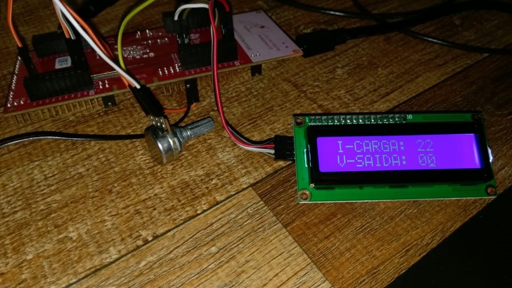
    I can sent data to slave LCD (https://www.makerlab-electronics.com/product/16x2-lcd-display-i2c-white-on-blue/).

    I can write on the LCD normally now.

    I will send here my code. because there is nothing this on the internet ( I2C - LCD with F28379D)

    Please, wait to close topic

  • this was code I used :

    // Included Files
    //
    #include "F28x_Project.h"
    # include "stdio.h"
    
    //#include "LCD.h"
    //
    // Defines **************** LCD
    //
    #define I2C_SLAVE_ADDR        0x27
    #define I2C_NUMBYTES          1
    #define I2C_EEPROM_HIGH_ADDR  0x00
    #define I2C_EEPROM_LOW_ADDR   0x30
    // Defines **************** LCD
    
    //
    // Globals ******************** LCD
    //
    struct I2CMSG I2cMsgOut1={ I2C_MSGSTAT_SEND_WITHSTOP,
                               I2C_SLAVE_ADDR,
                               I2C_NUMBYTES};
    
    
    struct I2CMSG I2cMsgIn1={ I2C_MSGSTAT_SEND_NOSTOP,
                              I2C_SLAVE_ADDR,
                              I2C_NUMBYTES};
    
    struct I2CMSG *CurrentMsgPtr;
    Uint16 PassCount;
    Uint16 FailCount;
    unsigned int decimal;
    unsigned int unidade;
    long relogio = 0;
    long relogio2 = 0;  // nao usa
    long relogio3 = 0;  // nao usa
    
    //
    // Globals ********************  LCD
    //
    
    //
    // Function Prototypes  I2C LCD
    //**********************************
    void   I2CA_Init(void);
    Uint16 I2CA_WriteData(struct I2CMSG *msg);
    void init_LCD(void);
    void I2C_out(Uint16 data);
    void LCD_command(unsigned int c);
    void LCD_write(unsigned int val);
    void convert(int c);
    void dec_unid_convert(unsigned numero);
    void intro(void);
    //void atualiza_LCD(void);
    // Function Prototypes  I2C LCD
    //**********************************
    
    // Main
    //
    void main(void)
    {
       Uint16 i;
       CurrentMsgPtr = &I2cMsgOut1;
    
    //
    // Step 1. Initialize System Control:
    // PLL, WatchDog, enable Peripheral Clocks
    // This example function is found in the F2837xD_SysCtrl.c file.
    //
       InitSysCtrl();
    
    //
    // Step 2. Initialize GPIO:
    // This example function is found in the F2837xD_Gpio.c file and
    // illustrates how to set the GPIO to it's default state.
    //
       InitGpio();
    
    //
    // For this example, only init the pins for the SCI-A port.
    // These functions are found in the F2837xD_Gpio.c file.
    //
       GPIO_SetupPinMux(104, GPIO_MUX_CPU1, 1);
       GPIO_SetupPinMux(105, GPIO_MUX_CPU1, 1);
    
    //
    // Step 3. Clear all __interrupts and initialize PIE vector table:
    // Disable CPU __interrupts
    //
       DINT;
    
    //
    // Initialize PIE control registers to their default state.
    // The default state is all PIE __interrupts disabled and flags
    // are cleared.
    // This function is found in the F2837xD_PieCtrl.c file.
    //
       InitPieCtrl();
    
    //
    // Disable CPU __interrupts and clear all CPU __interrupt flags:
    //
       IER = 0x0000;
       IFR = 0x0000;
    
    //
    // Initialize the PIE vector table with pointers to the shell Interrupt
    // Service Routines (ISR).
    // This will populate the entire table, even if the __interrupt
    // is not used in this example.  This is useful for debug purposes.
    // The shell ISR routines are found in F2837xD_DefaultIsr.c.
    // This function is found in F2837xD_PieVect.c.
    //
       InitPieVectTable();
    
    
    //
    // Step 4. Initialize the Device Peripherals:
    //
       I2CA_Init();
    
    //
    // Step 5. User specific code
    //
    
    //
    // Clear Counters
    //
       PassCount = 0;
       FailCount = 0;


    //
    // Enable CPU INT8 which is connected to PIE group 8
    //
       IER |= M_INT8;
       EINT;


       init_LCD();
       intro();
    
       int connt = 35;
    
    
       while(1){
    
       relogio ++;
    
       if(relogio > 2000000){
           relogio = 0;
           relogio2++;
    }
    
       if(relogio2 > 5){
    
          relogio2 = 0;
    
    
          LCD_command(0x8A);        // POSITION
    
          dec_unid_convert(connt);
    
    
          convert(decimal);
          convert(unidade);
    
          LCD_command(0xCA);        // POSITION
    
          dec_unid_convert(connt);
    
    
          convert(decimal);
          convert(unidade);
    
    
          connt --;
    
          if(connt < 0) connt = 35;
    
    }
    
       }
    
    }
    
    //
    // I2CA_Init - Initialize I2CA settings
    //
    void I2CA_Init(void)
    {
       I2caRegs.I2CSAR.all = 0x0027;     // Slave address - EEPROM control code
    
       I2caRegs.I2CPSC.all = 6;          // Prescaler - need 7-12 Mhz on module clk
       I2caRegs.I2CCLKL = 140;            // Prescalers set for 100kHz bit rate
       I2caRegs.I2CCLKH = 140;             //At a 100khz I2C clock
       I2caRegs.I2CIER.all = 0x00;       // DESAable SCD & ARDY __interrupts
       I2caRegs.I2CMDR.all = 0x0020;     // Take I2C out of reset
       I2caRegs.I2CFFTX.all = 0x6000;    // Enable FIFO mode and TXFIFO
       I2caRegs.I2CFFRX.all = 0x2040;    // Enable RXFIFO, clear RXFFINT,
    
       return;
    }
    
    Uint16 I2CA_WriteData(struct I2CMSG *msg)
    {
       Uint16 i;
    
       //
       // Wait until the STP bit is cleared from any previous master communication.
       // Clearing of this bit by the module is delayed until after the SCD bit is
       // set. If this bit is not checked prior to initiating a new message, the
       // I2C could get confused.
       //
       if(I2caRegs.I2CMDR.bit.STP == 1)
       {
          return I2C_STP_NOT_READY_ERROR;
       }
    
       //
       // Setup slave address
       //
       I2caRegs.I2CSAR.all = msg->SlaveAddress;
    
       //
       // Check if bus busy
       //
       if(I2caRegs.I2CSTR.bit.BB == 1)
       {
          return I2C_BUS_BUSY_ERROR;
       }
    
       //
       // Setup number of bytes to send
       // MsgBuffer + Address
       //
       I2caRegs.I2CCNT = msg->NumOfBytes+2;
    
       //
       // Setup data to send
       //
       I2caRegs.I2CDXR.all = msg->MemoryHighAddr;
       I2caRegs.I2CDXR.all = msg->MemoryLowAddr;
    
       for (i=0; i < msg->NumOfBytes; i++)
       {
          I2caRegs.I2CDXR.all = *(msg->MsgBuffer+i);
       }
    
       //
       // Send start as master transmitter
       //
       I2caRegs.I2CMDR.all = 0x6E20;
    
       return I2C_SUCCESS;
    }


    void init_LCD(void) {
    
         DELAY_US(30000);
         LCD_command(0x02);
         DELAY_US(40);
         LCD_command(0x28);
         DELAY_US(40);
         LCD_command(0x0E);
         DELAY_US(40);
         LCD_command(0x06);
         DELAY_US(1500);
         LCD_command(0x01);
    
    }
    
    void I2C_out(Uint16 data){
    
         *CurrentMsgPtr->MsgBuffer = data;  // 36  ASCII
          I2CA_WriteData(&I2cMsgOut1);
    }
    
    
    void LCD_command(unsigned int c){
    
        unsigned int commandEo;
        unsigned int commandEi;
        commandEo = 0x08;       //LED = 1, E = 0, RW = 0, RS = 0
        commandEi = 0x0C;       //LED = 1, E = 1, RW = 0, RS = 0
    
        unsigned int result = 0;
    
        result = (c&0xf0) | commandEi;I2C_out(result);
        result = (c&0xf0) | commandEi;I2C_out(result);
    
        result = (c&0xf0) | commandEo;I2C_out(result);
        result = (c&0xf0) | commandEo;I2C_out(result);
    
        result = (c&0xf0) | commandEi;I2C_out(result);
        result = (c&0xf0) | commandEi;I2C_out(result);
    
    
        DELAY_US(4000);
    
        result = (c<<4) | commandEi;  I2C_out(result);
        result = (c<<4) | commandEi;  I2C_out(result);
    
        result = (c<<4) | commandEo;  I2C_out(result);
        result = (c<<4) | commandEo;  I2C_out(result);
    
        result = (c<<4) | commandEi;  I2C_out(result);
        result = (c<<4) | commandEi;  I2C_out(result);
    
    
        DELAY_US(4000);


    }
    
    void LCD_write(unsigned int c){
    
        unsigned int commandEo;
        unsigned int commandEi;
    
         commandEo = 0x09;       //LED = 1, E = 0, RW = 0, RS = 1
         commandEi = 0x0D;       //LED = 1, E = 1, RW = 0, RS = 1
    
         unsigned int result = 0;
    
         result = (c&0xf0) | commandEi;I2C_out(result);
         result = (c&0xf0) | commandEi;I2C_out(result);
    
         result = (c&0xf0) | commandEo;I2C_out(result);
         result = (c&0xf0) | commandEo;I2C_out(result);
    
         result = (c&0xf0) | commandEi;I2C_out(result);
         result = (c&0xf0) | commandEi;I2C_out(result);
    
         DELAY_US(4000);
    
         result = (c<<4) | commandEi;  I2C_out(result);
         result = (c<<4) | commandEi;  I2C_out(result);
    
    
         result = (c<<4) | commandEo;  I2C_out(result);
         result = (c<<4) | commandEo;  I2C_out(result);
    
         result = (c<<4) | commandEi;  I2C_out(result);
         result = (c<<4) | commandEi;  I2C_out(result);
    
         DELAY_US(4000);
    
    }// end LCD
    
    void convert(int c){
        LCD_write(c+48);
    }
    
    void dec_unid_convert(unsigned int numero){
       decimal = numero/10;
       unidade = numero - (decimal*10);
    }
    
    void intro(void){
    
    
          // WRITE ON THE LCD :  I - CARGA
          LCD_write(32);
          LCD_write(73);
          LCD_write(45);
          LCD_write(67);
          LCD_write(65);LCD_write(82);LCD_write(71);LCD_write(65);LCD_write(58);LCD_write(32);LCD_write(32);LCD_write(32);LCD_write(32);LCD_write(65);
    
          LCD_command(0xC0);    // LINE 2
          // WRITE ON THE : V - SAIDA
          LCD_write(32);
          LCD_write(86);
          LCD_write(45);
          LCD_write(83);
          LCD_write(65);LCD_write(73);LCD_write(68);LCD_write(65);LCD_write(58);LCD_write(32);LCD_write(32);LCD_write(32);LCD_write(32);LCD_write(86);
    
          LCD_command(0x80);    // LINE 1
    }
    /*
    void atualiza_LCD(void){
        if(relogio > 80000){
                    relogio = 0;
    
                    LCD_command(0x8A);
    
                    dec_unid_convert(Iomed);
    
                    convert(decimal);
                    convert(unidade);
    
                    LCD_command(0xCA);
    
                    dec_unid_convert(Vomed);
    
                    convert(decimal);
                    convert(unidade);
      }
    }*/


  • Hi Tiago,

    I'm happy to hear that you were able to get this working and thank you for sharing your code/solution.

    You said that removing the High/Low address portions from the write_data function makes the communication not work? That seems odd, since the high/low address attributes of the I2C_message structure aren't defined, but maybe there's a good explanation for that (i.e. need to write bytes of zeros or something before sending data).

    Maybe looking at the waveforms would help explain this as well, if you're wanting a better understanding. Either way at least you got something working =).

    Best,

    Kevin