This thread has been locked.

If you have a related question, please click the "Ask a related question" button in the top right corner. The newly created question will be automatically linked to this question.

CCS/TMS320F28027: Can't debug because pf

Part Number: TMS320F28027

Tool/software: Code Composer Studio

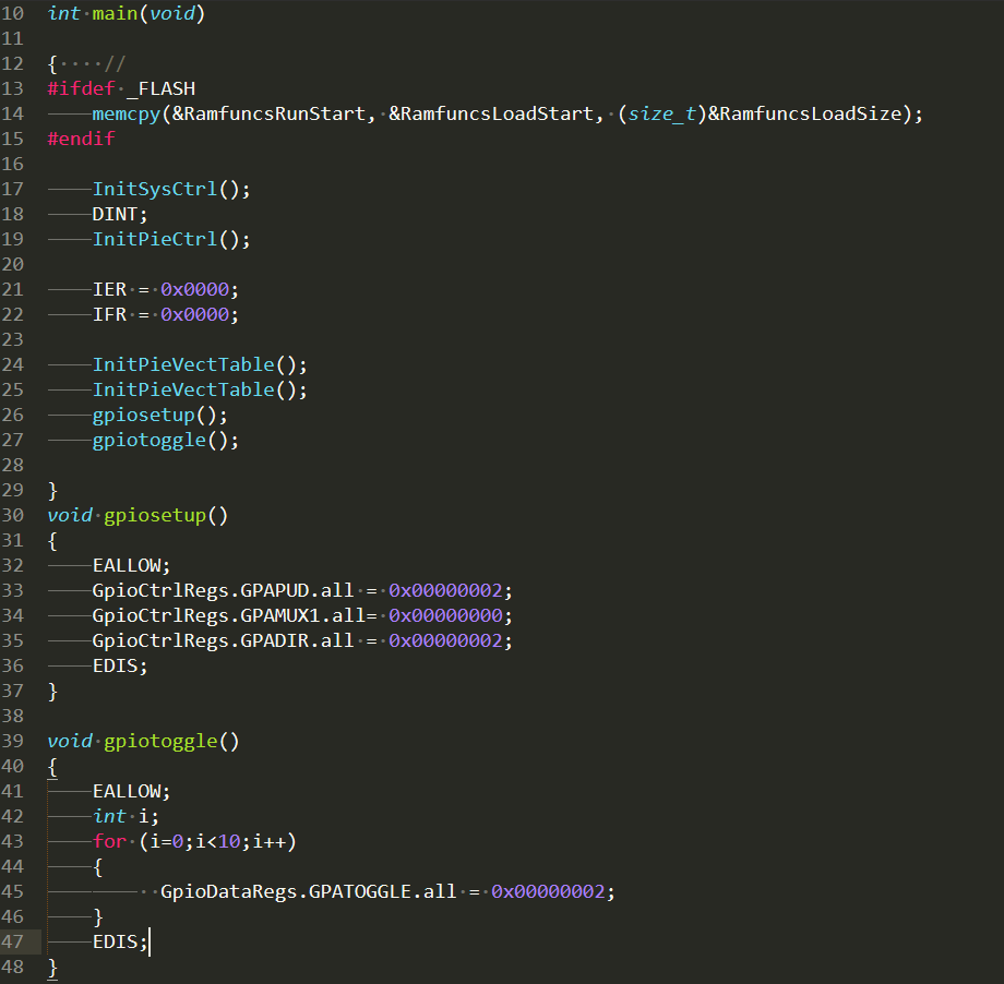
Hi guys, so I found a simple project on the internet which is supposed to toggle LED's for my C2000 launchpad running a TMS320F28027. I tried to build it, and I included all the dependecies and the build works fine. However, I get a strange error when I try to go on debug mode. 

The error says : Break at address "0x3ff5f5" with no debug information available, or outside of program code. 

When I look at this address, I find the register  ESTOP0. 

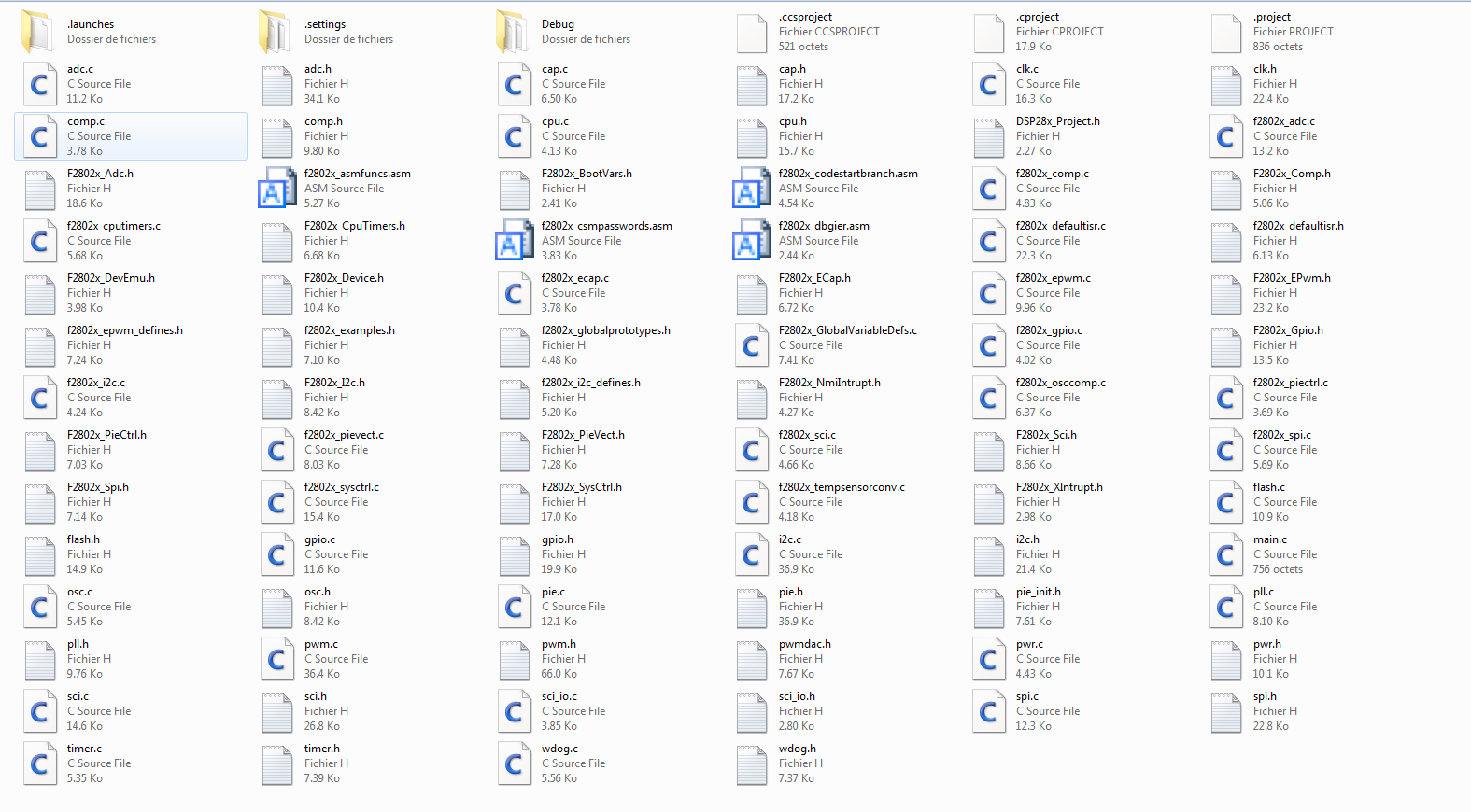
Does anyone have a clue about solving this issue ? Here is a picture of my project files and error : 

  • Can't debug because of ESTOP0 *** sorry for the mistake in the title.
  • Amine,

    The address "0x3ff5f5" is located in the boot ROM and stopped at 'wait' (ESTOP0). It looks like you did not set the boot key under the Scripts menu in CCS. Please see the following workshop:

    processors.wiki.ti.com/.../C2000_Archived_Workshops

    In the workshop manual, see page 39, step 9. In summary, you need to configure the device by loading values into EMU_KEY and EMU BMODE so the bootloader will jump to “RAMM0” at address 0x000000. Set the bootloader mode using the menu bar by clicking: Scripts, then EMU Boot Mode Select, and finally EMU_BOOT_SARAM. If the device is power cycled be sure to re-configure the boot mode to EMU_BOOT_SARAM.

    The above reference workshop uses a controlSTICK, but it can be easily modified to use the F28027 LaunchPad.

    I hope this helps. If this answers your question, please click the green "Verified Answer" button. Thanks.

    - Ken
  • Hi sir,
    There's something I do not fully understand :
    I'm new to the TMS family. I've worked with MPS's,pic and arm but first time with TMS.

    So there seem to be a command file for the linker to use to properly load the programs. I've seen them in the examples of the course you gave me. From my understanding, these command are used by the IDE to properly write the program in the flash / RAM of the MCU.

    When trying to create some examples, I did not write any command file. Could this be the reason why I had the above mistake ?

    Thank you !
  • Amine,

    The linker command file describes a system’s available memory and specifies where the code sections will be placed in memory. You can either supply a linker command file (like I did in the lab exercises) or could use the default linker command file that is supplied by CCS for the device when creating a project. Please see the Lab 1 exercise for more details.

    I hope this helps. If this answers your question, please click the green "Verified Answer" button. Thanks.

    - Ken