This thread has been locked.

If you have a related question, please click the "Ask a related question" button in the top right corner. The newly created question will be automatically linked to this question.

TMS320F28379D: Errors when trying to build the program from simulink to the board.

Part Number: TMS320F28379D
Other Parts Discussed in Thread: C2000WARE

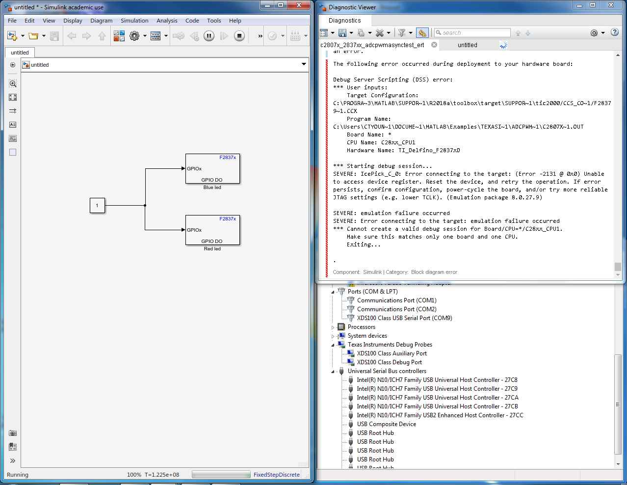
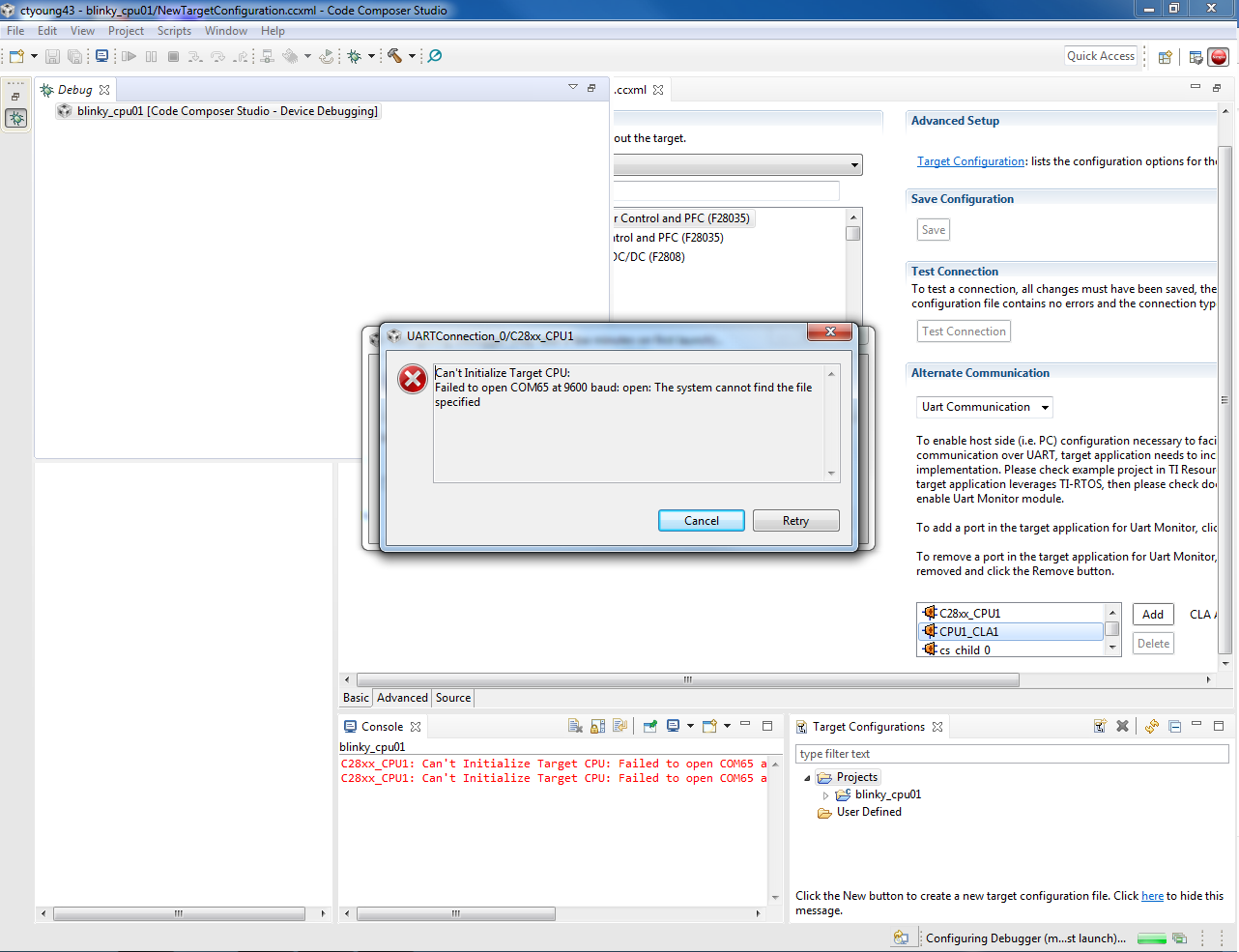
I know this might seem like a more of a MATHWORK proplem then a TI issue but I'm asking you guys because i believe there to be a connection issue to where simulink can't see the board. I was wondering how do i know that my board is connected to the computer in the right way for it to work properly. in the pic provided the device manger shows texas instruments debug probes is this connect? if not how do i fix it?

  • Smith,

    Do you have CCS installed in your machine? If so, there is a easy way to check.

    If you have only MATLAB / simulink, someone from Mathworks should be able to help you.

    Regards,
    Manoj
  • I do have it installed on the computer.

  • Hi Sam,

    I see from snap, the untitled model is running (Left snap - at the bottom shows running)?

    Make sure none of the other applications are actively connected to board including CCS.

    Try restarting MATLAB or Rebooting PC and then deploy the model where you are seeing the error.

  • trying to load an example in through ccs I'm getting this.

  • This is from a configuration test
    [Start: Texas Instruments XDS100v2 USB Debug Probe_0]

    Execute the command:

    %ccs_base%/common/uscif/dbgjtag -f %boarddatafile% -rv -o -F inform,logfile=yes -S pathlength -S integrity

    [Result]


    -----[Print the board config pathname(s)]------------------------------------

    C:\Users\CTYOUN~1\AppData\Local\TEXASI~1\
    CCS\ti\1\0\BrdDat\testBoard.dat

    -----[Print the reset-command software log-file]-----------------------------

    This utility has selected a 100- or 510-class product.
    This utility will load the adapter 'jioserdesusb.dll'.
    The library build date was 'May 30 2018'.
    The library build time was '23:03:35'.
    The library package version is '8.0.27.9'.
    The library component version is '35.35.0.0'.
    The controller does not use a programmable FPGA.
    The controller has a version number of '4' (0x00000004).
    The controller has an insertion length of '0' (0x00000000).
    This utility will attempt to reset the controller.
    This utility has successfully reset the controller.

    -----[Print the reset-command hardware log-file]-----------------------------

    The scan-path will be reset by toggling the JTAG TRST signal.
    The controller is the FTDI FT2232 with USB interface.
    The link from controller to target is direct (without cable).
    The software is configured for FTDI FT2232 features.
    The controller cannot monitor the value on the EMU[0] pin.
    The controller cannot monitor the value on the EMU[1] pin.
    The controller cannot control the timing on output pins.
    The controller cannot control the timing on input pins.
    The scan-path link-delay has been set to exactly '0' (0x0000).

    -----[The log-file for the JTAG TCLK output generated from the PLL]----------

    There is no hardware for programming the JTAG TCLK frequency.

    -----[Measure the source and frequency of the final JTAG TCLKR input]--------

    There is no hardware for measuring the JTAG TCLK frequency.

    -----[Perform the standard path-length test on the JTAG IR and DR]-----------

    This path-length test uses blocks of 64 32-bit words.

    The test for the JTAG IR instruction path-length failed.
    The JTAG IR instruction scan-path is stuck-at-ones.

    The test for the JTAG DR bypass path-length failed.
    The JTAG DR bypass scan-path is stuck-at-ones.

    -----[Perform the Integrity scan-test on the JTAG IR]------------------------

    This test will use blocks of 64 32-bit words.
    This test will be applied just once.

    Do a test using 0xFFFFFFFF.
    Scan tests: 1, skipped: 0, failed: 0
    Do a test using 0x00000000.
    Test 2 Word 0: scanned out 0x00000000 and scanned in 0xFFFFFFFF.
    Test 2 Word 1: scanned out 0x00000000 and scanned in 0xFFFFFFFF.
    Test 2 Word 2: scanned out 0x00000000 and scanned in 0xFFFFFFFF.
    Test 2 Word 3: scanned out 0x00000000 and scanned in 0xFFFFFFFF.
    Test 2 Word 4: scanned out 0x00000000 and scanned in 0xFFFFFFFF.
    Test 2 Word 5: scanned out 0x00000000 and scanned in 0xFFFFFFFF.
    Test 2 Word 6: scanned out 0x00000000 and scanned in 0xFFFFFFFF.
    Test 2 Word 7: scanned out 0x00000000 and scanned in 0xFFFFFFFF.
    The details of the first 8 errors have been provided.
    The utility will now report only the count of failed tests.
    Scan tests: 2, skipped: 0, failed: 1
    Do a test using 0xFE03E0E2.
    Scan tests: 3, skipped: 0, failed: 2
    Do a test using 0x01FC1F1D.
    Scan tests: 4, skipped: 0, failed: 3
    Do a test using 0x5533CCAA.
    Scan tests: 5, skipped: 0, failed: 4
    Do a test using 0xAACC3355.
    Scan tests: 6, skipped: 0, failed: 5
    Some of the values were corrupted - 83.3 percent.

    The JTAG IR Integrity scan-test has failed.

    -----[Perform the Integrity scan-test on the JTAG DR]------------------------

    This test will use blocks of 64 32-bit words.
    This test will be applied just once.

    Do a test using 0xFFFFFFFF.
    Scan tests: 1, skipped: 0, failed: 0
    Do a test using 0x00000000.
    Test 2 Word 0: scanned out 0x00000000 and scanned in 0xFFFFFFFF.
    Test 2 Word 1: scanned out 0x00000000 and scanned in 0xFFFFFFFF.
    Test 2 Word 2: scanned out 0x00000000 and scanned in 0xFFFFFFFF.
    Test 2 Word 3: scanned out 0x00000000 and scanned in 0xFFFFFFFF.
    Test 2 Word 4: scanned out 0x00000000 and scanned in 0xFFFFFFFF.
    Test 2 Word 5: scanned out 0x00000000 and scanned in 0xFFFFFFFF.
    Test 2 Word 6: scanned out 0x00000000 and scanned in 0xFFFFFFFF.
    Test 2 Word 7: scanned out 0x00000000 and scanned in 0xFFFFFFFF.
    The details of the first 8 errors have been provided.
    The utility will now report only the count of failed tests.
    Scan tests: 2, skipped: 0, failed: 1
    Do a test using 0xFE03E0E2.
    Scan tests: 3, skipped: 0, failed: 2
    Do a test using 0x01FC1F1D.
    Scan tests: 4, skipped: 0, failed: 3
    Do a test using 0x5533CCAA.
    Scan tests: 5, skipped: 0, failed: 4
    Do a test using 0xAACC3355.
    Scan tests: 6, skipped: 0, failed: 5
    Some of the values were corrupted - 83.3 percent.

    The JTAG DR Integrity scan-test has failed.

    [End: Texas Instruments XDS100v2 USB Debug Probe_0]
  •  This is what shows up on the device manger

  • I'm sure this is important news but using another board same type i was able to run an example and also got the simulink part working also but i would still like to figure out what the issue is with the other board though just in case the issue tries to happen with this board that is working.

  • Sam,

    Why have you chosen "Uart Communication" in Alternate communication option?

    Regards,
    Manoj
  • Not sure what you mean but I have tried it when the uart communication is blank also

  • It looks like a hardware issue. Is this the only board you have this problem?

    -Manoj
  • I'm not sure only tried one other board.
  • Sam,

    It is not CCS issue. I'm not sure what support TI can provide as it looks like a hardware issue.

    Regards,
    Manoj
  • Also is there anyway you can help me understand the pin layout of this board like if I want to use GPIO10 what pin would the correspond with?
  • It is my understand that you are working on custom board and not TI board. Am I correct?
  • No i have the tms320f28379d launchpad it’s a ti board.
  • Have you ever connected to this board? I'm wondering whether you have damaged the board (or) chip in debug process.
  • Sam,

    I tend to agree with Manoj here. Your board may be damaged, but lets try a few things to confirm it:

    Please run through the JTAG debug guide (http://www.ti.com/lit/spracf0 ).
    In addition to running through the JTAG debug guide, you should ensure that all of the voltages are at the appropriate levels. There are a few test points and header locations you can check with a voltmeter.

    For the pinout of the board, the schematic and design files are located in c2000Ware under the \boards\LaunchPads directory. Additionally please download and refer to the LaunchPad User's Guide for this board which can be found on the tool page: www.ti.com/launchxl-f28379d . The pin map and copy of the schematic are found within the document there as well.

    -Mark