Other Parts Discussed in Thread: CONTROLSUITE
Tool/software: Code Composer Studio
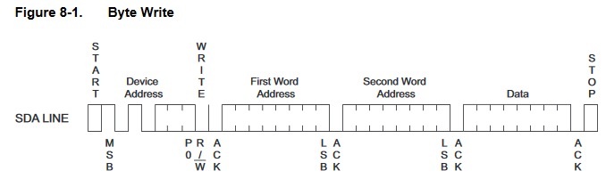
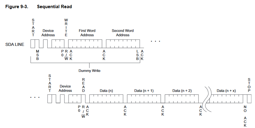
Using TMS320f28335, I am trying to write and read from EEPROM of type TM24M01.
I just modified an example in \ti\controlSUITE\device_support\f2833x\v133\DSP2833x_examples_ccsv4. Writing and reading is working well. My problem is while try to write to a next address and over write the current address. Reading from both the address is the same.
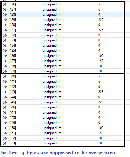
I am trying to write just to the first page of the device(256 baytes/page). what could be the reason? My modified source and screen shot of the reading is attached here with.
#include "DSP28x_Project.h" // Device Headerfile and Examples Include File
#define I2C_SLAVE_ADDR 0x50
#define I2C_NUMBYTES 14
#define I2C_EEPROM_HIGH_ADDR 0x00
#define I2C_EEPROM_LOW_ADDR 0x0F
void I2CA_Init(void);
Uint16 I2CA_WriteData(struct I2CMSG *msg);
Uint16 I2CA_ReadData(struct I2CMSG *msg);
Uint16 I2CA_WriteDataConfig(struct I2CMSG *msg);
Uint16 I2CA_ReadDataConfig(struct I2CMSG *msg);
interrupt void i2c_int1a_isr(void);
interrupt void cpu_timer0_isr(void);
Uint16 EEPROM_Buffer_Init();
Uint16 EEPROM_ParaMetersUpdate();
interrupt void cpu_timer0_isr(void);
Uint16 EEPROM_Buffer_Init();
Uint16 EEPROM_ParaMetersUpdate();
Uint16 EEPROM_DataMgt();
Uint16 I2CA_PointerOverWrite(struct I2CMSG *msg);
Uint16 Error;
Uint16 tempMsgStatus_Out,tempMsgStatus_In,tempSlaveAddress,tempNumOfBytes,
tempMemoryHighAddr,tempMemoryLowAddr;
Uint32 MemoryHighLastAddr;
Uint32 MemoryLowLastAddr;
tempMemoryHighAddr,tempMemoryLowAddr;
Uint32 MemoryHighLastAddr;
Uint32 MemoryLowLastAddr;
Uint16 PassCount, WriteCounter,L, i,k;
Uint16 Temparray[256];
#define M_Time_100ms 3
Uint16 Mtime;
Uint16 Mtime;
struct I2CMSG I2cMsgOut1;
struct I2CMSG I2cMsgIn1;
struct I2CMSG *CurrentMsgPtr;
struct I2CMSG *CurrentMsgPtr;
void main(void)
{
// Uint16 Error;
// Uint16 i;
// CurrentMsgPtr = &I2cMsgOut1;
// I2cMsgOut1.MsgBuffer[0] = 0x00;
// Step 1. Initialize System Control:
// PLL, WatchDog, enable Peripheral Clocks
// This example function is found in the DSP2833x_SysCtrl.c file.
InitSysCtrl();
// I2cMsgOut1.MsgBuffer[0] = 0x00;
// Step 1. Initialize System Control:
// PLL, WatchDog, enable Peripheral Clocks
// This example function is found in the DSP2833x_SysCtrl.c file.
InitSysCtrl();
// Step 2. Initalize GPIO:
// This example function is found in the DSP2833x_Gpio.c file and
// illustrates how to set the GPIO to it's default state.
// InitGpio();
// Setup only the GP I/O only for I2C functionality
InitI2CGpio();
// Step 3. Clear all interrupts and initialize PIE vector table:
// Disable CPU interrupts
DINT;
// Disable CPU interrupts
DINT;
// Initialize PIE control registers to their default state.
// The default state is all PIE interrupts disabled and flags
// are cleared.
// This function is found in the DSP2833x_PieCtrl.c file.
InitPieCtrl();
// The default state is all PIE interrupts disabled and flags
// are cleared.
// This function is found in the DSP2833x_PieCtrl.c file.
InitPieCtrl();
// Disable CPU interrupts and clear all CPU interrupt flags:
IER = 0x0000;
IFR = 0x0000;
IER = 0x0000;
IFR = 0x0000;
// Initialize the PIE vector table with pointers to the shell Interrupt
// Service Routines (ISR).
// This will populate the entire table, even if the interrupt
// is not used in this example. This is useful for debug purposes.
// The shell ISR routines are found in DSP2833x_DefaultIsr.c.
// This function is found in DSP2833x_PieVect.c.
InitPieVectTable();
// Service Routines (ISR).
// This will populate the entire table, even if the interrupt
// is not used in this example. This is useful for debug purposes.
// The shell ISR routines are found in DSP2833x_DefaultIsr.c.
// This function is found in DSP2833x_PieVect.c.
InitPieVectTable();
// Interrupts that are used in this example are re-mapped to
// ISR functions found within this file.
EALLOW; // This is needed to write to EALLOW protected registers
PieVectTable.I2CINT1A = &i2c_int1a_isr;
PieVectTable.TINT0 = &cpu_timer0_isr;
EDIS; // This is needed to disable write to EALLOW protected registers
// ISR functions found within this file.
EALLOW; // This is needed to write to EALLOW protected registers
PieVectTable.I2CINT1A = &i2c_int1a_isr;
PieVectTable.TINT0 = &cpu_timer0_isr;
EDIS; // This is needed to disable write to EALLOW protected registers
// Step 4. Initialize all the Device Peripherals:
// This function is found in DSP2833x_InitPeripherals.c
// InitPeripherals(); // Not required for this example
// This function is found in DSP2833x_InitPeripherals.c
// InitPeripherals(); // Not required for this example
I2CA_Init();
InitCpuTimers();
ConfigCpuTimer(&CpuTimer0, 100, 1000);
InitCpuTimers();
ConfigCpuTimer(&CpuTimer0, 100, 1000);
PieCtrlRegs.PIEIER8.bit.INTx1 = 1;
PieCtrlRegs.PIEIER1.bit.INTx7 = 1; // timer 0 config
PieCtrlRegs.PIEIER1.bit.INTx7 = 1; // timer 0 config
IER |= M_INT8|M_INT1;
StartCpuTimer0();
StartCpuTimer0();
EINT;
EEPROM_Buffer_Init();
for(;;)
{
//////////////////////////////////
// EEPROM_DataMgt();
{
//////////////////////////////////
// EEPROM_DataMgt();
} // end of for(;;)
} // end of main
interrupt void cpu_timer0_isr(void)
{
Mtime++;
if (Mtime >= M_Time_100ms)
{
Mtime = 0;
EEPROM_DataMgt();
{
Mtime = 0;
EEPROM_DataMgt();
}
PieCtrlRegs.PIEACK.all |= PIEACK_GROUP1;
}
void I2CA_Init(void)
{
// Initialize I2C
I2caRegs.I2CSAR = 0x0050; // Slave address - EEPROM control code
#if (CPU_FRQ_150MHZ) // Default - For 150MHz SYSCLKOUT
I2caRegs.I2CPSC.all = 14; // Prescaler - need 7-12 Mhz on module clk (150/15 = 10MHz)
#endif
#if (CPU_FRQ_100MHZ) // For 100 MHz SYSCLKOUT
I2caRegs.I2CPSC.all = 9; // Prescaler - need 7-12 Mhz on module clk (100/10 = 10MHz)
#endif
I2caRegs.I2CPSC.all = 14; // Prescaler - need 7-12 Mhz on module clk (150/15 = 10MHz)
#endif
#if (CPU_FRQ_100MHZ) // For 100 MHz SYSCLKOUT
I2caRegs.I2CPSC.all = 9; // Prescaler - need 7-12 Mhz on module clk (100/10 = 10MHz)
#endif
I2caRegs.I2CCLKL = 10; // NOTE: must be non zero
I2caRegs.I2CCLKH = 5; // NOTE: must be non zero
I2caRegs.I2CIER.all = 0x24; // Enable SCD & ARDY interrupts
I2caRegs.I2CCLKH = 5; // NOTE: must be non zero
I2caRegs.I2CIER.all = 0x24; // Enable SCD & ARDY interrupts
I2caRegs.I2CMDR.all = 0x0020; // Take I2C out of reset
// Stop I2C when suspended
// Stop I2C when suspended
I2caRegs.I2CFFTX.all = 0x6000; // Enable FIFO mode and TXFIFO
I2caRegs.I2CFFRX.all = 0x2040; // Enable RXFIFO, clear RXFFINT,
I2caRegs.I2CFFRX.all = 0x2040; // Enable RXFIFO, clear RXFFINT,
return;
}
}
Uint16 EEPROM_Buffer_Init()
{
PassCount = 0;
WriteCounter = 0;
L= 0;
k =0;
PassCount = 0;
WriteCounter = 0;
L= 0;
k =0;
// Clear incoming message buffer
for (i = 0; i < I2C_MAX_BUFFER_SIZE; i++)
{
I2cMsgIn1.MsgBuffer[i] = 0x0000;
I2cMsgOut1.MsgBuffer[i] = 0x0000;
}
tempMsgStatus_Out = I2C_MSGSTAT_SEND_WITHSTOP;
tempMsgStatus_In = I2C_MSGSTAT_SEND_NOSTOP;
tempSlaveAddress = I2C_SLAVE_ADDR;
tempNumOfBytes = I2C_NUMBYTES ;
tempMemoryHighAddr = I2C_EEPROM_HIGH_ADDR;
tempMemoryLowAddr = I2C_EEPROM_LOW_ADDR;
I2CA_ReadDataConfig(&I2cMsgIn1);
I2CA_WriteDataConfig(&I2cMsgOut1);
return 0;
}
Uint16 EEPROM_DataMgt()
{
if( L<30) // it is to write 30times: 15 writings and 15 over writings : L is incremented after each successful writing
{
{
if(I2cMsgOut1.MsgStatus == I2C_MSGSTAT_SEND_WITHSTOP)
{
{
if( WriteCounter ==0) // writing to the next address
{
MemoryHighLastAddr = tempMemoryHighAddr; // store the current address
MemoryLowLastAddr = tempMemoryLowAddr;
{
MemoryHighLastAddr = tempMemoryHighAddr; // store the current address
MemoryLowLastAddr = tempMemoryLowAddr;
tempMemoryHighAddr = tempMemoryHighAddr;
tempMemoryLowAddr = (tempMemoryLowAddr += 0x10); // compute the next lower address to write to
I2CA_WriteDataConfig(&I2cMsgOut1); // send address and data to write
tempMemoryLowAddr = (tempMemoryLowAddr += 0x10); // compute the next lower address to write to
I2CA_WriteDataConfig(&I2cMsgOut1); // send address and data to write
}
else if( WriteCounter ==1) // over writing the current address
{
else if( WriteCounter ==1) // over writing the current address
{
tempMemoryHighAddr = MemoryHighLastAddr ; // reset to the stored address
tempMemoryLowAddr = MemoryLowLastAddr ;
I2CA_PointerOverWrite(&I2cMsgOut1);
tempMemoryLowAddr = MemoryLowLastAddr ;
I2CA_PointerOverWrite(&I2cMsgOut1);
}
else {/*I2CA_WriteDataConfig(&I2cMsgOut1); */}
else {/*I2CA_WriteDataConfig(&I2cMsgOut1); */}
Error = I2CA_WriteData(&I2cMsgOut1);
if (Error == I2C_SUCCESS)
{
L++;
WriteCounter++;
CurrentMsgPtr = &I2cMsgOut1;
I2cMsgOut1.MsgStatus = I2C_MSGSTAT_WRITE_BUSY;
{
L++;
WriteCounter++;
CurrentMsgPtr = &I2cMsgOut1;
I2cMsgOut1.MsgStatus = I2C_MSGSTAT_WRITE_BUSY;
if( WriteCounter==2)
{
WriteCounter = 0; // reset after writing the next address and overwriting the current address
{
WriteCounter = 0; // reset after writing the next address and overwriting the current address
tempMemoryHighAddr = tempMemoryHighAddr;
tempMemoryLowAddr = (tempMemoryLowAddr += 0x10); // store the written address
tempMemoryLowAddr = (tempMemoryLowAddr += 0x10); // store the written address
}
}
}
} // end of write section
} // end of write section
else // if L>32 : after finishing the writing, start reading.
{
// Check incoming message status.
if(I2cMsgIn1.MsgStatus == I2C_MSGSTAT_SEND_NOSTOP) // I2cMsgIn1.MsgStatus is initialized to I2C_MSGSTAT_SEND_NOSTOP when the program starts
{
// EEPROM address setup portion
// I2CA_ReadDataConfig(&I2cMsgIn1);
{
// Check incoming message status.
if(I2cMsgIn1.MsgStatus == I2C_MSGSTAT_SEND_NOSTOP) // I2cMsgIn1.MsgStatus is initialized to I2C_MSGSTAT_SEND_NOSTOP when the program starts
{
// EEPROM address setup portion
// I2CA_ReadDataConfig(&I2cMsgIn1);
while(I2CA_ReadData(&I2cMsgIn1) != I2C_SUCCESS)
{
// Maybe setup an attempt counter to break an infinite while
// loop. The EEPROM will send back a NACK while it is performing
// a write operation. Even though the write communique is
// complete at this point, the EEPROM could still be busy
// programming the data. Therefore, multiple attempts are
// necessary.
}
// Update current message pointer and message status
CurrentMsgPtr = &I2cMsgIn1;
I2cMsgIn1.MsgStatus = I2C_MSGSTAT_SEND_NOSTOP_BUSY;
}
// Once message has progressed past setting up the internal address
// of the EEPROM, send a restart to read the data bytes from the
// EEPROM. Complete the communication with a stop bit. MsgStatus is
// updated in the interrupt service routine.
else if(I2cMsgIn1.MsgStatus == I2C_MSGSTAT_RESTART)
{
// Read data portion
while(I2CA_ReadData(&I2cMsgIn1) != I2C_SUCCESS)
{
// Maybe setup an attempt counter to break an infinite while
// loop.
}
// Update current message pointer and message status
CurrentMsgPtr = &I2cMsgIn1;
I2cMsgIn1.MsgStatus = I2C_MSGSTAT_READ_BUSY;
}
} // end of read section
return 0;
}
Uint16 I2CA_WriteDataConfig(struct I2CMSG *msg)
{
msg->MsgStatus = tempMsgStatus_Out ;
msg->SlaveAddress = tempSlaveAddress ;
msg->NumOfBytes = tempNumOfBytes;
msg->MemoryHighAddr = tempMemoryHighAddr;
msg->MemoryLowAddr = tempMemoryLowAddr ;
msg->MsgBuffer[0] = 0x05;
msg->MsgBuffer[1] = 0x06;
msg->MsgBuffer[2] = 0x00;
msg->MsgBuffer[3] = 0xE1;
msg->MsgBuffer[4] = 0x00;
msg->MsgBuffer[5] = 0xE1;
msg->MsgBuffer[6] = 0x00;
msg->MsgBuffer[7] = 0x00;
msg->MsgBuffer[8] = 0x00 ;
msg->MsgBuffer[9] = 0x00;
msg->MsgBuffer[10] = 0x64;
msg->MsgBuffer[11] = 0x96;
msg->MsgBuffer[12] = 0x64 ;
msg->MsgBuffer[13] = 0x0A;
msg->MsgBuffer[14] = 0x00;
msg->MsgBuffer[15] = 0x00;
return 0;
}
}
Uint16 I2CA_PointerOverWrite(struct I2CMSG *msg)
{
msg->MsgStatus = tempMsgStatus_Out ;
msg->SlaveAddress = tempSlaveAddress ;
msg->NumOfBytes = tempNumOfBytes;
msg->MemoryHighAddr = tempMemoryHighAddr;
msg->MemoryLowAddr = tempMemoryLowAddr ;
msg->MsgBuffer[0] = 0x00;
msg->MsgBuffer[1] = 0x06;
msg->MsgBuffer[2] = 0x01;
msg->MsgBuffer[3] = 0xF4;
msg->MsgBuffer[4] = 0x01;
msg->MsgBuffer[5] = 0xF4;
msg->MsgBuffer[6] = 0x00;
msg->MsgBuffer[7] = 0x00;
msg->MsgBuffer[8] = 0x00 ;
msg->MsgBuffer[9] = 0x00;
msg->MsgBuffer[10] = 0x64;
msg->MsgBuffer[11] = 0x96;
msg->MsgBuffer[12] = 0x64 ;
msg->MsgBuffer[13] = 0x00;
msg->MsgBuffer[14] = 0x00 ;
msg->MsgBuffer[15] = 0x00;
return 0;
}
Uint16 I2CA_ReadDataConfig(struct I2CMSG *msg)
{
msg->MsgStatus = tempMsgStatus_In ;
msg->SlaveAddress = tempSlaveAddress ;
msg->NumOfBytes = tempNumOfBytes;
msg->MemoryHighAddr = tempMemoryHighAddr;
msg->MemoryLowAddr = tempMemoryLowAddr ;
return 0;
}
msg->SlaveAddress = tempSlaveAddress ;
msg->NumOfBytes = tempNumOfBytes;
msg->MemoryHighAddr = tempMemoryHighAddr;
msg->MemoryLowAddr = tempMemoryLowAddr ;
return 0;
}
Uint16 I2CA_WriteData(struct I2CMSG *msg)
{
Uint16 i;
{
Uint16 i;
// Wait until the STP bit is cleared from any previous master communication.
// Clearing of this bit by the module is delayed until after the SCD bit is
// set. If this bit is not checked prior to initiating a new message, the
// I2C could get confused.
if (I2caRegs.I2CMDR.bit.STP == 1)
{
return I2C_STP_NOT_READY_ERROR;
}
// Clearing of this bit by the module is delayed until after the SCD bit is
// set. If this bit is not checked prior to initiating a new message, the
// I2C could get confused.
if (I2caRegs.I2CMDR.bit.STP == 1)
{
return I2C_STP_NOT_READY_ERROR;
}
// Setup slave address
I2caRegs.I2CSAR = msg->SlaveAddress;
I2caRegs.I2CSAR = msg->SlaveAddress;
// Check if bus busy
if (I2caRegs.I2CSTR.bit.BB == 1)
{
return I2C_BUS_BUSY_ERROR;
}
if (I2caRegs.I2CSTR.bit.BB == 1)
{
return I2C_BUS_BUSY_ERROR;
}
// Setup number of bytes to send
// MsgBuffer + Address
I2caRegs.I2CCNT = msg->NumOfBytes+2;
// Setup data to send
I2caRegs.I2CDXR = msg->MemoryHighAddr;
I2caRegs.I2CDXR = msg->MemoryLowAddr;
// for (i=0; i<msg->NumOfBytes-2; i++)
for (i=0; i<msg->NumOfBytes; i++)
// MsgBuffer + Address
I2caRegs.I2CCNT = msg->NumOfBytes+2;
// Setup data to send
I2caRegs.I2CDXR = msg->MemoryHighAddr;
I2caRegs.I2CDXR = msg->MemoryLowAddr;
// for (i=0; i<msg->NumOfBytes-2; i++)
for (i=0; i<msg->NumOfBytes; i++)
{
I2caRegs.I2CDXR = *(msg->MsgBuffer+i);
}
I2caRegs.I2CDXR = *(msg->MsgBuffer+i);
}
// Send start as master transmitter
I2caRegs.I2CMDR.all = 0x6E20;
I2caRegs.I2CMDR.all = 0x6E20;
return I2C_SUCCESS;
}
Uint16 I2CA_ReadData(struct I2CMSG *msg)
{
// Wait until the STP bit is cleared from any previous master communication.
// Clearing of this bit by the module is delayed until after the SCD bit is
// set. If this bit is not checked prior to initiating a new message, the
// I2C could get confused.
if (I2caRegs.I2CMDR.bit.STP == 1)
{
return I2C_STP_NOT_READY_ERROR;
}
I2caRegs.I2CSAR = msg->SlaveAddress;
if(msg->MsgStatus == I2C_MSGSTAT_SEND_NOSTOP)
{
// Check if bus busy
if (I2caRegs.I2CSTR.bit.BB == 1)
{
return I2C_BUS_BUSY_ERROR;
}
I2caRegs.I2CCNT = 2;
I2caRegs.I2CDXR = msg->MemoryHighAddr;
I2caRegs.I2CDXR = msg->MemoryLowAddr;
I2caRegs.I2CMDR.all = 0x2620; // Send data to setup EEPROM address
}
else if(msg->MsgStatus == I2C_MSGSTAT_RESTART)
{
I2caRegs.I2CCNT = msg->NumOfBytes; // Setup how many bytes to expect
I2caRegs.I2CMDR.all = 0x2C20; // Send restart as master receiver
}
{
// Check if bus busy
if (I2caRegs.I2CSTR.bit.BB == 1)
{
return I2C_BUS_BUSY_ERROR;
}
I2caRegs.I2CCNT = 2;
I2caRegs.I2CDXR = msg->MemoryHighAddr;
I2caRegs.I2CDXR = msg->MemoryLowAddr;
I2caRegs.I2CMDR.all = 0x2620; // Send data to setup EEPROM address
}
else if(msg->MsgStatus == I2C_MSGSTAT_RESTART)
{
I2caRegs.I2CCNT = msg->NumOfBytes; // Setup how many bytes to expect
I2caRegs.I2CMDR.all = 0x2C20; // Send restart as master receiver
}
return I2C_SUCCESS;
}
}
interrupt void i2c_int1a_isr(void) // I2C-A
{
Uint16 IntSource, i;
{
Uint16 IntSource, i;
// Read interrupt source
IntSource = I2caRegs.I2CISRC.all;
// Interrupt source = stop condition detected
if(IntSource == I2C_SCD_ISRC)
{
IntSource = I2caRegs.I2CISRC.all;
// Interrupt source = stop condition detected
if(IntSource == I2C_SCD_ISRC)
{
// If completed message was writing data, reset msg to inactive state
if (CurrentMsgPtr->MsgStatus == I2C_MSGSTAT_WRITE_BUSY)
{
if (CurrentMsgPtr->MsgStatus == I2C_MSGSTAT_WRITE_BUSY)
{
CurrentMsgPtr->MsgStatus = I2C_MSGSTAT_SEND_WITHSTOP;
}
else
{
// If a message receives a NACK during the address setup portion of the
// EEPROM read, the code further below included in the register access ready
// interrupt source code will generate a stop condition. After the stop
// condition is received (here), set the message status to try again.
// User may want to limit the number of retries before generating an error.
if(CurrentMsgPtr->MsgStatus == I2C_MSGSTAT_SEND_NOSTOP_BUSY)
{
CurrentMsgPtr->MsgStatus = I2C_MSGSTAT_SEND_NOSTOP;
// PassCount++;
}
// If completed message was reading EEPROM data, reset msg to inactive state
// and read data from FIFO.
else if (CurrentMsgPtr->MsgStatus == I2C_MSGSTAT_READ_BUSY)
{
for(i=0; i < I2C_NUMBYTES; i++)
{
I2cMsgIn1.MsgBuffer[i] = I2caRegs.I2CDRR;
}
if( PassCount< 15) // stop writing the data to Temparray after 15 readings.
{
tempMemoryHighAddr = tempMemoryHighAddr ;
tempMemoryLowAddr = ((tempMemoryLowAddr += 0x10)) ;
for(k = 0; k< CurrentMsgPtr->NumOfBytes; k++)
Temparray[(14*PassCount) + k] = CurrentMsgPtr->MsgBuffer[k] ;
PassCount++;
I2CA_ReadDataConfig(&I2cMsgIn1);
}
Temparray[(14*PassCount) + k] = CurrentMsgPtr->MsgBuffer[k] ;
PassCount++;
I2CA_ReadDataConfig(&I2cMsgIn1);
}
}
else {}
}
} // end of stop condition detected
// Interrupt source = Register Access Ready
// This interrupt is used to determine when the EEPROM address setup portion of the
// read data communication is complete. Since no stop bit is commanded, this flag
// tells us when the message has been sent instead of the SCD flag. If a NACK is
// received, clear the NACK bit and command a stop. Otherwise, move on to the read
// data portion of the communication.
else if(IntSource == I2C_ARDY_ISRC)
{
if(I2caRegs.I2CSTR.bit.NACK == 1)
{
I2caRegs.I2CMDR.bit.STP = 1;
I2caRegs.I2CSTR.all = I2C_CLR_NACK_BIT;
}
else if(CurrentMsgPtr->MsgStatus == I2C_MSGSTAT_SEND_NOSTOP_BUSY)
{
CurrentMsgPtr->MsgStatus = I2C_MSGSTAT_RESTART;
else if(CurrentMsgPtr->MsgStatus == I2C_MSGSTAT_SEND_NOSTOP_BUSY)
{
CurrentMsgPtr->MsgStatus = I2C_MSGSTAT_RESTART;
}
} // end of register access ready
} // end of register access ready
else
{
// Generate some error due to invalid interrupt source
asm(" ESTOP0");
}
{
// Generate some error due to invalid interrupt source
asm(" ESTOP0");
}
// Enable future I2C (PIE Group 8) interrupts
PieCtrlRegs.PIEACK.all = PIEACK_GROUP8;
}
PieCtrlRegs.PIEACK.all = PIEACK_GROUP8;
}
//===========================================================================
// No more.
//===========================================================================
// No more.
//===========================================================================