This thread has been locked.

If you have a related question, please click the "Ask a related question" button in the top right corner. The newly created question will be automatically linked to this question.

TMS320F28379D: USB failed to be recognized

Part Number: TMS320F28379D

Dear Team,

This is another question about the USB configuration in USB bootloader.

We have a customized USB bootloader, and we have two modes to execute the bootloader.

1)  Execute the bootloader after the reset and than jump into the app code. 

2)  During the app code, receive a command through USB. And than jump into the bootloader and jump back into app after the update.

The problem is:

1) If we execute the bootloader after power up, everything goes well.

2) If we execute the bootloader by jumping from the app code. The USB cannot be recognized sometimes.

We cannot identify a certain condition when the failure happens. However, we have noticed the following wired things:

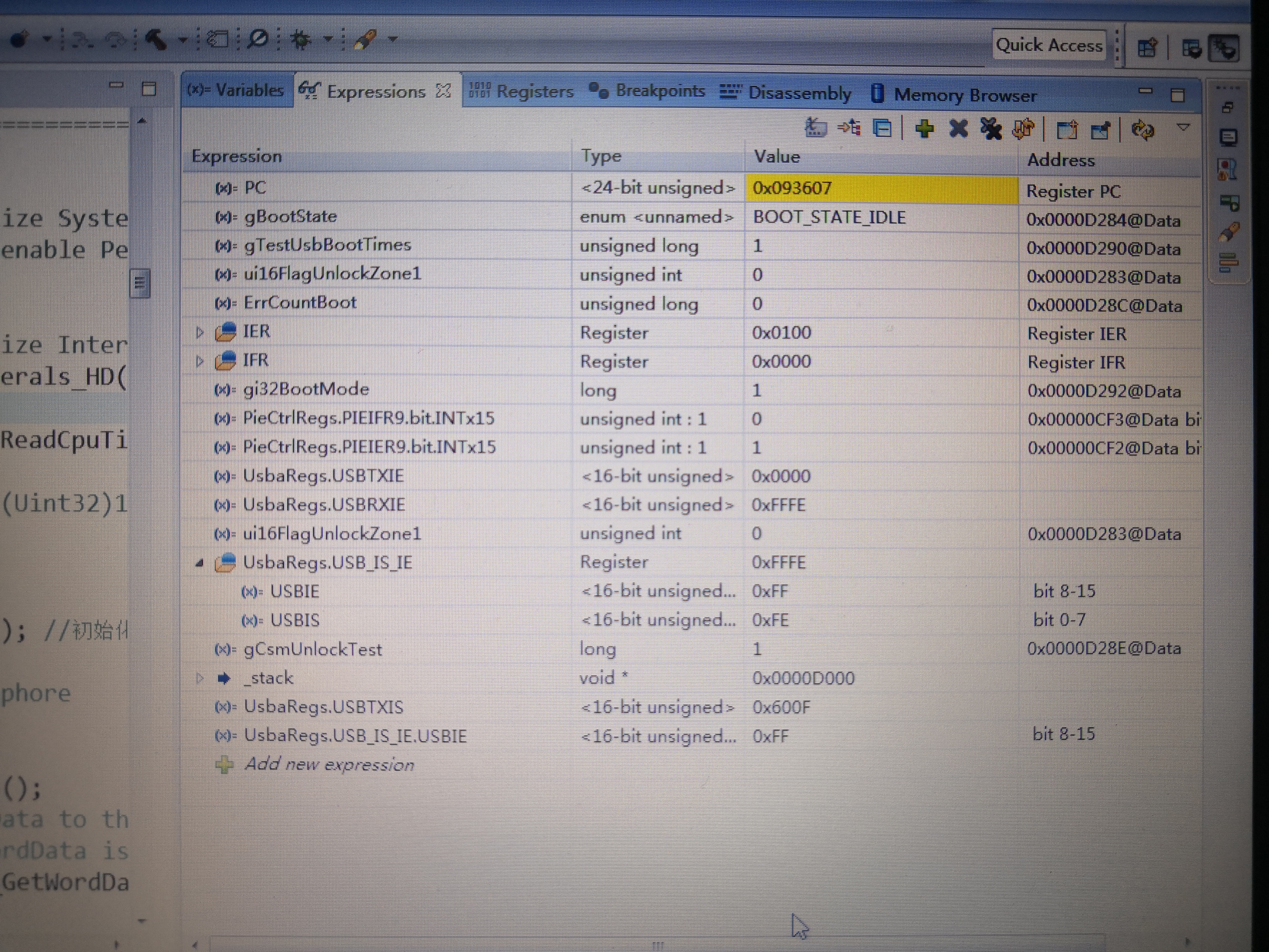
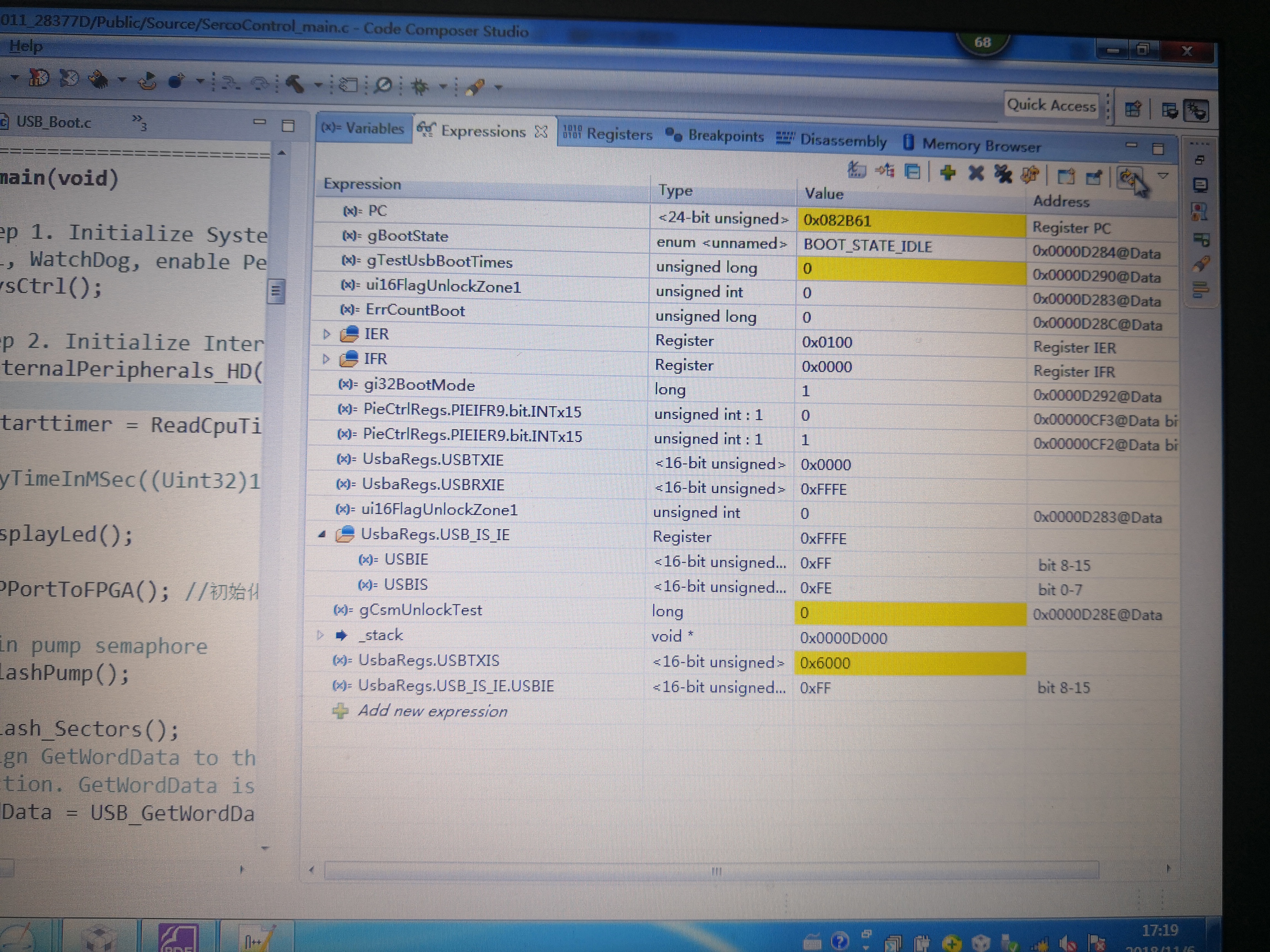
As you can see, we write 0x0003 and 0x0002 to USBTXIE and USBRXIE. However, if we execute a single step, the value of USBTXIE becomes 0x0000.

If the code is executed coutinously, USBRXIE is 0xFFFE, while USBTxIE is0x0000.

And I noticed the same question in this post:

https://e2e.ti.com/support/microcontrollers/c2000/f/171/t/722052?tisearch=e2e-sitesearch&keymatch=txie

Do you have any idea of how to config a realiable USB connection?

  • Hi Brian,

    It is hard for me to say what is causing this. Can you begin to narrow down when this occurs? I suggest setting some breakpoints to narrow down the LOC which is writing to TXIE and RXIE to give it these values. Continue to narrow it down to get to the specific lines of code, and then I can help some.

    Regards,
    sal
  • Hi Sal,

    We should have identify the problem with more detail, however, we have no idea how could this happen.

    So far, we noticed the following two weird things:

    1) The result read from USBRXIE and USBTXIE is not the value we wrote (mentioned above).

    2) The wrong PC state:

    As you can see in the .c file and disassembly window, after the BootLoadCsmUnlock() the next gCsmUnlockTest++ should be execute. However, sometimes, the PC will jump back to BootLoadCsmUnlock() and execute it again. Since no USB communication is received, the program is stucked in the function. Do you have any idea how could this happen?

    3) If we jump into bootloader from app, the USB cannot be recognized even if we re-plug the USB cable.

    The code of BootLoadCsmUnlock is attached:

    #pragma CODE_SECTION(BootLoadStart,"ramfuncs");
    
    Uint16 BootLoadCsmUnlock()
    {
    	Uint16 ui16I;
    	Uint16 ui16Sum;
    	Uint16 ui16TxBuffer[5];
    	
    	Uint16 ui16Key[8] = {0xFFFF};
        Uint16 ulFlagUnlock;
    
        for(ui16I = 0; ui16I <= 11; ui16I++)
        {
        	u16UsbRxBuffer[ui16I] = (*GetWordData)();
        }
    
    	ui16Sum = 0;
        for(ui16I=1; ui16I<=10; ui16I++)
        {
        	ui16Sum += (u16UsbRxBuffer[ui16I]>>8)&0xFF;
        	ui16Sum += (u16UsbRxBuffer[ui16I]>>0)&0xFF;
        }
    
    	if ((u16UsbRxBuffer[0] != 0xA5AA) || (u16UsbRxBuffer[1] != 0x5700)
    		|| ((u16UsbRxBuffer[2]>>8)>4) || (0xA1 != (u16UsbRxBuffer[2]&0xFF))
    		||  (0x5A != (u16UsbRxBuffer[11]&0xFF))
    		|| ((ui16Sum&0xFF) != ((u16UsbRxBuffer[11]>>8)&0xFF)))
    	{
    		ui16TxBuffer[0] = 0xA5;
    		ui16TxBuffer[1] = 0x00;
    		
    		ui16TxBuffer[2] = 0xA2;
    		ui16TxBuffer[3] = 0x5A;
    		
    		ui16TxBuffer[4] = 0xA2;
    
    		TxDataEp1(ui16TxBuffer, 5, USB_END_DATA);
    		return 0;
    	}
    
    	if ((u16UsbRxBuffer[2]>>8)&0x1) // zone(bit9):method(bit8)
    	{
    	   ui16Key[0] = 0x3139;
    	   ui16Key[1] = 0x3032;
    	   ui16Key[2] = 0x3038;
    	   ui16Key[3] = 0x3230;
    	   ui16Key[4] = 0x3033;
    	   ui16Key[5] = 0x3037;
    	   ui16Key[6] = 0x3037;
    	   ui16Key[7] = 0x3230;
    	}
    	else // Record Csm Passwords
    	{
    	   ui16Key[0] = u16UsbRxBuffer[3];
    	   ui16Key[1] = u16UsbRxBuffer[4];
    	   ui16Key[2] = u16UsbRxBuffer[5];
    	   ui16Key[3] = u16UsbRxBuffer[6];
    	   ui16Key[4] = u16UsbRxBuffer[7];
    	   ui16Key[5] = u16UsbRxBuffer[8];
    	   ui16Key[6] = u16UsbRxBuffer[9];
    	   ui16Key[7] = u16UsbRxBuffer[10];
    	}
    	ulFlagUnlock = ((u16UsbRxBuffer[2]>>9)&0x1) ?
    					CsmUnlockZone2(ui16Key):CsmUnlockZone1(ui16Key);
    /*	
    	if ((u16UsbRxBuffer[2]>>9)&0x1) // zone(bit9)
    		ulFlagUnlock = CsmUnlockZone2(&ui16Key);
    	else
    		ulFlagUnlock = CsmUnlockZone1(&ui16Key);*/
    	
    	if (1 == ulFlagUnlock)
    	{
    		ui16TxBuffer[0] = 0xA5;
    		ui16TxBuffer[1] = 0x00;
    		ui16TxBuffer[2] = 0xA1;
    		ui16TxBuffer[3] = 0x5A;
    		ui16TxBuffer[4] = 0xA1;
    
    		TxDataEp1(ui16TxBuffer, 5, USB_END_DATA);
    		return 1;
    	}
    	else
    	{
    		ui16TxBuffer[0] = 0xA5;
    		ui16TxBuffer[1] = 0x00;
    		ui16TxBuffer[2] = 0xA2;
    		ui16TxBuffer[3] = 0x5A;
    		ui16TxBuffer[4] = 0xA2;
    
    		TxDataEp1(ui16TxBuffer, 5, USB_END_DATA);
    		return 0;
    	}
    	
    }
    
    #define STATUS_FAIL          0
    #define STATUS_SUCCESS       1
    
    Uint16 CsmUnlockZone1(Uint16 ui16CsmKey[])
    {
        volatile Uint16 temp;
    	//CSM register file
    	volatile long int *CSM = (volatile long int *)0x5F000; 
    	//CSM Password location (assumingdefault Zone sel block)
    	volatile long int *CSMPWL = (volatile long int *)0x78028;
    	// If the password locations (CSMPWL) are all = ones (0xFFFF),
    	// then the zone will now be unsecure. If the password
    	// is not all ones (0xFFFF), then the code below is required
    	// to unsecure the CSM.
    	// Write the 128-bit password to the CSMKEY registers
    	// If this password matches that stored in the
    	// CSLPWL then the CSM will become unsecure. If it does not
    	// match, then the zone will remain secure.
    	// An example password of:
    	// 0x11112222333344445555666677778888 is used.
    	// *CSM++ = 0x22221111; // Register Z1_CSMKEY0 at 0x5F010
    	// *CSM++ = 0x44443333; // Register Z1_CSMKEY1 at 0x5F012
    	// *CSM++ = 0x66665555; // Register Z1_CSMKEY2 at 0x5F014
    	// *CSM++ = 0x88887777; // Register Z1_CSMKEY3 at 0x5F016
    	
        // Load the key registers with the current password. The 0xFFFF's are dummy
        // passwords.  User should replace them with the correct password for the DSP.
    
    	// If the password locations (CSMPWL) are all = ones,the zone is unsecured.
    	if (!(DcsmZ1Regs.Z1_CR.bit.ALLONE)) // Unlock when zone is secured.
    	{
    		EALLOW;
    		DcsmZ1Regs.Z1_CSMKEY0 = ui16CsmKey[0]+ui16CsmKey[1]<<16;
    		DcsmZ1Regs.Z1_CSMKEY1 = ui16CsmKey[2]+ui16CsmKey[3]<<16;
    		DcsmZ1Regs.Z1_CSMKEY2 = ui16CsmKey[4]+ui16CsmKey[5]<<16;
    		DcsmZ1Regs.Z1_CSMKEY3 = ui16CsmKey[6]+ui16CsmKey[7]<<16;
    		EDIS;	
    	}
    	else
    		return STATUS_SUCCESS;
    	
    	// If the CSM unlocked, return success, otherwise return
    	// failure.
    	if (DcsmZ1Regs.Z1_CR.bit.UNSECURE) return STATUS_SUCCESS;
    	else return STATUS_FAIL;
    		
    }
    
    Uint16 CsmUnlockZone2(Uint16 ui16CsmKey[])
    {
        volatile Uint16 temp;
    	// CSM register file
    	// volatile long int *CSM = (volatile long int *)0x5F000; 
    	// CSM Password location (assumingdefault Zone sel block)
    	// volatile long int *CSMPWL = (volatile long int *)0x78028;
    	
    	// If the password locations (CSMPWL) are all = ones (0xFFFF),
    	// then the zone will now be unsecure. If the password
    	// is not all ones (0xFFFF), then the code below is required
    	// to unsecure the CSM.
    	// Write the 128-bit password to the CSMKEY registers
    	// If this password matches that stored in the
    	// CSLPWL then the CSM will become unsecure. If it does not
    	// match, then the zone will remain secure.
    	// An example password of:
    	// 0x11112222333344445555666677778888 is used.
    	// *CSM++ = 0x22221111; // Register Z1_CSMKEY0 at 0x5F010
    	// *CSM++ = 0x44443333; // Register Z1_CSMKEY1 at 0x5F012
    	// *CSM++ = 0x66665555; // Register Z1_CSMKEY2 at 0x5F014
    	// *CSM++ = 0x88887777; // Register Z1_CSMKEY3 at 0x5F016
    	
        // Load the key registers with the current password. The 0xFFFF's are dummy
        // passwords.  User should replace them with the correct password for the DSP.
    
    	// If the password locations (CSMPWL) are all = ones,the zone is unsecured.
    	if (!(DcsmZ2Regs.Z2_CR.bit.ALLONE)) // Unlock when zone is secured.
    	{
    		EALLOW;
    		DcsmZ2Regs.Z2_CSMKEY0 = ui16CsmKey[0]+ui16CsmKey[1]<<16;
    		DcsmZ2Regs.Z2_CSMKEY1 = ui16CsmKey[2]+ui16CsmKey[3]<<16;
    		DcsmZ2Regs.Z2_CSMKEY2 = ui16CsmKey[4]+ui16CsmKey[5]<<16;
    		DcsmZ2Regs.Z2_CSMKEY3 = ui16CsmKey[6]+ui16CsmKey[7]<<16;
    		EDIS;	
    	}
    	else
    		return STATUS_SUCCESS;
    	
    	// If the CSM unlocked, return success, otherwise return
    	// failure.
    	if (DcsmZ2Regs.Z2_CR.bit.UNSECURE) return STATUS_SUCCESS;
    	else return STATUS_FAIL;
    		
    }


    USB_Init()������
    
    //#################################################
    // void USB_Init(void)
    //-----------------------------------------------
    // Jump starts some vital set-up for USB protocol.
    //-----------------------------------------------
    void USB_Init(){
    	//enable USB controller clock
    	//initialize three layers of interrupt enables
    	//peripheral interrupt, PIE interrupt, EINT/DINT
    	EALLOW;
    #if 0
    	//ClkCfgRegs.CLKSRCCTL1.bit.OSCCLKSRCSEL = 0x0;       //Use INTOSC2 (~10 MHz) as the main PLL clock source
        ClkCfgRegs.SYSPLLMULT.all = 12;                     //Set IMULT to 12, clear FMULT
    	ClkCfgRegs.SYSPLLCTL1.bit.PLLEN = 1;                //Enable the main PLL
    	ClkCfgRegs.SYSCLKDIVSEL.bit.PLLSYSCLKDIV = 0;       //Set PLLSYSCLKDIV to 1
        while (ClkCfgRegs.SYSPLLSTS.bit.LOCKS != 1) {;}     //Wait for the PLL to lock
        ClkCfgRegs.SYSPLLCTL1.bit.PLLCLKEN = 1;             //Turn off the main PLL bypass
    
    
        //ClkCfgRegs.CLKSRCCTL2.bit.AUXOSCCLKSRCSEL = 0x1;    //Use XTAL (20 MHz) as the aux PLL clock source
        ClkCfgRegs.AUXPLLMULT.all = 6;                      //Set IMULT to 6, clear FMULT - 120MHz
        ClkCfgRegs.AUXPLLCTL1.bit.PLLEN = 1;                //Enable the aux PLL
        ClkCfgRegs.AUXCLKDIVSEL.bit.AUXPLLDIV = 2/2;        //Set AUXPLLDIV to 2
        while (ClkCfgRegs.AUXPLLSTS.bit.LOCKS != 1) {;}     //Wait for the PLL to lock
        ClkCfgRegs.AUXPLLCTL1.bit.PLLCLKEN = 1;             //Turn off aux PLL bypass
    #endif
    	DevCfgRegs.DC12.bit.USB_A = 1; //feature enabled: device only
    	CpuSysRegs.PCLKCR11.bit.USB_A = 1; //module clock turned on
    
    #if 0
    	EntryAddr = TI_OTP_C1BROM_ESCAPE_POINT_13;
    	if((EntryAddr != 0xffffffff) &&
    			(EntryAddr != 0x00000000))
    	{
    		/*if OTP is programmed, then call OTP function*/
    		((void (*)(void))EntryAddr)();
    	}
    #endif
    
        //Connect the PHY to the GPIO pins by setting the GPBAMSEL
        //bits for GPIOs 42 and 43. VBUS and ID are now de-spec'd
        //due to the lack of a 5V fail-safe ESD structure, so
        //GPIOs 46 and 47 are not muxed out.
        GpioCtrlRegs.GPBAMSEL.bit.GPIO42 = 1;
        GpioCtrlRegs.GPBAMSEL.bit.GPIO43 = 1;
    
    	IER = 0x0000;
    	IFR = 0x0000;
        //c1brom_enable_pie_in_boot(0);
        PieVectTable.USBA_INT = &UsbIntHandler;
    	PieCtrlRegs.PIEIER9.bit.INTx15 = 1; //enable USBA interrupt(CPU1 only)
    	EDIS;
    	IER |= M_INT9;
    	EINT;
    
    #if 0
        EntryAddr = TI_OTP_C1BROM_ESCAPE_POINT_13;
        if((EntryAddr != 0xFFFFFFFF) &&
                (EntryAddr != 0x00000000))
        {
            /*if OTP is programmed, then call OTP function*/
            ((void (*)(void))EntryAddr)();
        }
    #endif
    
        //Reset the USB driver's global variables
        ResetUsbDriver();
    
        //Force USB device mode by setting DEVMODOTG and DEVMOD
    	USBREG32(USB_O_GPCS) = 0x3;
    
    	//Clear active interrupts
    	USBREG16(USB_O_TXIS);
    	USBREG16(USB_O_RXIS);
    	USBREG8(USB_O_IS);
    
    	//Set up endpoint 1 for bulk transfers with a 64-byte FIFO
    	USBREG8(USB_O_EPIDX) = 1;
    	USBREG8(USB_O_RXFIFOSZ) = 0x03;
    	USBREG16(USB_O_RXFIFOADD) = 0x100;
    	USBREG8(USB_O_RXCSRH1) = 0x40;
    	
    	//Set up endpoint 1 for bulk transfers with a 64-byte FIFO
    	USBREG8(USB_O_TXFIFOSZ) = 0x03;
    	USBREG16(USB_O_TXFIFOADD) = 0x120;
    	USBREG8(USB_O_TXCSRH1) = 0x20;
    
    	//Enable USB interrupts for EP0 transmit/receive, EP1 receive, disconnection, and reset
    	//USBREG16(USB_O_TXIE) = 0x0001;
    	USBREG16(USB_O_TXIE) = 0x0003;
    	USBREG16(USB_O_RXIE) = 0x0002;
    	USBREG8(USB_O_IE) = (USB_IE_DISCON | USB_IE_RESET);
    
    	//Attach the USB PHY to the bus
    	USBREG8(USB_O_POWER) |= USB_POWER_SOFTCONN;
    }
    

    The bootloader USB configuration is as following:

    USB_Init(); 
          //EnableInterrupts();
          USBDevDisconnect(USB0_BASE);
          USBDevConnect(USB0_BASE);
          IntMasterEnable();

    USB_Init is included in the above code. USBDevDisconnect() USBDevConnect() is from USB.c. While IntMasterEnable() is from interrupt.c

    According to our knowledge, we cannot understand the connection between this 3 problem. We are really looking forward to your reply.

  • Hi Brian,

    I do not know what to think about this behavior.

    First, have you turned on optimizations? Is that why it appears to enter the function twice?

    Second, Are you able to make a simple function call to the boot loader in boot ROM and get this to work ever?

    sal
  • Hi Sal,

    By write the code in another way (similar flow and logic), we solved the problem of wrong PC behaviour.

    So, right now, the only problem is PC cannot recognize the USB when we jump back into the bootloader.
    Can you explain how is C2000 USB recognized by PC? Is there any interrupt triggered in this process so we can observe the flag?

    The bootloader USB configuration is as following:

    USB_Init();
    //EnableInterrupts();
    USBDevDisconnect(USB0_BASE);
    USBDevConnect(USB0_BASE);
    IntMasterEnable();

    USB_Init is included in the .c file in last post. USBDevDisconnect() USBDevConnect() is from USB.c. While IntMasterEnable() is from interrupt.c

    Please help to explain the recognition flow and review the configuration.

    Thanks a lot!
  • Hi Brian,

    That flow looks correct to me. Those USBDevDisconnect() and USBDevConnect() functions clear and set the SOFTCONN bit. That is all I expect would be needed. But you may not have to do this, since it is already done by the bootloader in ROM.

    If the customer is having issues with this, I would suggest looking at the examples and the USB boot loader code, to see if there is something that is missing, but I do not think there is. I would think you are doing this properly.

    Perhaps some interrupt is not getting cleared in the proper way. Is the USB generating interrupts after you do the initialization?

    Also, if you are calling into the bootloader I don't think you need to have your own USB_Init(). This is included in the bootloder / boot ROM code.

    Please describe the exact sequence of events from when you have it working, to when it is not working. How are you calling into the boot loader in ROM? What is the sequence of events from flash application to DFU procedure?

    sal
  • Hi Sal,

    As you mentioned, we also believe some interrupt is not getting cleared so the new interrupt cannot be  acknowledged.

    So we try to follow the corresponding registers in the watch window.

    Before we refresh the watch window, the state is attached as following. And the USB cannot be recognized:

    If we refresh the watch window, the picture shows the new state. And USB can be recognized this time.


    According to my knowledge, I cannot figure out why refreshing the watch window may influence the running MCU. And I cannot see any key register changed. In our code, only EP0 and EP1 is intialized, why the state of USBTXIS is 0x600F? And as you can see, the state of USBTXIE and USBTXIE are still not the value we wrote.

  • Hi,

    If I remember correctly, reading from the IS registers, even from the debugger, will clear those registers. Unfortunately, this is an issue with the silicon. Debugger reads clear the interrupt status registers. So, it is best not to have expression windows, register windows or memory browsers reading from those register values.

    We have one other user on E2E which says the registers are changing unexpectedly. I am not familiar with this behavior.

    Can you set some breakpoints in the code and narrow down where the registers are changing. Can you determine what is causing the change to the registers?

    Also, another option may be to disable the USB by disabling the peripheral clock to it. Perhaps the customer is not configuring the USB properly and performing disabling the USB clock and re-enabling it will reset the USB. Then the user can make a function call into the USB boot loader.

    Also, I am still not sure what the user's procedure is. This would help me to understand better.

    sal
  • Hi Sal,

    1. We still cannot narrow down the condition when registers are changed.
    2. We added code to disable all the interrupt and clear all the flag bit in the bootloader, and the USB can be recognized now. So it should be the problem of interrupt flag.
    3. In USB Power Management Register, I noticed a RESET bit. Could you explain the difference between this RESET bit and the 'disable and re-enable CPU clock work flow'?

    To summarize, in this project, we experienced interrupt fault both when jumping into APP and back into bootloader. And the both fault is caused by the existing flag bits which prevent the future interrupt to be acknowledged.  If you experience any similar situation, please pay attention to the interrupt flag bits.

    Thanks again for support.

  • Brian,

    Glad you got it working! I am not sure what interrupts are causing the issue. It is hard to say.

    The REST bit does not reset the USB peripheral itself. It causes the USB PHY to send a RESET signal when in Host mode. This should do nothing in your situation since your C2000 is operating as a device. So the RESET bit should have no effect.

    Hope this helps!
    sal