This thread has been locked.

If you have a related question, please click the "Ask a related question" button in the top right corner. The newly created question will be automatically linked to this question.

TMS320F280049: PGA and AC signals?

Part Number: TMS320F280049

Hi,

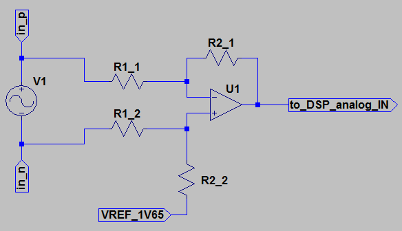
we would like to use the PGA with AC signals.

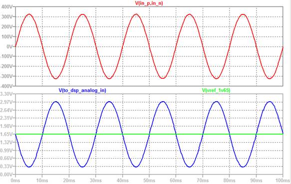
Typically, they have a 1.65V offset and a +-1.65V amplitude to reach the max. 3.3V ADC input.

If we now want to measure a signal with 1.65V offset and only 0.2V amplitude, this does not seem to be possible with the current PGA.
We would have to adjust the offset according to the PGA scale.
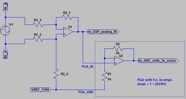
In addition, the PGA Gain cannot be chosen to be 1 as 3 is the lowest amplification.

The PGA_GND has to be in -50..200mV range - we would need it at 1.65V for the AC signals.

This makes the PGA not suited for AC signals.

Any hints or solutions? Or do we have to wait for this feature to be implemented in a future device?

  • Hi Stephan,

    I'll get back to you on this tomorrow.
  • Hi Stephen,

    The PGA voltage amplification is done with respect to ground and not around some virtual offset. This is how amplifiers work by definition. Instead of thinking of your signal as a 0.2V pk-pk AC signal with a 1.65V offset, you should think of it as a signal that varies from 1.55V to 1.75V because that's how the PGA will see it.

    Yes, the min gain for the PGA is 3x, 1x gain (voltage follower) is not supported. At the min gain, your 1.75V input will be 1.75V*3 = 5.25V which will rail at the VDDA voltage of 3.3V.

    If your signal is a truly periodic signal with a positive offset, then all you need to do is add a negative offset to push it down into the PGA input range which is roughly vdda/gain (a little less than that if you want good linearity). In your case, you need to add about a -1.1V offset to it. However, instead of doing that, you can use a series capacitor to completely remove the DC offset and then add some positive offset back in using the buffered DAC, resistors and PGA (we explain how you can achieve this in the PGA chapter of the TRM).

    Let us know if this is not clear.
  • Hi Frank,

    maybe I was not clear enough.

    This is how wo are doing ADC on AC signals today:

    This results in a signal centered around 1.65V, with an amplitude of 1.65V (here for 400V AC):

    If we want to use the PGA and switch the amplification DYNAMICALLY to adjust the fullscale range, we would like to keep our offset of 1.65V and

    Zoom to 133Vpk with PGA ampl. equal to 3

    Zoom to 66Vpk with PGA ampl. equal to 6

    Zoom to 33Vpk with PGA ampl. equal to 12

    This would be possible if the PGA GND_REF could be at 1.65V:

    Without this, we have to change our external OP offset together with the PGA gain.

    We can't remove the DC offset completely via capacitor because we have to detect DC offset in the signal.

    Do you agree that all this makes the use of the PGA for AC signals hard ?

    Because of this I proposed a GND_REF of up to 1.65V for a future device...

    Regards, Stephan

  • Just as addition: Can you explain the restriction of PGA_GND to max. 200mV? I see no reason for this because we do not leave the 0..3.3V range.
  • Hi Stephen,

    Thanks for supplying the extra details, I think I understand your problem a little better now. I tend to think of signals going into the PGA a little differently:
    1. Pure DC signals.
    2. Pure AC signals.
    3.(AC+DC) signals for which you don't care about the DC in which case the DC can be easily removed.
    4.(AC+DC) signals for which you care about both. For these types of signals, from the PGAs perspective, I don't think of them as a AC signal with a DC offset but rather a complete signal. I believe this is where your use-case falls into.
    For this, you'll have to divide down your whole signal with resistors if it's not in the valid PGA range before gaining by the PGA since you care about both. Have you considered this?
    Not sure how much leeway you have in your application but another option will be to measure the AC and DC separately. Use a capacitor to remove the DC and use an inductor to remove the AC and measure the 2 signals on 2 channels.

    Nevertheless, we currently don't think this is a typical use-case but that could obviously change as the PGA has had time to mature in the market. If that assumption ends up not holding anymore, we will explore removing the PGA_GND restriction on a future PGA.

    On the question of why the restriction on PGA_GND: This is because of how some of the internal structures are designed. The diagram in the TRM is a functional diagram and not necessarily how the PGA is implemented. There is of course nothing that physically prevents you from doing that but since it would fall under the umbrella of using the PGA out of specification, non of the specifications in the datasheet will apply.

    One parting question: From one of your screen captures, "to_dsp_analog_in" is shown as full-scale, going from about 0.33V to 2.97V. If your signal is already full-scale, why do you need to go through the PGA? Is this just for buffering.
  • Hi Frank,

    regarding your last question:
    The screen capture shows our actual design, with max. "to_dsp_analog_in" from 0 to 3.3V.
    But this signal can vary and can also be a lot smaller - this is where we would like to use the PGA to do not loose resolution as we do now.

    As I understand, you might consider our PGA_GND proposal for a future design, so that's all we can expect for the moment.

    Regards,
    Stephan