This thread has been locked.

If you have a related question, please click the "Ask a related question" button in the top right corner. The newly created question will be automatically linked to this question.

TMS320F28032: DAC Setting time and How to measure it

Part Number: TMS320F28032

Hi Team,

   Could you kindly help give comments for DAC peripheral:

   1)  Definition on Setting time for F28032 internal 10-bit DAC?

    2) How to measure the setting time? 

    3) Factors which could impact the setting time?

   Expect for your reply, thanks.

Best Regards

Benjamin

  • Benjamin,

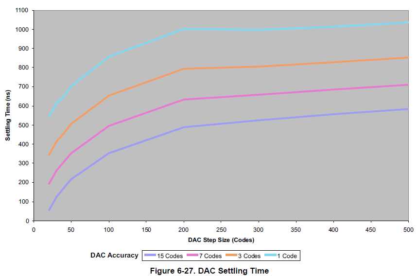
    You can refer to the DAC Settling Time plot in the datasheet:

    The major factors for settling time are

    1. The accuracy required -- shown for 15, 7, 3, and 1 code(s), and
    2. The magnitude of output change -- shown for ~20 to 500 codes

    There is no direct way of measuring the DAC output.  Instead, you would need to find the DC input voltage that produces a comparator trip for a DAC code (X).  With the same DC input voltage, you can then measure the amount of time that it takes to produce a comparator trip when changing the DAC code from a new value of (Y) back to (X).

    -Tommy

  • Hi Tommy,
    According to your recommended method, we take DC input which was 1013(LSB) voltage to connect comparator A, while configure DAC output to comparator B. Then we set the DAC output value by 0 -> 1023 -> 0 -> 1023 , look at the comparator output state to indirectly test this time, found that 0->1013 (corresponding comparator output low ) the actual time is 60~70ns, and 1023~ 1013 (corresponding comparator output high power usual) the actual time is 20ns, how to explain this phenomenon?
    Is there have voltage ripple during DAC setting time?

    Thanks!
  • BM,

    I don't understand the concern. What behavior are you expecting? Perhaps a figure would help.

    -Tommy
  • Hi Tommy,
    The concern is that when changing the DAC code from a new value of (0) back to (1023), the time it takes to produce a comparator trip was 60~70ns. This time is far less than what figure 6-27 DAC setting time provided.
    How to explain this phenomenon?
    Thanks~
  • Hi Tommy,

      The Setting time from WIKI is shown as below figure,  Could you kindly give comments for how to understand the 15codes/7codes/3codes/1codes for the accuracy? and how the accuracy link to the setting time?

     Also as you mentioned for the measurement, could you kindly give comments for the BM's measurement for the valid or invalid?

      Expect for your reply, thanks.

  • BM,

    The chart includes behavior from pessimistic scenarios that may affect settling time. For example, devices with weaker DAC drive strengths, but are still within manufacturing tolerances.

    There is nothing wrong with having the DAC settle faster than what is shown in the chart. The concern would only be when the DAC settles slower than what is shown.

    -Tommy
  • Benjamin,

    Your attachment is not showing up for me.

    When the DAC value is changed, the rate of change on the output looks something like a capacitor charging curve. The bulk of the output shift happens quickly, but the rate of change slows as it nears the target voltage.

    If the system can operate normally with +/- 15 code accuracy, then the settling time can be considered to be quicker than if the required accuracy is +/- 1 code. The output curve looks the same in either case, but the +/- 15 threshold is reached quicker than the +/- 1 threshold.

    -Tommy