


Part Number: TMS320F28379D
Greetings,
I'm using the F28379D Launchpad to do some testing right now. I've initialized ADC A and ADC C to 16-bit differential modes. According to the launchpad data sheet, all ADCs are referenced at 3V and GND. I have also verified these voltages with a probe.
The ADCs have all been initialized the same way, but with different ePWM triggers. Each ADC fills up it's own DMA buffer. ADC A has two active channels that alternate their SOCs.
The input data is a sine wave at varying low frequencies (100 - 1000Hz), with a Vpp of 3V. No DC bias.
I have two questions:
1) My ADC Results for two channels are clipping/saturating at certain integer values, why is that?
My current guess right now is that the signal I'm feeding the ADCs is not in compliance with the calibration/OTP settings on the device.
The following plots were generated by filling an array with ADC data and then saving that memory region to a text file, and then plotting with Python. (There also appears to be a consistent discontinuity in the sine wave, but I don't know what would be causing it.)
ADC Channels 0/1:

ADC A Channels 4/5:
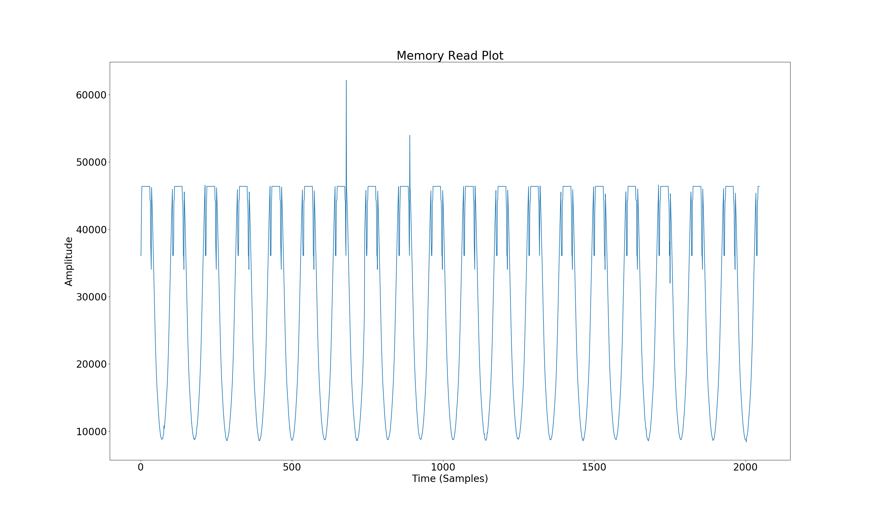
ADC C Channels 2/3:
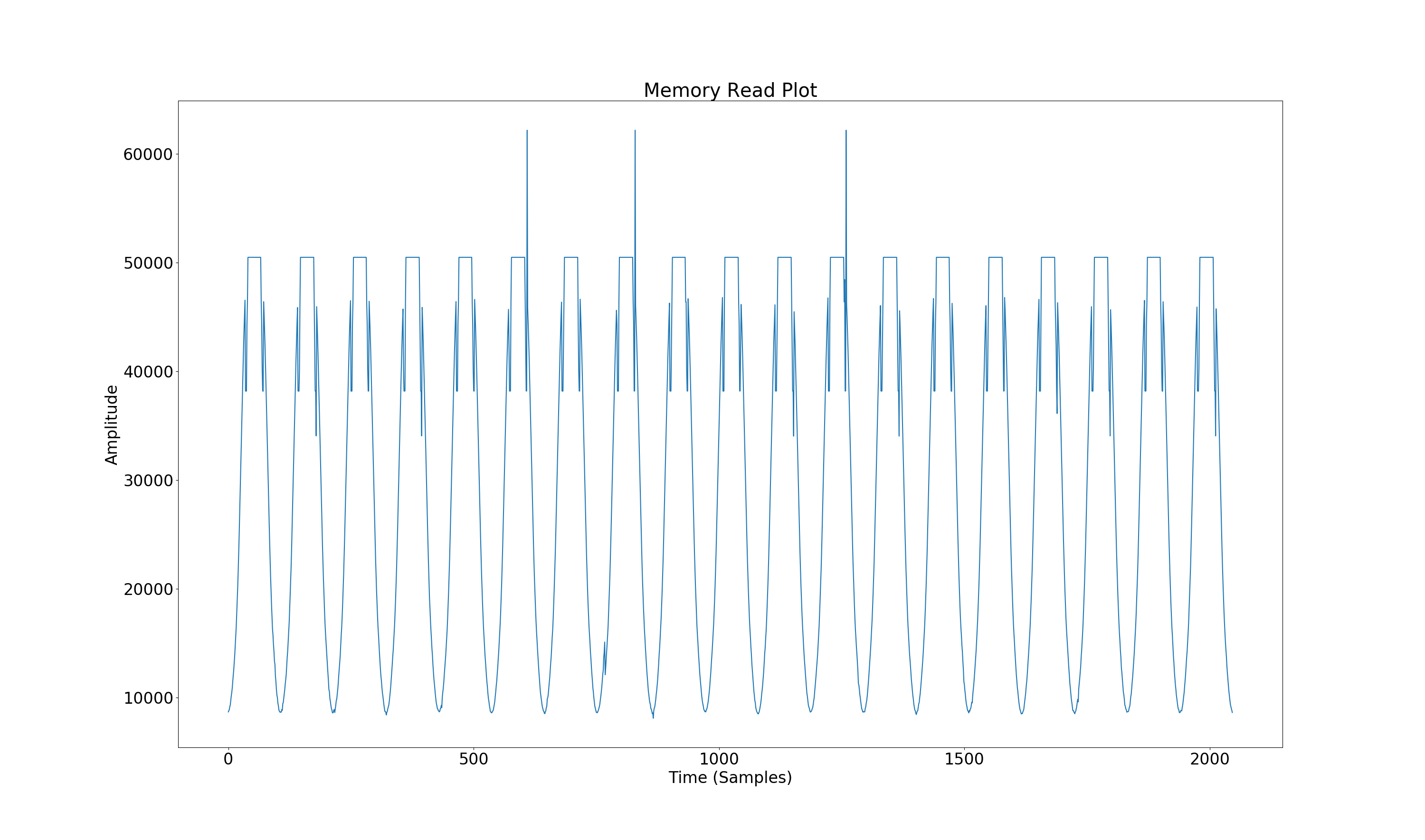
2) Signal going into ADC channels is bleeding/leaking over to other ADC channels/ADCs, how do I mitigate this effect?
I think this is a trade-off of chip ADCs with minimal isolation, but the signal leakage is surprisingly large.
Thank You


