This thread has been locked.

If you have a related question, please click the "Ask a related question" button in the top right corner. The newly created question will be automatically linked to this question.

CCS/LAUNCHXL-F28379D: Possible signal path through the eCAP module

Part Number: LAUNCHXL-F28379D
Other Parts Discussed in Thread: C2000WARE

Tool/software: Code Composer Studio

Hello,

my input X-BAR outputs INPUT1 ... 6 are used for other tasks.

Therefore my questions:

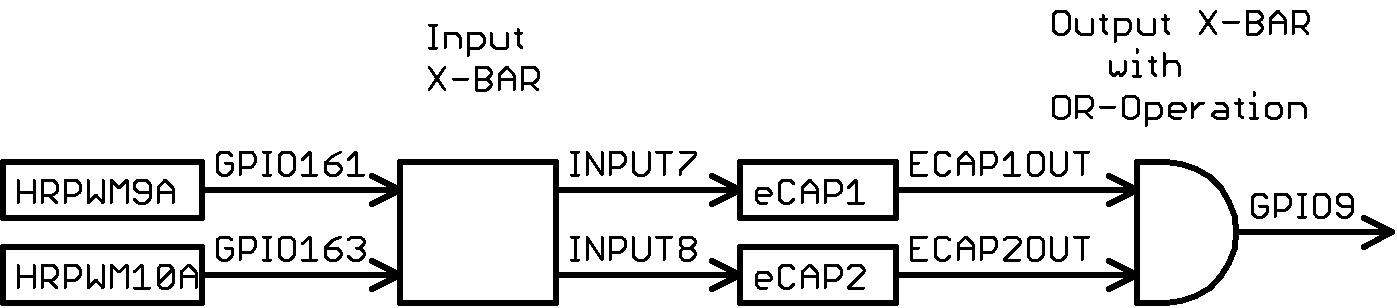
Is the shown signal path possible without changing the signal between INPUT7 and ECAP1OUT (respectively INPUT8 and ECAP2OUT)?

If so, how do I configure eCAP1 and eCAP2?

  • Hi Magic Ball,

    The ECAP has only one input/output pin. In capture mode, it's an input and in epwm mode, it's an output.

    For input mode, you will need to use the input xbar register -> InputXbarRegs.INPUTxSELECT (x is 7 for ecap1 and 8 for ecap2 like you have in your diagram)

    For output mode, you will need to use the output xbar registers OutputXbarRegs.OUTPUTxMUX0TO15CFG and OutputXbarRegs.OUTPUTxMUXENABLE. You can pick any of the output xbars. You will of course need to also configure the GPIO mux option to be the output xbar you choose.
  • Hi Frank,

    many thanks for your response.

    The signals on GPIO161 and GPIO163 are okay, I checked them.
    At GPIO9 but no signal arrives. What did I misunderstand?
    Do I have to set something else in the eCAP module?

    EALLOW;
    InputXbarRegs.INPUT7SELECT = 161; //= HRPWM9A (on GPIO161)
    InputXbarRegs.INPUT8SELECT = 163; //= HRPWM10A (on GPIO163)
    OutputXbarRegs.OUTPUT6MUX0TO15CFG.bit.MUX0 = 3; // Select ECAP1 on Mux0
    OutputXbarRegs.OUTPUT6MUXENABLE.bit.MUX0 = 1; // Enable MUX0 for ECAP1
    OutputXbarRegs.OUTPUT6MUX0TO15CFG.bit.MUX2 = 3; // Select ECAP2 on Mux2
    OutputXbarRegs.OUTPUT6MUXENABLE.bit.MUX2 = 1; // Enable MUX2 for ECAP2
    GpioCtrlRegs.GPAMUX1.bit.GPIO9 = 3; // Select OUTPUTXBAR6 on GPIO9
    GpioCtrlRegs.GPAGMUX1.bit.GPIO9 = 0; // Select OUTPUTXBAR6 on GPIO9
    EDIS;

    Best regards,
    Martin
  • Martin,

    The configuration looks right but as i mentioned in the prior post, the ECAP can only operate in one of the two modes (input or output) at a time. Did you set the ECCTL2.bit.CAP_APWM to 1 for output mode. Also, how are you configuring the ECAP in either of the modes?
  • At ECCTL1 and ECCTL2 I have now made a lot of different settings. Unfortunately I did not get the desired result on GPIO9.

    One of many non-working settings as an example:     

         EALLOW;
         ECap1Regs.ECCTL1.bit.CAPLDEN = EC_DISABLE;
         ECap1Regs.ECCTL2.bit.CAP_APWM = EC_CAP_MODE;
         ECap1Regs.ECCTL2.bit.CONT_ONESHT = EC_ONESHOT;
         ECap1Regs.ECCTL2.bit.SYNCO_SEL = EC_CTR_PRD;
         ECap1Regs.ECCTL2.bit.SYNCI_EN = EC_DISABLE;
         ECap1Regs.ECCTL2.bit.TSCTRSTOP = EC_FREEZE;
         ECap1Regs.ECCTL2.bit.APWMPOL = EC_ACTV_LO;

         ECap2Regs.ECCTL1.bit.CAPLDEN = EC_DISABLE;
         ECap2Regs.ECCTL2.bit.CAP_APWM = EC_CAP_MODE;
         ECap2Regs.ECCTL2.bit.CONT_ONESHT = EC_ONESHOT;
         ECap2Regs.ECCTL2.bit.SYNCO_SEL = EC_CTR_PRD;
         ECap2Regs.ECCTL2.bit.SYNCI_EN = EC_DISABLE;
         ECap2Regs.ECCTL2.bit.TSCTRSTOP = EC_FREEZE;
         ECap2Regs.ECCTL2.bit.APWMPOL = EC_ACTV_LO;

         InputXbarRegs.INPUT7SELECT = 161;                                   //= HRPWM9A (on GPIO161)
         InputXbarRegs.INPUT8SELECT = 163;                                   //= HRPWM10A (on GPIO163)
         OutputXbarRegs.OUTPUT6MUX0TO15CFG.bit.MUX0 = 3;    // Select ECAP1 on Mux0
         OutputXbarRegs.OUTPUT6MUXENABLE.bit.MUX0 = 1;        // Enable MUX0 for ECAP1
         OutputXbarRegs.OUTPUT6MUX0TO15CFG.bit.MUX2 = 3;    // Select ECAP2 on Mux2
         OutputXbarRegs.OUTPUT6MUXENABLE.bit.MUX2 = 1;        // Enable MUX2 for ECAP2
         GpioCtrlRegs.GPAMUX1.bit.GPIO9 = 3;                                  // Select OUTPUTXBAR6 on GPIO9
         GpioCtrlRegs.GPAGMUX1.bit.GPIO9 = 0;                               // Select OUTPUTXBAR6 on GPIO9
         EDIS;

    The output usually showed only a dependency on APWMPOL. The signals ECAPx (= INPUTx of the input X-BAR) and ECAPxOUT (see Figure 16-1. and 16-2. in the TRM) can obviously not be directly connected.

    Is there still a good idea that I have not had yet?

  • Martin,

    I think you are still missing the point a bit. The code you posted is setting up the ECAP module in capture mode and in capture mode, you won't get any output.

    We have 2 examples in C2000Ware that will get you almost where you need to be.
    1. ECap_apwm example -> This sets up the ECAP module in epwm mode and outputs on GPIO5.
    2. ECap_Capture_Pwm example -> This sets up the ECAP module in capture mode to record the output of a separately configured EPWM.

    Please give these 2 examples a try and along with documentation in the ECAP chapter of the TRM, it should make sense. Let us know if there is anything else we need to clarify.
  • Hello,

    in both examples, the eCAP module is controlled by the input signals. Here are the input signals and the output signals different.

    I would like, however, that the input signals are not changed by the eCAP modules.
    It is probably not possible.
  • Martin,

    No, that's not true. In the first example "ecap_apwm", the ECAP is setup as an output and it outputs it's signal through GPIO5. In the second example "ecap_capture_pwm", the ECAP is setup as an input through GPIO19.

    I'm not sure how you are seeing both examples as being configured as inputs. What you are looking to do can be accomplished by merging these 2 examples but as i mentioned before, the ECAP can only be in one of it's 2 modes at a time. You don't need to change the assigned GPIOs. If this is still not clear, do you mind pointing out where the confusion is?
  • Hello,

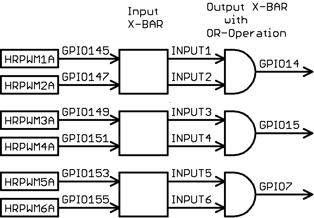
    the generation of the first three summation signals works very well:

    //
    // OR-Operation of HRPWM1A with HRPWM2A signals (with transfer to GPIO14)
    // and HRPWM3A with HRPWM4A signals (with transfer to GPIO15)
    // and HRPWM5A with HRPWM6A signals (with transfer to GPIO7)
    // and HRPWM9A with HRPWM10A signals (with transfer to GPIO9)
    //
    EALLOW;
    GpioCtrlRegs.GPEQSEL2.bit.GPIO145 = 3; // Asynch input GPIO145
    GpioCtrlRegs.GPEQSEL2.bit.GPIO147 = 3; // Asynch input GPIO147
    GpioCtrlRegs.GPEQSEL2.bit.GPIO149 = 3; // Asynch input GPIO149
    GpioCtrlRegs.GPEQSEL2.bit.GPIO151 = 3; // Asynch input GPIO151
    GpioCtrlRegs.GPEQSEL2.bit.GPIO153 = 3; // Asynch input GPIO153
    GpioCtrlRegs.GPEQSEL2.bit.GPIO155 = 3; // Asynch input GPIO155
    GpioCtrlRegs.GPFQSEL1.bit.GPIO161 = 3; // Asynch input GPIO161
    GpioCtrlRegs.GPFQSEL1.bit.GPIO163 = 3; // Asynch input GPIO163

    InputXbarRegs.INPUT1SELECT = 145; //= HRPWM1A (on GPIO145)
    InputXbarRegs.INPUT2SELECT = 147; //= HRPWM2A (on GPIO147)
    OutputXbarRegs.OUTPUT3MUX0TO15CFG.bit.MUX1 = 1; // Select INPUTXBAR1 on Mux1
    OutputXbarRegs.OUTPUT3MUXENABLE.bit.MUX1 = 1; // Enable MUX1 for INPUTXBAR1
    OutputXbarRegs.OUTPUT3MUX0TO15CFG.bit.MUX3 = 1; // Select INPUTXBAR2 on Mux3
    OutputXbarRegs.OUTPUT3MUXENABLE.bit.MUX3 = 1; // Enable MUX3 for INPUTXBAR2
    GpioCtrlRegs.GPAMUX1.bit.GPIO14 = 2; // Select OUTPUTXBAR3 on GPIO14
    GpioCtrlRegs.GPAGMUX1.bit.GPIO14 = 1; // Select OUTPUTXBAR3 on GPIO14

    InputXbarRegs.INPUT3SELECT = 149; //= HRPWM3A (on GPIO149)
    InputXbarRegs.INPUT4SELECT = 151; //= HRPWM4A (on GPIO151)
    OutputXbarRegs.OUTPUT4MUX0TO15CFG.bit.MUX5 = 1; // Select INPUTXBAR3 on Mux5
    OutputXbarRegs.OUTPUT4MUXENABLE.bit.MUX5 = 1; // Enable MUX5 for INPUTXBAR3
    OutputXbarRegs.OUTPUT4MUX0TO15CFG.bit.MUX7 = 1; // Select INPUTXBAR4 on Mux7
    OutputXbarRegs.OUTPUT4MUXENABLE.bit.MUX7 = 1; // Enable MUX7 for INPUTXBAR4
    GpioCtrlRegs.GPAMUX1.bit.GPIO15 = 2; // Select OUTPUTXBAR4 on GPIO15
    GpioCtrlRegs.GPAGMUX1.bit.GPIO15 = 1; // Select OUTPUTXBAR4 on GPIO15

    InputXbarRegs.INPUT5SELECT = 153; //= HRPWM5A (on GPIO153)
    InputXbarRegs.INPUT6SELECT = 155; //= HRPWM6A (on GPIO155)
    OutputXbarRegs.OUTPUT5MUX0TO15CFG.bit.MUX9 = 1; // Select INPUTXBAR5 on Mux9
    OutputXbarRegs.OUTPUT5MUXENABLE.bit.MUX9 = 1; // Enable MUX9 for INPUTXBAR5
    OutputXbarRegs.OUTPUT5MUX0TO15CFG.bit.MUX11 = 1; // Select INPUTXBAR6 on Mux11
    OutputXbarRegs.OUTPUT5MUXENABLE.bit.MUX11 = 1; // Enable MUX11 for INPUTXBAR6
    GpioCtrlRegs.GPAMUX1.bit.GPIO7 = 3; // Select OUTPUTXBAR5 on GPIO7
    GpioCtrlRegs.GPAGMUX1.bit.GPIO7 = 0; // Select OUTPUTXBAR5 on GPIO7


    but the generation of the fourth summation signal unfortunately still does not work (the signals on GPIO161 and GPIO163 are OK):

    ECap1Regs.ECCTL2.bit.CAP_APWM = EC_APWM_MODE;
    ECap2Regs.ECCTL2.bit.CAP_APWM = EC_APWM_MODE;
    InputXbarRegs.INPUT7SELECT = 161; //= HRPWM9A (on GPIO161)
    InputXbarRegs.INPUT8SELECT = 163; //= HRPWM10A (on GPIO163)
    OutputXbarRegs.OUTPUT6MUX0TO15CFG.bit.MUX0 = 3; // Select ECAP1 on Mux0
    OutputXbarRegs.OUTPUT6MUXENABLE.bit.MUX0 = 1; // Enable MUX0 for ECAP1
    OutputXbarRegs.OUTPUT6MUX0TO15CFG.bit.MUX2 = 3; // Select ECAP2 on Mux2
    OutputXbarRegs.OUTPUT6MUXENABLE.bit.MUX2 = 1; // Enable MUX2 for ECAP2
    GpioCtrlRegs.GPAMUX1.bit.GPIO9 = 3; // Select OUTPUTXBAR6 on GPIO9
    GpioCtrlRegs.GPAGMUX1.bit.GPIO9 = 0; // Select OUTPUTXBAR6 on GPIO9
    EDIS;

    I hope, I have implemented both of you examples correctly.
  • Martin,

    I'm very confused by your last post. What summation signals are you referring to? Are you sure you are referencing the 2 examples I pointed to earlier?
  • Hello Frank,

    sorry, it was perhaps a bit ambiguous, I mean an OR-operation between the output signals of HRPWM9A and HRPWM10A.

    I can not see, which relevant instructions I have not inserted from the two examples here?
  • Martin,

    No worries. Can you draw a new block diagram of what you are trying to achieve? because it looks like our conversion has deviated a bit from what you initially had in mind, looking at your first block diagram in the post.
  • Hello,

    the goal is to generate four signals, which are formed by OR-Operation of two HRPWM signals.

    The generation of the first three output signals are very well:

    I have considered the following way for the generation of the fourth output signal:

    Unfortunately, this way does not work.

    I would still be happy about a suggested solution, how to produce the fourth output signal.

  • Hi Martin,

    Thanks for providing the updated diagram, that definitely helps clear things up. Currently away on business travel so will reply with an answer tomorrow or latest by Friday.
  • Hi Martin,

    Thanks for your patience. I understand your problem now. So your objective is to "OR" 2 HRPWM signals by going through the output xbar and really has nothing to do with the ECAP. I'm afraid the 4th signal won't work because the ECAP won't do a pass-through.
  • Hello Frank,

    although I had hoped, I could find no way to solve the problem in the microcontroller.

    Thank you very much for your help.

    Best regards,
    Martin