This thread has been locked.

If you have a related question, please click the "Ask a related question" button in the top right corner. The newly created question will be automatically linked to this question.

TMS320F280049: How to generate 8 paired PWM output like this

Part Number: TMS320F280049

Hello,

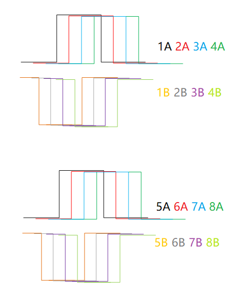
My customer want to generate 8 paired PWM output like below picture to drive full bridge.

Black: 1A, Red: 2A, Blue:3A, Green: 4A, Orange 1B, Grey: 2B, Purple:3B, Light green: 4B

The requirement is :

1. 50% duty cycle square wave, frequency is adjustable

2. It always has 90° phase shift between 1A and 1B.  2, 3, 4 waveform follow up 1A and 1B after a phase shift.

3. Adjustable phase difference between 2A and 1A, 3A and 2A, 4A and 3A.

4. Adjustable phase difference between 2B and 1B, 3B and 2B, 4B and 3B.

5. 5A, 6A, 7A, 8A is same with 1A, 2A, 3A, 4A.

6. 5B, 6B, 7B, 8B is same with 1B, 2B, 3B, 4B.


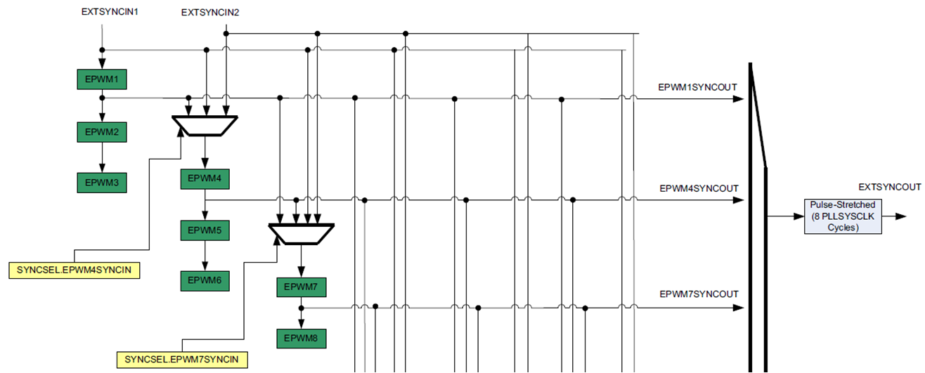
Could you let me know how to configure EPWM1 to EPWM8 while they are working on below 3 parallel mode?

  • Hello Daniel,

    Let's just look at PWMs 1, 2, 3 and 4.

    1. 50% duty cycle square wave, frequency is adjustable

    This is fairly straight-forward. You can configure each PWM module in up-count mode and generate 50% duty cycle using a CMPA match. CMPA value should be changed everytime the TBPRD (frequency) changes.

    2. It always has 90° phase shift between 1A and 1B.  2, 3, 4 waveform follow up 1A and 1B after a phase shift.

    I think having a 90 degree phase shift between A and B is the tricky part. But you can achieve this on 0049 by configuring the dead-band module as shown below and using equal RED and FED values that will give you 90 degree phase shift. 

    3. Adjustable phase difference between 2A and 1A, 3A and 2A, 4A and 3A.

    This is possible using the phase sync mechanism of the PWMs. phase shift between 4A and 3A,can be achieved by programming appropriate phase shift between 1A and 4A (3A and 1A has a defined phase relationship, which makes this possible).

    4. Adjustable phase difference between 2B and 1B, 3B and 2B, 4B and 3B.

    I don't understand how this is physically possible. There is a fixed 90 deg phase shift between all As and corresponding Bs. There is a programmable phase shift between all As with respect to each other. As a result you cannot have a separate adjustable phase shift between all Bs at the same time.

    PWMs 5, 6, 7 and 8 should be configured similarly.

    I hope this helps.

    Hrishi

  • Hi Hrishi,

    Thanks for your professional reply.

    Sorry to explain the requirement again with the red change, when forget to tell you that dead-band has been used for other function.

    1. 50% duty cycle square wave, frequency is adjustable

    2. It always has 90° phase shift between 1A and 1B.  2, 3, 4 waveform follow up 1A and 1B after a phase shift.

    It only require 90° phase shift between 1A and 1B. Don't need  90° phase shift between 2A and 2B, 3A and 3B, 4A and 4B.

    3. Adjustable phase difference between 2A and 1A, 3A and 1A, 4A and 3A.

    4. Adjustable phase difference between 2B and 1B, 3B and 1B, 4B and 3B.

    5. Complementation dead zones between 5A, 6A, 7A, 8A and 1A, 2A, 3A, 4A separately.

    6. Complementation dead zones between 5B, 6B, 7B, 8B and 1B, 2B, 3B, 4B  separately.

  • Hi Daniel,

    Thanks for the clarification. It seems like what you would need are twice the number of PWM modules. However, as we each PWM module on this device has two outputs which share the same time-base, there are somethings that will need to be done in software to achieve this.

    For #2 and #4, the 2B, 3B, 4B signal could be generated the same way as I described earlier (using the dead-band sub-module). To achieve programmable phase-shift between all the B channels, the software will have to take the phase shift between A channels into account, and accordingly adjust RED and FED delays of these PWMs to get desired phase shifts between the slave Bs and 1B (knowing that 1B is always 90 deg phase shifted with respect to 1A).

    For #5 and #6, the software will need to calculate the compare register (CMPA/B) values for each PWM module and adjust the CMPA/B values separately to account for the phase shift and the dead-band requirement. Hardware inversion + dead-band is not possible in this case.

    Hrishi

  • Hi Hrishi,

    Do we have to utilize dead zone to achieve this?
    To achieve 5, 6, 7, 8 dead zone vs 1, 2, 3, 4., is it achieved by adjust CMPA and CMPB ?
    5,6,7,8 module is different from 1,2,3,4. How to select the synchronous clock?
    Thanks a lot.
  • Hi Daniel,

    To achieve phase shift between 1A and 1B, you will need to use the dead-band sub-module.

    Yes, 5, 6, 7, 8 Vs 1, 2, 3, 4 dead-band may be achieved by adjusting CMPA and/or CMPB values for each module separately taking its phase shift, duty cycle and required dead-time into account.

    I believe having PWM1 module as the master source for sync should work. Do you mean to say that 5,6,7,8 are completely independent of 1,2,3,4 i.e. no phase shift? If that's the case, PWM5 has to be made the master for this 2nd chain (5,6,7,8).

    Hrishi

  • Hi Hrishi,

    Thanks very much for your help. We will try it.