This thread has been locked.

If you have a related question, please click the "Ask a related question" button in the top right corner. The newly created question will be automatically linked to this question.

CCS/TIDM-HV-1PH-DCAC: gridconnectedinvlclfltr.c doubts

Part Number: TIDM-HV-1PH-DCAC
Other Parts Discussed in Thread: C2000WARE-DIGITALPOWER-SDK, CONTROLSUITE

Tool/software: Code Composer Studio

Hello everyone, I was going through the "Grid Connected Inverter Design Guide"-- " Tidu21a". 

In the code "gridconnectedinvlclfltr.c" there is a line 

 652  ----------  invDutyPU= (cntl2p2z_LeadLag_vars.Out + invVoInstSD)/(invVbusInst*(VDCBUS_MAX_SENSE/VDC_NOMINAL));

1. What quantity does  "invVoInstSD" represents as there's no mention of this variable throughout the code and how does it effects the control part.

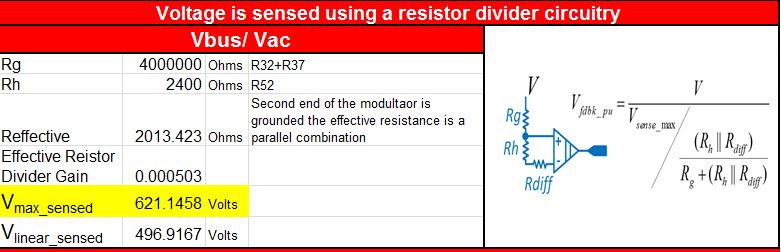
2. Why VDCBUS_MAX_SENSE is kept to 620.152 in Settings file. How we came with up this value and what role does it play here as during general functioning(correct me if I'm wrong here)  invVbusInst would be 380V and VDC_NOMINAL would also be 380V so the whole equation would just be divided by this 620.152 quantity.

Regards 

Archit 

  • Archit, 

    Please refer to the new code in C2000Ware-DigitalPower-SDK, you are referring to the code in controlSUITE and that is a not maintained branch of the code. 

    Can you refer to the new code and see if the concerns persist? 

    you will see the below

    invDutyPU= (gi_lead_lag_out + invVoInst)/
    (invVbusInst*(VDCBUS_MAX_SENSE/VDC_NOMINAL));

    The scaling for VDCBUS_MAX_SENSE is done because the controller is tuned for VDC_NOMINAL. As the sense scaling is for a higher range in this design, we need to scale the Vbus variable appropriately. 

    Also, it enables one more option that we can use the same scaling for the Vbus and Vac by emulating this and avoids extra scalars in the control loop model. 

  • Hi Manish ,

    I went through the code in  C2000Ware-DigitalPower-SDK  and my issues regarding the variables(name) mentioned in code are resolved.

    Just want to ask why we need voltage feedforward in PR control structure ? . As far as I have read it is used in PI based  current controller  to reduce/remove the steady state error.

    Also, my previous doubt --Why VDCBUS_MAX_SENSE is kept to 620.152 in Settings file?. Is it related to the V max sensed value calculated in the Excel sheet(Attached) . The value calculated there is 621.1458V. 

    Regards

    Archit

  • Archit,

    it depends on the control designer, i saw the feed forward to improve the phase slightly and hence used it on this design. If you prefer not to use it you can change the code and re-test for your design.

    Before I answer your question on the sense scale, can you identify if you are interested in the ADC sense option or the SDFM sense option?

    Regards
    Manish
  • Hi Manish,
    I am familiar with the normal/SAR ADC option and don't have much info about the SDFM. Right now, I was just trying to make sense about the 620.152 value used in the MAX_SENSE.

    Also, I need your opinion in one regard. I am trying to design a 3-4KVA Solar PV grid tied inverter and I was going through the available application/ design sheets and I found the following-

    1. Solar HV DC-AC Kit User Guide_Rev1.0 --- It uses PI control structure as current controller (quite old document).
    2.SolarExplorer_v1.1-- It also uses PI control structure as current controller(Low power,Low voltage)
    3.HV_1PH_DCAC-- It uses PR+HC+PI in current controller ( High voltage-380V , Low power-400VA)
    4.TMDSSOLARUINVKIT_v100- Microinverter -----Uses 3p3Z as current controller.

    Which of the above current controller can I use if I want to scale up the Power output as in my case(3-4kVA)

    Regards
    Archit
  • Archit,

    It depends on the switching frequency you will have.

    If you switching frequency is very high > 50kHz , inductor is smaller and one can push through enough bandwidth through the loop for a good grid connection results.

    Ignore what is on the solar explorer kit as that is very old. Also HV-DC-AC uses PI but also uses voltage feed forward to simlify the current loop.

    The solar u inv kit uses similar to HV DC-AC, but accounts for the LCL resonance. You could potentially put a passive res in the C branch and damp it. Then the control is exactly as in HV DC-AC kit

    the HV-1PH-DCAC uses the technqiues that are used in higher power type converters , as the switching cannot be pushed higher one needs to use harmonic compensators. (note PR is similar to DQ domain PI)

    -Manish