Part Number: TMS320F28335
Other Parts Discussed in Thread: C2000WARE
Tool/software: Code Composer Studio
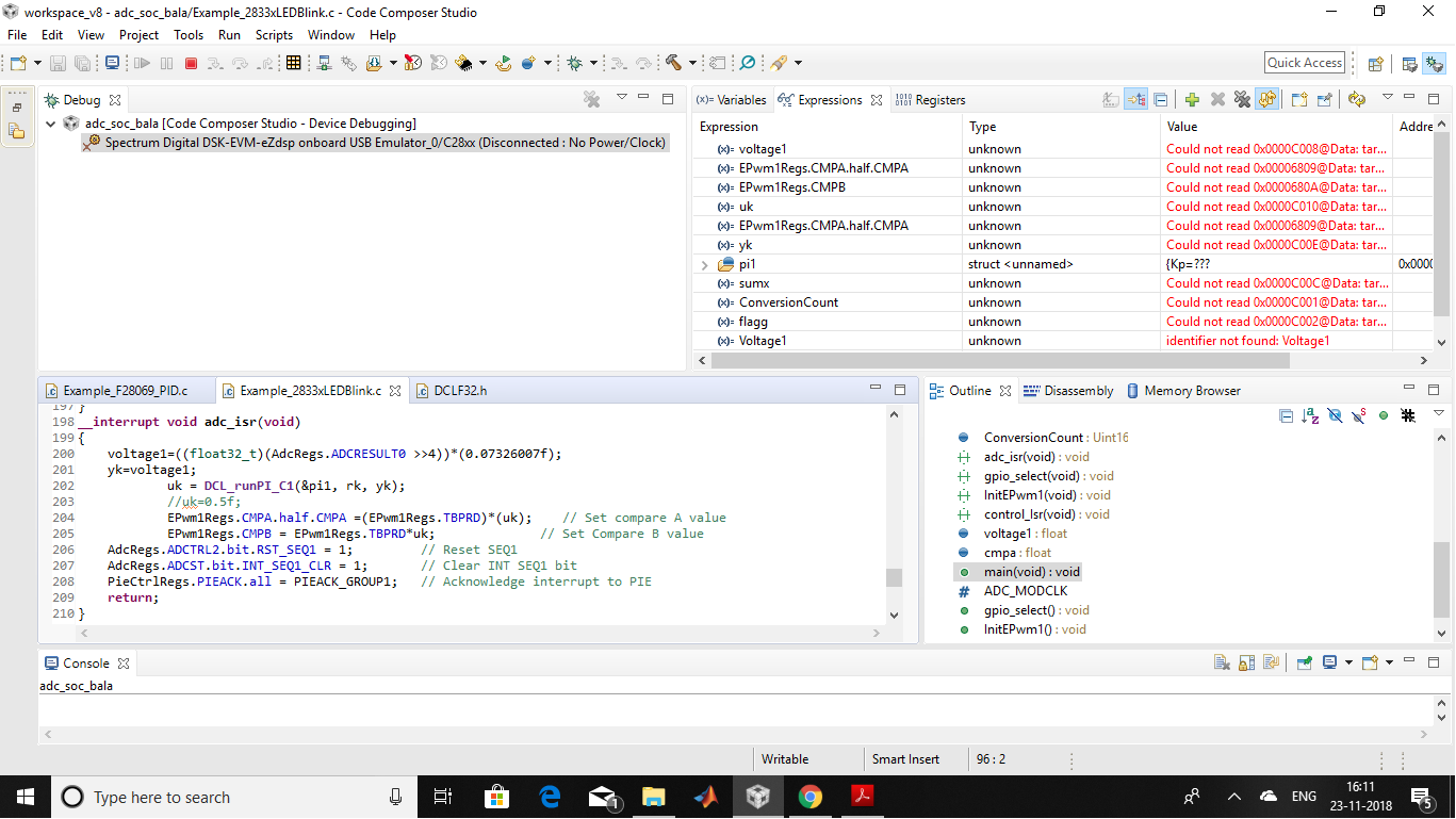
I am controlling the dc to dc boost converter using f28335. PI controller is implemented using DCL library. I want a reference voltage of 20 volts. I am converting the ADC value into volts first and multiplied by sensor gain of 100. Now, this ADC value and Required value is given to the PI controller. But the output is not changing. It is always saturated to its maximum value.
Please find the code attached with this mail.
#include "DSP28x_Project.h"     // Device Headerfile and Examples Include File
#include "DCL.h"
#include "DCLF32.h"
#include "DCL_fdlog.h"
#include "DCLC28.h"


float32_t rk = 20.0f;
float32_t yk;
float32_t lk;
float32_t uk;
float Duty;
DCL_PI pi1 = PI_DEFAULTS;

//
// Function Prototypes
//
Uint16 LoopCount;
Uint16 ConversionCount;
void adc_isr(void);
void gpio_select(void);
void InitEPwm1(void);
void control_Isr(void);


float voltage1;
float cmpa;


//
// Main
//
void main(void)
{
    InitSysCtrl();
    DINT;
    InitPieCtrl();
    EALLOW;
        #if (CPU_FRQ_150MHZ)     // Default - 150 MHz SYSCLKOUT
            //
            // HSPCLK = SYSCLKOUT/2*ADC_MODCLK2 = 150/(2*3)   = 25.0 MHz
            //
            #define ADC_MODCLK 0x3
        #endif
        #if (CPU_FRQ_100MHZ)
            //
            // HSPCLK = SYSCLKOUT/2*ADC_MODCLK2 = 100/(2*2)   = 25.0 MHz
            //
            #define ADC_MODCLK 0x2
        #endif
    EDIS;
    EALLOW;
        SysCtrlRegs.HISPCP.all = ADC_MODCLK;
    EDIS;
    IER = 0x0000;
    IFR = 0x0000;
    InitPieVectTable();

    EALLOW;         // This is needed to write to EALLOW protected registers
        PieVectTable.ADCINT = &adc_isr;
    EDIS;    // This is needed to disable write to EALLOW protected registers
    InitAdc();  // For this example, init the ADC

    gpio_select();
    InitEPwm1();

    PieCtrlRegs.PIEIER1.bit.INTx6 = 1;
    IER |= M_INT1;

       AdcRegs.ADCMAXCONV.all = 0x0001;       // Setup 2 conv's on SEQ1
       AdcRegs.ADCCHSELSEQ1.bit.CONV00 = 0x3; // Setup ADCINA3 as 1st SEQ1 conv.
       AdcRegs.ADCCHSELSEQ1.bit.CONV01 = 0x2; // Setup ADCINA2 as 2nd SEQ1 conv.

       /* initialise controller variables */
       pi1.Kp=2.0f;
       pi1.Ki=1.0f;
       pi1.Umax=0.8f;
       pi1.Umin=0.2f;

       rk = 20.0f;                             // initial value for control reference
       lk = 1.0f;                              // control loop not saturated

       //
       // Enable SOCA from ePWM to start SEQ1
       //
       AdcRegs.ADCTRL2.bit.EPWM_SOCA_SEQ1 = 1;

       AdcRegs.ADCTRL2.bit.INT_ENA_SEQ1 = 1;  // Enable SEQ1 interrupt (every EOS)

                            // control loop not saturated

    EINT;           // Enable Global interrupt INTM
    ERTM;           // Enable Global realtime interrupt DBGM
    for(;;);
}

//
// cpu_timer0_isr -
//

void gpio_select(){
        EALLOW;
        GpioCtrlRegs.GPAPUD.bit.GPIO0 = 0;   // Enable pullup on GPIO0
        GpioCtrlRegs.GPAPUD.bit.GPIO1 = 0;   // Enable pullup on GPIO0
        GpioCtrlRegs.GPAMUX1.bit.GPIO0 = 1;  // GPIO0 = PWM1A
        GpioCtrlRegs.GPAMUX1.bit.GPIO1 = 1;  // GPIO0 = PWM1A
        EDIS;

}
void InitEPwm1(){
        EPwm1Regs.TBCTL.bit.CTRMODE = 0; // Count up down
        EPwm1Regs.TBPRD = 3750;       // Set timer period
        EPwm1Regs.TBCTL.bit.PHSEN = TB_DISABLE;    // Disable phase loading
        EPwm1Regs.TBPHS.half.TBPHS = 0x0000;       // Phase is 0
        EPwm1Regs.TBCTR = 0x0000;                  // Clear counter
        EPwm1Regs.TBCTL.bit.HSPCLKDIV = 0x001;   // Clock ratio to SYSCLKOUT
        EPwm1Regs.TBCTL.bit.CLKDIV = 000;
        EPwm1Regs.TBCTL.bit.SYNCOSEL=1;
        EPwm1Regs.CMPA.half.CMPA =1875;    // Set compare A value
        EPwm1Regs.CMPB = 1875;              // Set Compare B value
        EPwm1Regs.CMPCTL.bit.LOADAMODE=1;
        EPwm1Regs.CMPCTL.bit.SHDWAMODE=0;
/*        EPwm1Regs.DBCTL.bit.OUT_MODE=3;
        EPwm1Regs.DBCTL.bit.POLSEL=2;
        EPwm1Regs.DBCTL.bit.IN_MODE=0;
        EPwm1Regs.DBRED=100;
        EPwm1Regs.DBFED=100;*/
        EPwm1Regs.AQCTLA.bit.ZRO=2;    // Set PWM1A on Zero
        EPwm1Regs.AQCTLA.bit.CAU=1;

            EPwm1Regs.ETSEL.bit.SOCAEN = 1;     // Enable SOC on A group
            EPwm1Regs.ETSEL.bit.SOCASEL = 1;    // Select SOC from from CPMA on upcount
            EPwm1Regs.ETPS.bit.SOCAPRD = 1;     // Generate pulse on 1st event

}
__interrupt void adc_isr(void)
{
    yk=(AdcRegs.ADCRESULT0 >>4)*300.0f/4095.0f;

    //Voltage2[ConversionCount] = AdcRegs.ADCRESULT1 >>4;
    //DCL_runClamp_C1(float *data, float Umax, float Umin);
    //


    lk=0.0f;
    uk = DCL_runPI_C1(&pi1, rk, yk);
    if (uk>0.8f){
        uk=0.8f;
    }
    else if (uk<0.1f){
        uk=0.1f;
    }
    //uk=0.5f;

    EPwm1Regs.CMPA.half.CMPA =(EPwm1Regs.TBPRD)*uk;    // Set compare A value
    EPwm1Regs.CMPB = EPwm1Regs.TBPRD*uk;              // Set Compare B value
    // If 40 conversions have been logged, start over
    //
    //
    // Reinitialize for next ADC sequence
    //
    AdcRegs.ADCTRL2.bit.RST_SEQ1 = 1;         // Reset SEQ1
    AdcRegs.ADCST.bit.INT_SEQ1_CLR = 1;       // Clear INT SEQ1 bit
    PieCtrlRegs.PIEACK.all = PIEACK_GROUP1;   // Acknowledge interrupt to PIE

    return;
}