Part Number: LAUNCHXL-F28379D
Other Parts Discussed in Thread: ADS1259
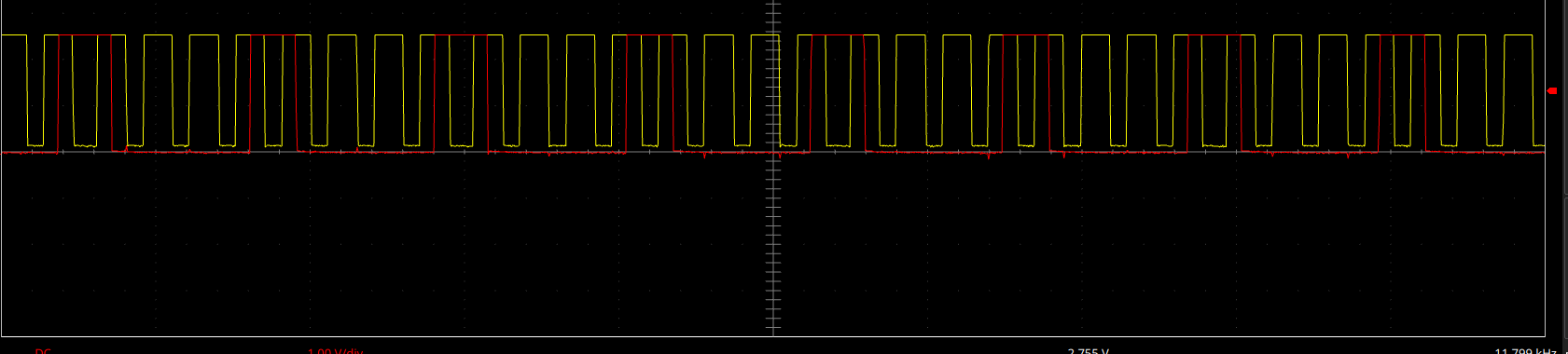
i'm trying to connect ADS1259 to LAUNCHXL-F28379D via hardware SPI. I have working implementation of communication protocol via software SPI, and now i'm trying to replace software SPI read/write to hardware ones. So, problems is: lock on SPI_readDataBlockingNonFIFO() on second or third iteration, and anyway it's returns not correct data. In loopback mode it's works, but sometimes locks too(i dont understent how in possible, what it waiting for? software implementation have no such problem).
details:
standart init.

//
// Initialize device clock and peripherals
//
Device_init();

//
// Disable pin locks and enable internal pullups.
//
Device_initGPIO();

//
// Initialize PIE and clear PIE registers. Disables CPU interrupts.
//
Interrupt_initModule();

//
// Initialize the PIE vector table with pointers to the shell Interrupt
// Service Routines (ISR).
//
Interrupt_initVectorTable();

GPIO_setPadConfig(76, GPIO_PIN_TYPE_PULLUP); //START
GPIO_setPinConfig(GPIO_76_GPIO76);

GPIO_setPadConfig(111, GPIO_PIN_TYPE_PULLUP); //DATA READY
GPIO_setPinConfig(GPIO_111_GPIO111);

GPIO_setPadConfig(60, GPIO_PIN_TYPE_PULLUP); //RESET
GPIO_setPinConfig(GPIO_60_GPIO60);

/////////////////////////////
GPIO_setPadConfig(0, GPIO_PIN_TYPE_PULLUP); //GREEN LED
GPIO_setPinConfig(GPIO_0_GPIO0);
GPIO_setDirectionMode(0, GPIO_DIR_MODE_OUT);

GPIO_setPadConfig(1, GPIO_PIN_TYPE_PULLUP); //RED LED
GPIO_setPinConfig(GPIO_1_GPIO1);
GPIO_setDirectionMode(1, GPIO_DIR_MODE_OUT);

GPIO_setPadConfig(2, GPIO_PIN_TYPE_PULLUP); //BLUE LED
GPIO_setPinConfig(GPIO_2_GPIO2);
GPIO_setDirectionMode(2, GPIO_DIR_MODE_OUT);

GPIO_setPadConfig(3, GPIO_PIN_TYPE_PULLUP); //TRANS LED
GPIO_setPinConfig(GPIO_3_GPIO3);
GPIO_setDirectionMode(3, GPIO_DIR_MODE_OUT);

#define SPI_BASE SPIB_BASE

//SPI
#if USE_HARDWARE_SPI
GPIO_setPadConfig(63, GPIO_PIN_TYPE_PULLUP);
GPIO_setPadConfig(64, GPIO_PIN_TYPE_PULLUP);
GPIO_setPadConfig(65, GPIO_PIN_TYPE_PULLUP);

GPIO_setPinConfig(GPIO_63_SPISIMOB);
GPIO_setPinConfig(GPIO_64_SPISOMIB);
GPIO_setPinConfig(GPIO_65_SPICLKB);

GPIO_setQualificationMode(63, GPIO_QUAL_ASYNC); // asynch input
GPIO_setQualificationMode(64, GPIO_QUAL_ASYNC); // asynch input
GPIO_setQualificationMode(65, GPIO_QUAL_ASYNC); // asynch input
#else
GPIO_setPadConfig(64, GPIO_PIN_TYPE_PULLUP); //MISO
GPIO_setPinConfig(GPIO_64_GPIO64);

GPIO_setPadConfig(63, GPIO_PIN_TYPE_PULLUP); //MOSI
GPIO_setPinConfig(GPIO_63_GPIO63);

GPIO_setPadConfig(65, GPIO_PIN_TYPE_PULLUP); //CLOCK
GPIO_setPinConfig(GPIO_65_GPIO65);

ads_device.spi_port.spi_sclk_pin = 65;
ads_device.spi_port.spi_mosi_pin = 63;
ads_device.spi_port.spi_miso_pin = 64;
ads_device.spi_port.period = 11;
#endif

SPI init

int init_spi_port(spi_port_t* spi_port)
{
int err = 0;
#if USE_HARDWARE_SPI
// Must put SPI into reset before configuring it
//
SPI_disableModule(SPI_BASE);
//
// SPI configuration. Use a 1MHz SPICLK and 16-bit word size.
//
SPI_setConfig(SPI_BASE, DEVICE_LSPCLK_FREQ, SPI_PROT_POL0PHA1,
SPI_MODE_MASTER, 1000000, 8);

SPI_disableFIFO(SPI_BASE);


SPI_setEmulationMode(SPI_BASE, SPI_EMULATION_STOP_AFTER_TRANSMIT);


//
// Configuration complete. Enable the module.
//
SPI_enableModule(SPI_BASE);


EINT;
ERTM;

#else
GPIO_setDirectionMode(spi_port->spi_sclk_pin, GPIO_DIR_MODE_OUT);
GPIO_setDirectionMode(spi_port->spi_mosi_pin, GPIO_DIR_MODE_OUT);
GPIO_setDirectionMode(spi_port->spi_miso_pin, GPIO_DIR_MODE_IN);
#endif
return err;
}

void write_spi_byte(spi_port_t* spi_port, uint16_t byte)
{
#if USE_HARDWARE_SPI
SPI_writeDataBlockingNonFIFO(SPI_BASE, byte);
#else
uint16_t si = 0;
for(si = 0; si < 8; si ++)
{
GPIO_WRITE(spi_port->spi_sclk_pin, 1);
byte&0x80 ? GPIO_WRITE(spi_port->spi_mosi_pin, 1) : GPIO_WRITE(spi_port->spi_mosi_pin, 0);
byte <<= 1;
half_spi_clock;
GPIO_WRITE(spi_port->spi_sclk_pin, 0);
half_spi_clock;
}
#endif
}

inline uint16_t read_spi_byte(spi_port_t* spi_port)
{
uint16_t byte = 0;
#if USE_HARDWARE_SPI
byte = SPI_readDataBlockingNonFIFO(SPI_BASE);
byte = __byte(&byte, 1);
#else

uint16_t si = 0;
int bit = 0;
for(si = 0; si < 8; si ++)
{
GPIO_WRITE(spi_port->spi_sclk_pin, 1);
byte <<= 1;
half_spi_clock;
GPIO_WRITE(spi_port->spi_sclk_pin, 0);
half_spi_clock;
bit = GPIO_READ(spi_port->spi_miso_pin);

byte = bit ? byte|0x01 : byte&0xfe;
}
#endif
return byte;
}