This thread has been locked.

If you have a related question, please click the "Ask a related question" button in the top right corner. The newly created question will be automatically linked to this question.

CCS/LAUNCHXL-F28379D: Using eQEP on F28379D Launchpad to read a quadrature encoder

Part Number: LAUNCHXL-F28379D


Tool/software: Code Composer Studio

Hello,

I'm trying to use either CCS or Simulink to read a quadrature encoder via eQEP and I am trying to use the headers on the f28379d launchpad that are labeled as QEP-A. The default pin assignments in the control suite project "eqep_pos_speed_cpu01" are GPIO 20-23. However, there is no map for these headers to their GPIO assignments in any of the manuals relating to the launchpad (there is no mapping in the cpu manual, the f28379d, or even the users guide).

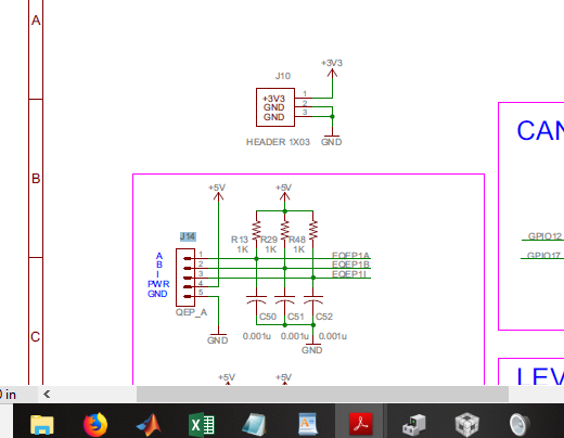
What GPIO pins does the QEP-A pin row (J14) correspond to? I tried connecting a quadrature encoder according to the attached diagram I found in the user guide and using Simulink (with these pin assignments) to program eQEP-A, but it was only returning the number 17 for some reason.

Any help you can provide would be greatly appreciated.

Thanks,

Tyler A

  • Hi Tyler,

    I've assigned your e2e thread to the eQEP expert, but in the meantime you might take a look at the F2837xD datasheet (www.ti.com/.../tms320f28377d.pdf) table "Table 4-3. GPIO Muxed Pins" which shows you which GPIOs the various peripheral functions are mapped to. If you can find the name of the QEP signals that appear on GPIO20-23 you can ctrl-f in the table to find the other alternate mappings, one of which is presumably what you QEP header is connected to.
  • I mean I guess I could just try them all, but its pretty frustrating that there's no diagram out there that shows all the pin muxing options that correspond to headers on the board. Especially row J14--the only picture like this comes with the launchpad and it only covers the main 4 columns of headers. Would be nice if there were a diagram that has default mappings for EVERY header on the board, it would make things much easier from the user standpoint.
  • It appears that the headers correspond to GPIO 20-23, but the pin assignments on that diagram are actually right to left, not left to right. I reversed all the pins (put ground where eqep1a was, etc) and now it works