This thread has been locked.

If you have a related question, please click the "Ask a related question" button in the top right corner. The newly created question will be automatically linked to this question.

CCS/TMS320F28069: Blanking Window + CBC trip,when DCFOFFSET = 0,It doesn't work as expected.

Part Number: TMS320F28069
Other Parts Discussed in Thread: CONTROLSUITE

Tool/software: Code Composer Studio
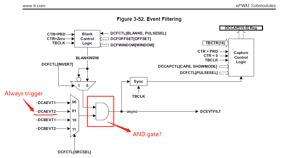
Hello,
(1)As shown in the figure, is it AND gate?
If it is an AND gate, then the schematic in the manual, Offset(n) is low, Window(n) is high. If Blanking window not inverted and DCAEVT2 is always high, then the true blanking time is the offset time. But the result of the TI routine is the opposite.
(\controlSUITE\device_support\f2806x\v151\F2806x_examples_ccsv5\epwm_blanking_window)

(2)DCOFFSET cannot be set to 0 when CBC?
TBPRD = 1000;
CTRMODE = TB_COUNT_UP;
PWM1A = AQ_CLEAR;
DCFWINDOW = 250;
DCFCTL.bit.PULSESEL = DC_PULSESEL_ZERO;
BLANKINV = DC_BLANK_NOTINV;

The DCAEVT2 event is always triggered.

DCAEVT2 --> Blanking Window --> DCEVTFILT --> DCAEVT2.force --> Cycle-by-Cycle(CBC)Trip Events --> PWM1A=TZ_FORCE_HI.

If I set DCOFFSET to 0, PWM1A will always high, and the Blanking window does not work at all.
If I set DCOFFSET to be less than or equal to 998,and The blanking window works properly. In the blanking window time, PWM1A is low and other locations are high.

Why can't I set the offset to 0 at the beginning of each cycle, let the blanking window work from 0?

Best regards.

  • Have someone can help me to solve this question?pls~~
  • Yong,
    I can see why this is confusing. The diagram does not indicate if the "BLANKWDW" line is active high or active low. Reading the text of the chapter and hearing what you have said I assume that the BLANKWDW line goes low during a blanking window. (I couldn't find any statement that said it was active high)

    I guess there is a chance that the inverting bubble on the inverting mux could be drawn in the wrong location, but these are small details and in both cases the diagram represents the function of the module.

    Regards,
    Cody
  • Dear Cody,
    Thanks for your reply.I understand what you mean.
    It is “Figure 3-53. Blanking Window Timing Diagram” that made me misunderstood.
    The second question. These days, I tried different combinations of the four variable values.(BLANKINV, PULSESEL, DCFOFFSET, DCFWINDOW)
    Test results let me confusing. Sometimes it seems that there is a 3 cycle delay from Offset(n) to Window(n).However, when Blanking window inverted, when some values are selected, some experimental results seem to overturn this conclusion.I feel like there is a bug in the boundary position.I hope you have more internal details to help me use this module reliably.
    Regards.

  • Yong,

    what do you mean by the following quote?

    Yong Meng said:
    there is a 3 cycle delay from Offset(n) to Window(n).

    How can you tell there is a delay between Offset and Window? Maybe drawing a diagram could help you explain it.

    Regards,
    Cody 

  • Dear Cody,
    The main parameters of PWM are as follows:

    EPwm1Regs.TBPRD = 1000;
    EPwm1Regs.TBCTL.bit.CTRMODE = TB_COUNT_UP;
    EPwm1Regs.AQCTLA.bit.CAU = AQ_CLEAR;         -----> PWM1A is always low
    EPwm1Regs.AQCTLB.bit.ZRO = AQ_TOGGLE;      -----> PWM1B is TOGGLE at CTR=0

    EPwm1Regs.TZSEL.bit.DCAEVT2 = 1;                  -----> Enable DCBEVT2 as a CBC trip source
    EPwm1Regs.TZCTL.bit.TZA = TZ_FORCE_HI;    -----> CBC trip = Force EPWM1A to a high state
    EPwm1Regs.TZCTL.bit.TZB = TZ_NO_CHANGE;

    EPwm1Regs.DCFCTL.bit.SRCSEL = DC_SRC_DCAEVT2;
    EPwm1Regs.DCFCTL.bit.BLANKINV = DC_BLANK_NOTINV;
    EPwm1Regs.DCFCTL.bit.PULSESEL = DC_PULSESEL_ZERO;

    EPwm1Regs.DCCAPCTL.bit.CAPE = 1;

    The DCAEVT2 event is always triggered.

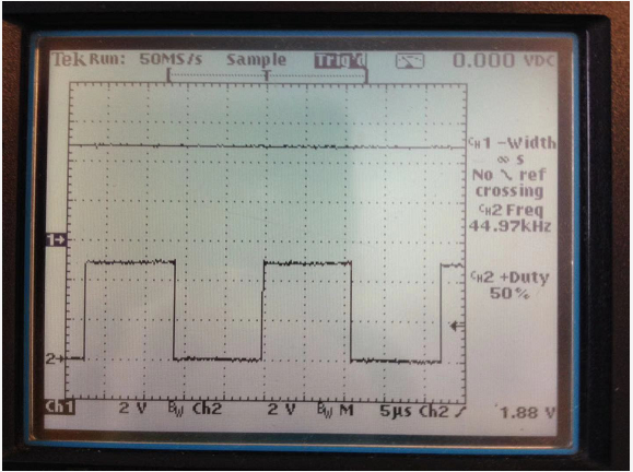
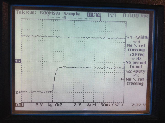
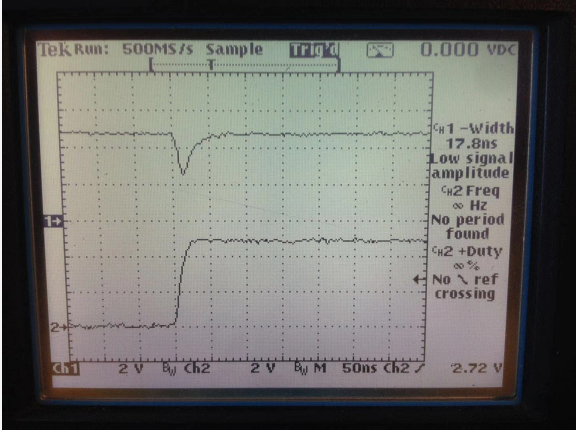
    In the figure, CH1 is PWM1A, CH2 is PWM1B.
    When "EPwm1Regs.DCFOFFSET=998" and "EPwm1Regs.DCFWINDOW=250" results as shown
    EPwm1Regs.DCCAP=250

    When "EPwm1Regs.DCFOFFSET=999" and "EPwm1Regs.DCFWINDOW=250" results as shown
    EPwm1Regs.DCCAP=251

    When "EPwm1Regs.DCFOFFSET=0" and "EPwm1Regs.DCFWINDOW=250" results as shown
    EPwm1Regs.DCCAP=1


    Only the delay of 3 cycles can explain why the blanking window of Figure 2 and Figure 3 does not work.

    In Figure 2, although the blanking window does not work, the capture value is 251.If according to the result of PWM1A, then DCCAP should be 0 or 1.

    I think there are bugs after the blanking window offset ends and after the blanking window ends.
    In these key positions, you may need to pay attention to some details when using it. For example, what happens when the Trip is always triggered, what happens when the blanking window offset is set to 0, and what happens when the blanking window is set to 0.
    Regards.
  • Let Cycle-by-Cycle (CBC)Trip Events be set to Disable, Then use DCAEVT2 to control PWM1A.

    EPwm1Regs.TBPRD = 1000;
    EPwm1Regs.TBCTL.bit.CTRMODE = TB_COUNT_UP;
    EPwm1Regs.AQCTLA.bit.CAU = AQ_CLEAR;         -----> PWM1A is always low
    EPwm1Regs.AQCTLB.bit.ZRO = AQ_TOGGLE;      -----> PWM1B is TOGGLE at CTR=0

    EPwm1Regs.TZCTL.bit.DCAEVT2 = 1;  -----> Digital Compare Output A Event 2 Action = Force EPWM1A to a high state

    EPwm1Regs.DCFCTL.bit.SRCSEL = DC_SRC_DCAEVT2;
    EPwm1Regs.DCFCTL.bit.BLANKINV = DC_BLANK_NOTINV;
    EPwm1Regs.DCFCTL.bit.PULSESEL = DC_PULSESEL_ZERO;

    EPwm1Regs.DCCAPCTL.bit.CAPE = 1;

    The DCAEVT2 event is always triggered.

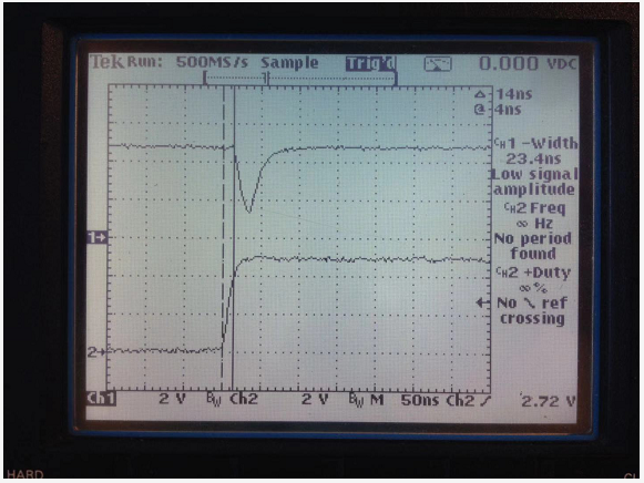
    In the figure, CH1 is PWM1A, CH2 is PWM1B.
    When "EPwm1Regs.DCFOFFSET=0" and "EPwm1Regs.DCFWINDOW=250" results as shown
    EPwm1Regs.DCCAP=1

    Zoom in on the trigger position, as shown

    Look at Figure 2, There is no delay between Offset and Window. PWM1A goes low at CTR=ZERO.

    So the above conclusion is not true here. The results of the experiment are contradictory and cannot be explained.

  • When the blanking window is inverted.

    EPwm1Regs.TBPRD = 1000;
    EPwm1Regs.TBCTL.bit.CTRMODE = TB_COUNT_UP;
    EPwm1Regs.AQCTLA.bit.CAU = AQ_CLEAR;         -----> PWM1A is always low
    EPwm1Regs.AQCTLB.bit.ZRO = AQ_TOGGLE;      -----> PWM1B is TOGGLE at CTR=0

    EPwm1Regs.TZSEL.bit.DCAEVT2 = 1;                  -----> Enable DCBEVT2 as a CBC trip source
    EPwm1Regs.TZCTL.bit.TZA = TZ_FORCE_HI;    -----> CBC trip = Force EPWM1A to a high state
    EPwm1Regs.TZCTL.bit.TZB = TZ_NO_CHANGE;

    EPwm1Regs.DCFCTL.bit.SRCSEL = DC_SRC_DCAEVT2;
    EPwm1Regs.DCFCTL.bit.BLANKINV = DC_BLANK_INV;  -----> Blanking window inverted
    EPwm1Regs.DCFCTL.bit.PULSESEL = DC_PULSESEL_ZERO;

    EPwm1Regs.DCCAPCTL.bit.CAPE = 1;

    The DCAEVT2 event is always triggered.

    In the figure, CH1 is PWM1A, CH2 is PWM1B.
    When "EPwm1Regs.DCFOFFSET=0" and "EPwm1Regs.DCFWINDOW=1" results as shown
    EPwm1Regs.DCCAP=3


    When "EPwm1Regs.DCFOFFSET=0" and "EPwm1Regs.DCFWINDOW=2" results as shown
    EPwm1Regs.DCCAP=3

    When "EPwm1Regs.DCFOFFSET=0" and "EPwm1Regs.DCFWINDOW=3" results as shown
    EPwm1Regs.DCCAP=3

    When "EPwm1Regs.DCFOFFSET=1" and "EPwm1Regs.DCFWINDOW=1" results as shown
    EPwm1Regs.DCCAP=4

    When "EPwm1Regs.DCFOFFSET=1" and "EPwm1Regs.DCFWINDOW=2" results as shown
    EPwm1Regs.DCCAP=4

    When "EPwm1Regs.DCFOFFSET=1" and "EPwm1Regs.DCFWINDOW=3" results as shown
    EPwm1Regs.DCCAP=4

    Figure 1,Figure 2,Figure 4,Figure 5 isconfused

    The contents of the manual are not sufficient to explain the results of the experiment.

  • Great, thanks for the detailed report!

    Could you share a simple .out file that shows the error in each case? It will be hugely helpful. I also agree the documentation does not provide enough information to explain this phenomenon.


    Thanks,
    Cody 

  • Dear Cody,
    No problem. I can send you the complete project for easier testing. I want to send a private message to you on TI E2E, but I can't find you in the recipient. Can you tell me your email?
    Thanks.

  • Dear Cody,
    Thanks for your reply. I have packaged the project and document for you. I send a private message to you on TI E2E. It is in the attachment, can you receive it? (Blanking package.rar)
    Regards.

  • Yong,
    I have received it, thanks. I will reply to you here after I look at the files.

    Regards,
    Cody
  • Yong,

    First I should say that typically the TZ are used as a reaction to something in they system, not normally always left triggered. But for your experiments, I see why you did this.

    I believe that this stems from an Errata that can be found linked below. The errata states that there is a small window around  the end of a blanking window where TZ events should not occur. I think this errata may need to be updated to also include a severl cycle window around the end of the DCFOFFSET.

    Now I saw 3 major posts with different results, I will try to summarize my initial thoughts on each of those below.( If I understood anything incorrectly, please let me know)

    1. This post shows the DC event working correctly, then in the later captures shows PWMa always remaining high.
      1. DCFOFFSET =998 resulting in DCCAP =250, this shows that a trip event working correctly.
      2. DCFOFFSET = 999 Resulting in DCCAP=251, this shows that a ACTLA.CAU event was ignored(or overwritten) within 3 cycles of the DCFOFFSET ending
      3. DCFOFFSET = 0 Resulting in DCCAP=251, this is similar to b above.
    2. This post highlights that it is the Trip-Zone(TZ) TZA logic that is ultimately causing this in inadvertent trigger not the DCAEVT2 logic.
      1. I believe that this is a race condition. Theory: It seems to be logical that the DCAEVT2 trip would work slightly slower than the TZA event being triggered by the DCAEVT2. There is simply more logic for the signal to propagate through. Thus the faster signal happens before the CAU event and we see no problems while the slower signal will come after the CAU event and overwrites it to a logic high.
    3. This post shows glitching that occurs when an event occurs within 3 cycles of the DCFWINDOW ending
    4. I think this behavior is described in an errata "ePWM: An ePWM Glitch can Occur if a Trip Remains Active at the End of the Blanking Window" which can be found in SPRZ342n.pdf.

    Thanks for your detailed dive into this problem!
    Cody 

  • Dear Cody,
    Because TZ1 is easier to trigger DCAEVT2. In real applications, I will use an internal comparator instead of TZ1.

    Thanks for your reminder, it seems that I downloaded the Errata is old.
    I downloaded SPRZ342M.pdf in October, It didn't write about the Blanking window. Obviously the errata of the blanking window has been included in the SPRZ342N.pdf

    c.DCFOFFSET = 0 Resulting in DCCAP=251, this is similar to b above.
    --------The above post is incorrect, should be DCFOFFSET=0 Resulting in DCCAP=1.(DCFWINDOW=250)

    The phenomenon in the errata refers to the end of the blanking window. The current problem should occur after the end of the DCFOFFSET.

    I agree with you that this is a racing condition. 


    Regards.

  • Yong,
    if it is OK with you I will close this thread and close this issue offline.

    Regards,
    Cody
  • Dear Cody,

    I wish you a happy New Year.
    OK, You can close this thread and hope that the errata can be updated soon.

    Regards.