Recently we have met some issue during our software development when using F28377SPZPS chip on our own board. The issue is that when we do the ADC sampling, there is always noise in the signal that we sampled.
We observed the same noise on LAUNCHXL-F28379D by using both example code(adc_soc_epwm_cpu01) and our own code. We are not quite sure this is a hardware issue.
Here is how we notice this issue and how we trying to solve:
- The first time we notice this noise is when we do the control, the current always has some unknown peak, we thought it is the control issue, but finally turns out that the current we sampled has random noise;
- When we debug, first we checked the hardware input and reference 3.3V signal. All the signal is clean. Also, we eliminated the possibility that ground causes this;
- Then we checked the ADC configuration, we thought it may be caused by the clock configuration or S/H window is too small. Then we lower the clock rate(PRESCALE = 6) and enlarge the ACQPS register (set to 50), it doesn’t help;
- We try to use the example code that from TI to test on our board, the issue remains;
- We try both example code and our own code on LANCHPAD, the issue remains(but the ADC count spike is smaller than 28377S);
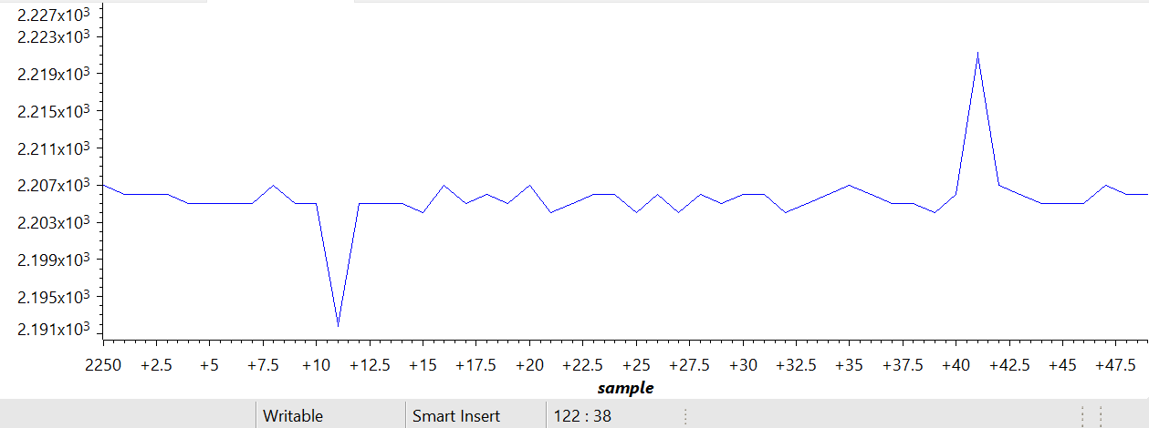
Below is the ADC register value that we recorded on LANCHPAD, the ADC input is using a 1.65V voltage generated by 3.3V on board, the noise is totally random: