This thread has been locked.

If you have a related question, please click the "Ask a related question" button in the top right corner. The newly created question will be automatically linked to this question.

CCS/2MTR-DYNO: Issues with Lab 6E in code composer

Part Number: 2MTR-DYNO
Other Parts Discussed in Thread: BOOSTXL-DRV8301, , MOTORWARE

Tool/software: Code Composer Studio

Dear all,

For my graduation project, I am looking into regenerative braking.

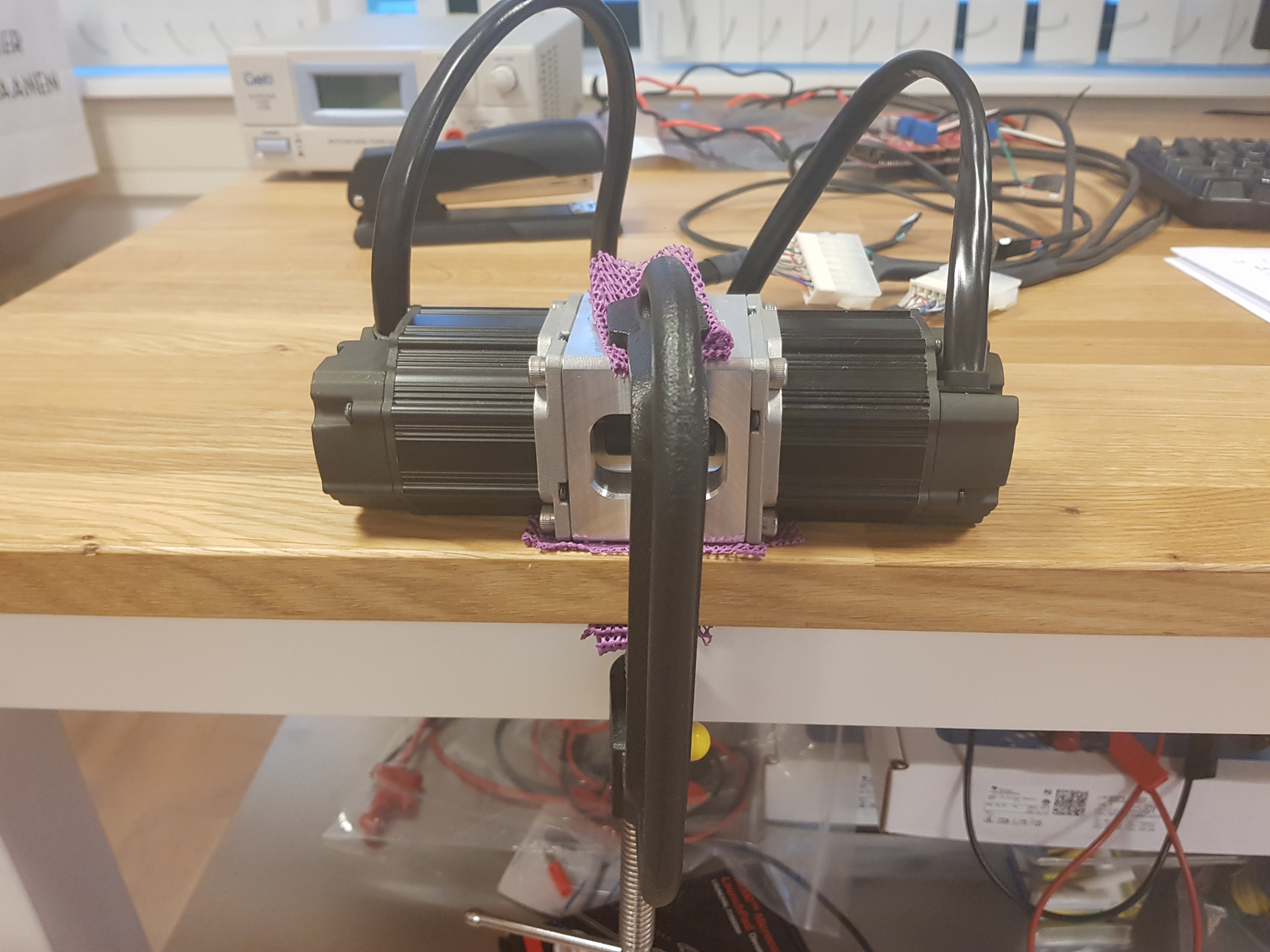
From previous graduates, I have learned that it is possible to investigate this with the 2MTR-DYNO InstaSPIN-FOC Evaluation Module together with a F28096M and 2x BoostXL-DRV8301.

The problem that I currently have is the following: 

- I can get code composer to run and the previous intern used lab 6e to run his experiments.

- I can get one engine to run, change rpm, and change acceleration on the shaft ( .speedref_krpm and .maxaccel.krpmps )

- the power source I use is 24 V

For a variety of different RPM I want the second electric engine to run as a generator while using different amounts of amperes.

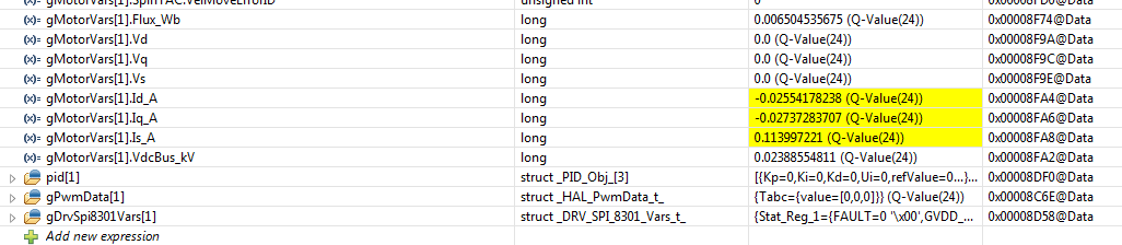
While in code composer I have to idea how to change the amperes given to the system.  

I tried changing the amperes in Motor Vars > Crtl version but with no succes ( ID_ref_A)

And when I try to start the second engine, gMotorVars[1].flag_run_identity and changing that value from o to 1 it makes a loud sound.

I know I must be doing something extremely wrong, The problem being I am an aeronautical engineering student with no experience in programming, so hopefully one of you can explain to me how to keep going.

Thank you all for your time.

Kind regards,

Robert

Excuse me if I have put this one in the wrong threat, It is my first time on the forum

  • Hi Robert

    Have you had a chance to review any of the documentation in Motorware? I understand you have a specific end goal in mind, but would encourage you to explore the other labs that will help to lay a foundation for evaluation of the code. Some of the questions you have, such as how to command a torque/current reference, are answered during the review of the lab guide. I would recommend you start with going through some of the Motorware labs, such as 2b, 4, 5b, and 7, to get a better understanding of the code and InstaSPIN in general. The write-up for 11d goes into detail for controlling 2 motors, which should help your goal

    Please take some time to go over the lab guide. If you continue to have issues or questions, please feel free to continue on this thread

    Sean
  •  Hi Sean,

    Firstly massive thanks for the fast reply and I am making steady progress.

    Hopefully you can help me again (lab 4a)

     Set “Flag_enableSys” to true and then set “Flag_Run_Identify” to true.

     Increase the variable “gMotorVars.IqRef_A” until the shaft starts spinning, try increments of 0.1 (Q-Value(24)).

    o Notice that if the IqRef value is not set high enough, the shaft will slowly oscillate. The slow oscillation (1Hz) is due to the forced startup routine which is called “forced angle”. The forced angle allows InstaSPIN to start from zero speed at full motor torque. If the motor shaft is spinning above 1Hz then the forced angle is off and true closed loop control is performed. The forced angle can be manually turned off. One reason to turn off the forced angle is to have smooth transitions through zero speed.

    o Notice that because the control is a torque controller and the motor is unloaded, the shaft will spin to full (voltage limited) speed.

    First bullet point: I assume true means changing the value from 0 to 1

    The problem arrises at the second bullet point I cannot find: gMotorVars.IqRef_A

    It is not within the list of  gMotorVars variables

    I can find it under:

    - crtlversion

    - Vbias

    But not within my gmotorvars values.

    I followed each step within lab 4 but have no clue where I should look else.

    And if i change in in the crtlversion setting nothing happens

  • Yes, the first bullet does refer to setting the value to '1'

    Were you able to import the JavaScript file into the scripting console? That should update the expressions watch window with the pertinent variables for the lab you are working in. To do this, navigate to 'View -> Scripting Console' which should open a new window in your CCS view. The scripting console has a small file icon that you can use to navigate to a file. Navigate to C:\ti\motorware\motorware_1_01_00_18\sw\solutions\instaspin_foc\src, change the file type to JavaScript files, and select proj_lab04.js. This should update the expressions watch window

    Alternatively, you can always add a new variable to the watch window manually by selecting "Add new expression" at the bottom of the watch window and typing in gMotorVars.IqRef_A

    Sean
  • once again Sean, thank you for helping me out ! I will try everything in my power to be quite for some time :)
  • Good afternoon Sean,

    I just have one quick question regarding lab 10D,

    I have worked through all the labs you recommended but have some issues here.

    When I want to drive both motors ( as seen in the included picture) and follow every step the problem i found is the following.

    Both engines are connected on one shaft when I run one engine there is no issue.

    But when I want to run both engine ( second engine with 0.0 speed ref and acceleration ref) the system starts to stutter.

    I stopped the second engine immediately, does this problem occur because they are both on the same shaft ? 

    If i want to run the second engine as a generator ( like mentioned in the first question ) do I have to use lab 6E, because of the problems found with this lab ?

    Thanks once again and have a great weekend

    Robert

  • Hello,

    I kept trying to solve the problem but kept finding one,

    As mentioned in Lab 4 you can change the input A with gMotorVars.IqRef_A.

    But if I run lab 6E for example there is no gmotorvars.IqRef_A. It was under gmotorvars > CrtlVersion but this is completely gone.

    only Gmotorvars.Iq_A is available.

    If i change Iq_ref_A in lab 10d nothing happens... what am I doing worng ?

    I am completely stuck again so any form of help will be greatly appreciated.

    Robert

  • Robert

    Lab10d is a now deprecated lab, we instead recommend lab11d for dual motor control. Can you please have a try of that lab and report back on your progress? Sorry for the inconvenience

    Sean
  • Sean,

    Thanks again for the help. Sorry, I am in the Netherlands therefor I cannot try it right now but will do tomorrow morning.
    Still I am wondering could you explain me why gmotorvars is gone ? Since I followed each step and it doesnt show up anymore?
    The other question is, if I change IdRef_A or IqRef_A nothing happens, it there a reason why ?
    Sorry for all the questions but nobody can help me and my graduation deadline is at the end of January.

    Cheers and thank you

    Robert
  • Lab10d uses 2 instances of gMotorVars, one for each motor being controlled. You won't be able to add a watch window expression without adding the array index after it, like: gMotorVars[0].IqRef_A

    Also, lab10d is velocity control. Setting an Iq reference doesn't make sense in this context, as the speed PI controller is in turn controlling the Iq and Id PI controller references. You'll want to set gMotorVars[0].SpeedRef_krpm

    Sean
  • So that is most likely the reason, if both engines are on the same shaft and you change speedref_krpm of both engines the system will stutter since they are driving in the opposite direction?
    So if I understand correctly tomorrow for me:
    Try lab 11d for dual motor control ? is this also the lab where I can set one motor as a generator ? of is lab 6E preferred ?

    Sean thanks once again

    Robert

  • Dear Sean,

    I have looked into lab 11D for dual motor control. And I am able to controll both motors .
    When I set engine 0 to: identity true, 0 speedref and 0 acceleration nothing happens ( as expected.)
    When I set engine 1 to: identity true, 1 krpm and 0.5 acceleration innitially it sounds like it is working ( engine 0 is working as a load/generator engine 1 is the motor).
    But after 2 seconds the system starts to stutter and makes a weird sound. ( i did shut down engine 1 immediately after though)
    So I am still not able to use one engine as a generator and one as a motor. Combined with the fact that I have no idea how to change the amps used by the motor or generated by the generator.

    Thanks once again
    Robert

  • This is not a use case we've encountered before for the dual motor lab, so bear with me

    The two motors you are using are connected to the same DC bus? Have you taken care to limit the speed to prevent DC bus pumping that can damage the circuitry?

    You will need to command an Id reference, and it will need to be tuned to properly limit the generator action back into the system. I'm not sure you need to set the Flag_Run_Identify to true, as it will enable the PWM output and try to drive the motor. Perhaps your second machine is acting as a motor trying to regulate to 0 speed instead of acting like a generator? You may want to check the PWM output to make sure it's disabled when you should be generating

    Sean
  • Sean,

    I hope to clarify my test setup a little bit

    These are the two DC motors connected to one shaft. Each motor is connected to a motor controller and  both motor controllers are connected to one launchpad.

    With lab 11d,as you adviced I want to use the left engine as engine and the right engine as generator.

    So if I understand corretly I have to check the PWM output to make it work as a generator ?

    Thanks once again.

    Robert

  • I'm more asking that you check the device peripherals for sanity checks of your system. If the PWM is driving an output, you can assume that the machine downstream is being used as a motor/load and not a generator.

    Sean
  • excuse me sean but what does "PWM driving an output" mean ?
  • Your switches (I.e. MOSFET or IGBT) are having their gates "driven" by the PWM outputs to induce inversion in the FET. If you are driving the FETs, you are conducting power to the motor

    Sean
  • Hi Robert

    If there are no more questions, I will close this thread for now

    Sean