


Other Parts Discussed in Thread: DRV8301, MOTORWARE
Tool/software: Code Composer Studio
Hello, I am currently running a BLDC motor using the LAUNCHXL-F28069M launchpad and DRV8301 booster pack.
I am running lab5b from motorware with a TI motor (DT4260-24-055-04), the motor parameters are below;
The motor runs at the goal speed of 5000 RPM with no load, however the response is not as smooth as I would like. The steady state error of the motor speed is around 4.8% and I would like to get below 1%.
I have also updated the I and V bias values according to lab 3I have undertaken Lab 2 to identify the motor parameters and updated these values in the user.h file.
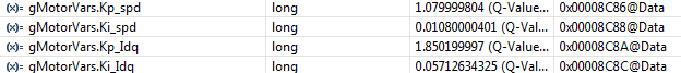
My Kp_I and Ki_I gains were calculated according to Lab 5b;
and Kp_s and Ki_s gains were changed using a trial and error method to find the lowest steady state error on the speed response.
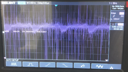
These are my output current waveforms which are incredibly noisy and not smooth so I think these might be the cause of the motor variance.
Phase A
Phase B

Phase C

How do I fix this issue? Are my parameter values in user.h causing the random current waveforms? Thankyou for any help in advance.
this is the user_j1.h file
#ifndef _USER_J1_H_
#define _USER_J1_H_
/* --COPYRIGHT--,BSD
 * Copyright (c) 2012, Texas Instruments Incorporated
 * All rights reserved.
 *
 * Redistribution and use in source and binary forms, with or without
 * modification, are permitted provided that the following conditions
 * are met:
 *
 * *  Redistributions of source code must retain the above copyright
 *    notice, this list of conditions and the following disclaimer.
 *
 * *  Redistributions in binary form must reproduce the above copyright
 *    notice, this list of conditions and the following disclaimer in the
 *    documentation and/or other materials provided with the distribution.
 *
 * *  Neither the name of Texas Instruments Incorporated nor the names of
 *    its contributors may be used to endorse or promote products derived
 *    from this software without specific prior written permission.
 *
 * THIS SOFTWARE IS PROVIDED BY THE COPYRIGHT HOLDERS AND CONTRIBUTORS "AS IS"
 * AND ANY EXPRESS OR IMPLIED WARRANTIES, INCLUDING, BUT NOT LIMITED TO,
 * THE IMPLIED WARRANTIES OF MERCHANTABILITY AND FITNESS FOR A PARTICULAR
 * PURPOSE ARE DISCLAIMED. IN NO EVENT SHALL THE COPYRIGHT OWNER OR
 * CONTRIBUTORS BE LIABLE FOR ANY DIRECT, INDIRECT, INCIDENTAL, SPECIAL,
 * EXEMPLARY, OR CONSEQUENTIAL DAMAGES (INCLUDING, BUT NOT LIMITED TO,
 * PROCUREMENT OF SUBSTITUTE GOODS OR SERVICES; LOSS OF USE, DATA, OR PROFITS;
 * OR BUSINESS INTERRUPTION) HOWEVER CAUSED AND ON ANY THEORY OF LIABILITY,
 * WHETHER IN CONTRACT, STRICT LIABILITY, OR TORT (INCLUDING NEGLIGENCE OR
 * OTHERWISE) ARISING IN ANY WAY OUT OF THE USE OF THIS SOFTWARE,
 * EVEN IF ADVISED OF THE POSSIBILITY OF SUCH DAMAGE.
 * --/COPYRIGHT--*/

//! \file   solutions/instaspin_foc/boards/boostxldrv8301_revB/f28x/f2806xF/src/user_j1.h
//! \brief Contains the public interface for user initialization data for the CTRL, HAL, and EST modules
//!
//! (C) Copyright 2012, Texas Instruments, Inc.


// **************************************************************************
// the includes

//!
//!
//! \defgroup USER USER
//!
//@{


#ifdef __cplusplus
extern "C" {
#endif

// **************************************************************************
// the defines

//! \brief CURRENTS AND VOLTAGES
// **************************************************************************
//! \brief Defines the full scale frequency for IQ variable, Hz
//! \brief All frequencies are converted into (pu) based on the ratio to this value
//! \brief this value MUST be larger than the maximum speed that you are expecting from the motor
#define USER_IQ_FULL_SCALE_FREQ_Hz        (360)   // 800 Example with buffer for 8-pole 6 KRPM motor to be run to 10 KRPM with field weakening; Hz =(RPM * Poles) / 120

//! \brief Defines full scale value for the IQ30 variable of Voltage inside the system
//! \brief All voltages are converted into (pu) based on the ratio to this value
//! \brief WARNING: this value MUST meet the following condition: USER_IQ_FULL_SCALE_VOLTAGE_V > 0.5 * USER_MOTOR_MAX_CURRENT * USER_MOTOR_Ls_d * USER_VOLTAGE_FILTER_POLE_rps,
//! \brief WARNING: otherwise the value can saturate and roll-over, causing an inaccurate value
//! \brief WARNING: this value is OFTEN greater than the maximum measured ADC value, especially with high Bemf motors operating at higher than rated speeds
//! \brief WARNING: if you know the value of your Bemf constant, and you know you are operating at a multiple speed due to field weakening, be sure to set this value higher than the expected Bemf voltage
//! \brief It is recommended to start with a value ~3x greater than the USER_ADC_FULL_SCALE_VOLTAGE_V and increase to 4-5x if scenarios where a Bemf calculation may exceed these limits
//! \brief This value is also used to calculate the minimum flux value: USER_IQ_FULL_SCALE_VOLTAGE_V/USER_EST_FREQ_Hz/0.7
#define USER_IQ_FULL_SCALE_VOLTAGE_V      (24.0)   // 24.0 Example for boostxldrv8301_revB typical usage and the Anaheim motor

//! \brief Defines the maximum voltage at the input to the AD converter
//! \brief The value that will be represented by the maximum ADC input (3.3V) and conversion (0FFFh)
//! \brief Hardware dependent, this should be based on the voltage sensing and scaling to the ADC input
#define USER_ADC_FULL_SCALE_VOLTAGE_V       (26.314)      // 26.314 boostxldrv8301_revB voltage scaling

//! \brief Defines the full scale current for the IQ variables, A
//! \brief All currents are converted into (pu) based on the ratio to this value
//! \brief WARNING: this value MUST be larger than the maximum current readings that you are expecting from the motor or the reading will roll over to 0, creating a control issue
#define USER_IQ_FULL_SCALE_CURRENT_A         (20.0) // 20.0 Example for boostxldrv8301_revB typical usage

//! \brief Defines the maximum current at the AD converter
//! \brief The value that will be represented by the maximum ADC input (3.3V) and conversion (0FFFh)
//! \brief Hardware dependent, this should be based on the current sensing and scaling to the ADC input
#define USER_ADC_FULL_SCALE_CURRENT_A        (33.0)  // 33.0 boostxldrv8301_revB current scaling

//! \brief Defines the number of current sensors used
//! \brief Defined by the hardware capability present
//! \brief May be (2) or (3)
#define USER_NUM_CURRENT_SENSORS            (3)   // 3 Preferred setting for best performance across full speed range, allows for 100% duty cycle

//! \brief Defines the number of voltage (phase) sensors
//! \brief Must be (3)
#define USER_NUM_VOLTAGE_SENSORS            (3) // 3 Required

//! \brief ADC current offsets for A, B, and C phases
//! \brief One-time hardware dependent, though the calibration can be done at run-time as well
//! \brief After initial board calibration these values should be updated for your specific hardware so they are available after compile in the binary to be loaded to the controller
#define   I_A_offset    (0.8301919103)
#define   I_B_offset    (0.8294886947)
#define   I_C_offset    (0.8251147866)

//! \brief ADC voltage offsets for A, B, and C phases
//! \brief One-time hardware dependent, though the calibration can be done at run-time as well
//! \brief After initial board calibration these values should be updated for your specific hardware so they are available after compile in the binary to be loaded to the controller
#define   V_A_offset    (0.4947562814)
#define   V_B_offset    (0.5046098232)
#define   V_C_offset    (0.4961007833)


//! \brief CLOCKS & TIMERS
// **************************************************************************
//! \brief Defines the Pulse Width Modulation (PWM) frequency, kHz
//! \brief PWM frequency can be set directly here up to 30 KHz safely (60 KHz MAX in some cases)
//! \brief For higher PWM frequencies (60 KHz+ typical for low inductance, high current ripple motors) it is recommended to use the ePWM hardware
//! \brief and adjustable ADC SOC to decimate the ADC conversion done interrupt to the control system, or to use the software Que example.
//! \brief Otherwise you risk missing interrupts and disrupting the timing of the control state machine
#define USER_PWM_FREQ_kHz                (30.0) //30.0 Example, 8.0 - 30.0 KHz typical; 45-80 KHz may be required for very low inductance, high speed motors

//! \brief Defines the maximum Voltage vector (Vs) magnitude allowed.  This value sets the maximum magnitude for the output of the
//! \brief Id and Iq PI current controllers.  The Id and Iq current controller outputs are Vd and Vq.
//! \brief The relationship between Vs, Vd, and Vq is:  Vs = sqrt(Vd^2 + Vq^2).  In this FOC controller, the
//! \brief Vd value is set equal to USER_MAX_VS_MAG*USER_VD_MAG_FACTOR.  Vq = sqrt(USER_MAX_VS_MAG^2 - Vd^2).
//! \brief Set USER_MAX_VS_MAG = 0.5 for a pure sinewave with a peak at SQRT(3)/2 = 86.6% duty cycle.  No current reconstruction is needed for this scenario.
//! \brief Set USER_MAX_VS_MAG = 1/SQRT(3) = 0.5774 for a pure sinewave with a peak at 100% duty cycle.  Current reconstruction will be needed for this scenario (Lab10a-x).
//! \brief Set USER_MAX_VS_MAG = 2/3 = 0.6666 to create a trapezoidal voltage waveform.  Current reconstruction will be needed for this scenario (Lab10a-x).
//! \brief For space vector over-modulation, see lab 10 for details on system requirements that will allow the SVM generator to go all the way to trapezoidal.
#define USER_MAX_VS_MAG_PU        (0.5)    // Set to 0.5 if a current reconstruction technique is not used.  Look at the module svgen_current in lab10a-x for more info.


//! \brief DECIMATION
// **************************************************************************
//! \brief Defines the number of pwm clock ticks per isr clock tick
//!        Note: Valid values are 1, 2 or 3 only
#define USER_NUM_PWM_TICKS_PER_ISR_TICK        (3)

//! \brief Defines the number of isr ticks (hardware) per controller clock tick (software)
//! \brief Controller clock tick (CTRL) is the main clock used for all timing in the software
//! \brief Typically the PWM Frequency triggers (can be decimated by the ePWM hardware for less overhead) an ADC SOC
//! \brief ADC SOC triggers an ADC Conversion Done
//! \brief ADC Conversion Done triggers ISR
//! \brief This relates the hardware ISR rate to the software controller rate
//! \brief Typcially want to consider some form of decimation (ePWM hardware, CURRENT or EST) over 16KHz ISR to insure interrupt completes and leaves time for background tasks
#define USER_NUM_ISR_TICKS_PER_CTRL_TICK       (1)      // 2 Example, controller clock rate (CTRL) runs at PWM / 2; ex 30 KHz PWM, 15 KHz control

//! \brief Defines the number of controller clock ticks per current controller clock tick
//! \brief Relationship of controller clock rate to current controller (FOC) rate
#define USER_NUM_CTRL_TICKS_PER_CURRENT_TICK   (1)      // 1 Typical, Forward FOC current controller (Iq/Id/IPARK/SVPWM) runs at same rate as CTRL.

//! \brief Defines the number of controller clock ticks per estimator clock tick
//! \brief Relationship of controller clock rate to estimator (FAST) rate
//! \brief Depends on needed dynamic performance, FAST provides very good results as low as 1 KHz while more dynamic or high speed applications may require up to 15 KHz
#define USER_NUM_CTRL_TICKS_PER_EST_TICK       (1)      // 1 Typical, FAST estimator runs at same rate as CTRL;

//! \brief Defines the number of controller clock ticks per speed controller clock tick
//! \brief Relationship of controller clock rate to speed loop rate
#define USER_NUM_CTRL_TICKS_PER_SPEED_TICK  (15)   // 15 Typical to match PWM, ex: 15KHz PWM, controller, and current loop, 1KHz speed loop

//! \brief Defines the number of controller clock ticks per trajectory clock tick
//! \brief Relationship of controller clock rate to trajectory loop rate
//! \brief Typically the same as the speed rate
#define USER_NUM_CTRL_TICKS_PER_TRAJ_TICK   (15)   // 15 Typical to match PWM, ex: 10KHz controller & current loop, 1KHz speed loop, 1 KHz Trajectory


//! \brief LIMITS
// **************************************************************************
//! \brief Defines the maximum negative current to be applied in Id reference
//! \brief Used in field weakening only, this is a safety setting (e.g. to protect against demagnetization)
//! \brief User must also be aware that overall current magnitude [sqrt(Id^2 + Iq^2)] should be kept below any machine design specifications
#define USER_MAX_NEGATIVE_ID_REF_CURRENT_A     (-0.5 * USER_MOTOR_MAX_CURRENT)   // -0.5 * USER_MOTOR_MAX_CURRENT Example, adjust to meet safety needs of your motor

//! \brief Defines the R/L estimation frequency, Hz
//! \brief User higher values for low inductance motors and lower values for higher inductance
//! \brief motors.  The values can range from 100 to 300 Hz.
#define USER_R_OVER_L_EST_FREQ_Hz (300)               // 300 Default

//! \brief Defines the low speed limit for the flux integrator, pu
//! \brief This is the speed range (CW/CCW) at which the ForceAngle object is active, but only if Enabled
//! \brief Outside of this speed - or if Disabled - the ForcAngle will NEVER be active and the angle is provided by FAST only
#define USER_ZEROSPEEDLIMIT   (0.5 / USER_IQ_FULL_SCALE_FREQ_Hz)     // 0.002 pu, 1-5 Hz typical; Hz = USER_ZEROSPEEDLIMIT * USER_IQ_FULL_SCALE_FREQ_Hz

//! \brief Defines the force angle frequency, Hz
//! \brief Frequency of stator vector rotation used by the ForceAngle object
//! \brief Can be positive or negative
#define USER_FORCE_ANGLE_FREQ_Hz   (2.0 * USER_ZEROSPEEDLIMIT * USER_IQ_FULL_SCALE_FREQ_Hz)      // 1.0 Typical force angle start-up speed


//! \brief POLES
// **************************************************************************
//! \brief Defines the analog voltage filter pole location, Hz
//! \brief Must match the hardware filter for Vph
#define USER_VOLTAGE_FILTER_POLE_Hz  (364.682)   // 364.682, value for boostxldrv8301_revB hardware


//! \brief USER MOTOR & ID SETTINGS
// **************************************************************************

//! \brief Define each motor with a unique name and ID number
// BLDC & SMPM motors
#define Estun_EMJ_04APB22           101
#define Anaheim_BLY172S             102
#define Tamagawa_A0100 	            103
#define Teknic_M2310PLN04K          104
#define Drone_A2212_1000KV			105
#define Drone_A2313_960KV			106
#define MY_MOTOR 113
// IPM motors
// If user provides separate Ls-d, Ls-q
// else treat as SPM with user or identified average Ls
#define Belt_Drive_Washer_IPM       201
#define Anaheim_Salient             202

// ACIM motors
#define Marathon_5K33GN2A           301

//! \brief Uncomment the motor which should be included at compile
//! \brief These motor ID settings and motor parameters are then available to be used by the control system
//! \brief Once your ideal settings and parameters are identified update the motor section here so it is available in the binary code
//#define USER_MOTOR Estun_EMJ_04APB22
//#define USER_MOTOR Anaheim_BLY172S
//#define USER_MOTOR Tamagawa_A0100
//#define USER_MOTOR Drone_A2313_960KV
//#define USER_MOTOR Teknic_M2310PLN04K
//#define USER_MOTOR Belt_Drive_Washer_IPM
//#define USER_MOTOR Marathon_5K33GN2A
//#define USER_MOTOR Anaheim_Salient
#define USER_MOTOR MY_MOTOR


#if (USER_MOTOR == Estun_EMJ_04APB22)                  // Name must match the motor #define
#define USER_MOTOR_TYPE                 MOTOR_Type_Pm  // Motor_Type_Pm (All Synchronous: BLDC, PMSM, SMPM, IPM) or Motor_Type_Induction (Asynchronous ACI)
#define USER_MOTOR_NUM_POLE_PAIRS       (4)            // PAIRS, not total poles. Used to calculate user RPM from rotor Hz only
#define USER_MOTOR_Rr                   (NULL)         // Induction motors only, else NULL
#define USER_MOTOR_Rs                   (2.303403)     // Identified phase to neutral resistance in a Y equivalent circuit (Ohms, float)
#define USER_MOTOR_Ls_d                 (0.008464367)  // For PM, Identified average stator inductance  (Henry, float)
#define USER_MOTOR_Ls_q                 (0.008464367)  // For PM, Identified average stator inductance  (Henry, float)
#define USER_MOTOR_RATED_FLUX           (0.38)         // Identified TOTAL flux linkage between the rotor and the stator (V/Hz)
#define USER_MOTOR_MAGNETIZING_CURRENT  (NULL)         // Induction motors only, else NULL
#define USER_MOTOR_RES_EST_CURRENT      (1.0)          // During Motor ID, maximum current (Amperes, float) used for Rs estimation, 10-20% rated current
#define USER_MOTOR_IND_EST_CURRENT      (-1.0)         // During Motor ID, maximum current (negative Amperes, float) used for Ls estimation, use just enough to enable rotation
#define USER_MOTOR_MAX_CURRENT          (3.82)         // CRITICAL: Used during ID and run-time, sets a limit on the maximum current command output of the provided Speed PI Controller to the Iq controller
#define USER_MOTOR_FLUX_EST_FREQ_Hz     (20.0)         // During Motor ID, maximum commanded speed (Hz, float), ~10% rated


#elif (USER_MOTOR == MY_MOTOR)
#define USER_MOTOR_TYPE MOTOR_Type_Pm
#define USER_MOTOR_NUM_POLE_PAIRS (4)
#define USER_MOTOR_Rr (NULL)
#define USER_MOTOR_Rs (0.394680709)
#define USER_MOTOR_Ls_d (0.000690890709)
#define USER_MOTOR_Ls_q (0.000690890709)
#define USER_MOTOR_RATED_FLUX (0.0339639522)
#define USER_MOTOR_MAGNETIZING_CURRENT (NULL)
#define USER_MOTOR_RES_EST_CURRENT (1)
#define USER_MOTOR_IND_EST_CURRENT (-1)
#define USER_MOTOR_MAX_CURRENT (3.0)
#define USER_MOTOR_FLUX_EST_FREQ_Hz     (83.3333)

// 2.2689824853 kp_idq


#elif (USER_MOTOR == Anaheim_BLY172S)
#define USER_MOTOR_TYPE                 MOTOR_Type_Pm
#define USER_MOTOR_NUM_POLE_PAIRS       (4)
#define USER_MOTOR_Rr                   (NULL)
#define USER_MOTOR_Rs                   (0.4110007)
#define USER_MOTOR_Ls_d                 (0.0007092811)
#define USER_MOTOR_Ls_q                 (0.0007092811)
#define USER_MOTOR_RATED_FLUX           (0.03279636)
#define USER_MOTOR_MAGNETIZING_CURRENT  (NULL)
#define USER_MOTOR_RES_EST_CURRENT      (1.0)
#define USER_MOTOR_IND_EST_CURRENT      (-1.0)
#define USER_MOTOR_MAX_CURRENT          (5.0)
#define USER_MOTOR_FLUX_EST_FREQ_Hz     (20.0)
#define IPD_HFI_EXC_FREQ_HZ             (750.0)       // excitation frequency, Hz
#define IPD_HFI_LP_SPD_FILT_HZ          (35.0)        // lowpass filter cutoff frequency, Hz
#define IPD_HFI_HP_IQ_FILT_HZ           (100.0)       // highpass filter cutoff frequency, Hz
#define IPD_HFI_KSPD                    (15.0)       // the speed gain value
#define IPD_HFI_EXC_MAG_COARSE_PU       (0.13)         // coarse IPD excitation magnitude, pu
#define IPD_HFI_EXC_MAG_FINE_PU         (0.12)         // fine IPD excitation magnitude, pu
#define IPD_HFI_EXC_TIME_COARSE_S       (0.5)         // coarse wait time, sec max 0.64
#define IPD_HFI_EXC_TIME_FINE_S         (0.5)         // fine wait time, sec max 0.4
#define AFSEL_FREQ_HIGH_PU              (_IQ(15.0 / USER_IQ_FULL_SCALE_FREQ_Hz))
#define AFSEL_FREQ_LOW_PU               (_IQ(10.0 / USER_IQ_FULL_SCALE_FREQ_Hz))
#define AFSEL_IQ_SLOPE_EST              (_IQ((float)(1.0/0.1/USER_ISR_FREQ_Hz)))
#define AFSEL_IQ_SLOPE_HFI              (_IQ((float)(1.0/10.0/USER_ISR_FREQ_Hz)))
#define AFSEL_IQ_SLOPE_THROTTLE_DWN     (_IQ((float)(1.0/0.05/USER_ISR_FREQ_Hz)))
#define AFSEL_MAX_IQ_REF_EST            (_IQ(0.6))
#define AFSEL_MAX_IQ_REF_HFI            (_IQ(0.6))

#define USER_MOTOR_FREQ_LOW				(10.0)			// Hz - suggested to set to 10% of rated motor frequency
#define USER_MOTOR_FREQ_HIGH			(100.0)			// Hz - suggested to set to 100% of rated motor frequency
#define USER_MOTOR_FREQ_MAX				(120.0)			// Hz - suggested to set to 120% of rated motor frequency
#define USER_MOTOR_VOLT_MIN				(3.0)			// Volt - suggested to set to 15% of rated motor voltage
#define USER_MOTOR_VOLT_MAX				(18.0)			// Volt - suggested to set to 100% of rated motor voltage

#elif (USER_MOTOR == Tamagawa_A0100)
#define USER_MOTOR_TYPE                 MOTOR_Type_Pm
#define USER_MOTOR_NUM_POLE_PAIRS       (4)
#define USER_MOTOR_Rr                   (NULL)
#define USER_MOTOR_Rs                   (0.262230158)
#define USER_MOTOR_Ls_d                 (0.000459346687)
#define USER_MOTOR_Ls_q                 (0.000459346687)
#define USER_MOTOR_RATED_FLUX           (0.0484918393)
#define USER_MOTOR_MAGNETIZING_CURRENT  (NULL)
#define USER_MOTOR_RES_EST_CURRENT      (1.0)
#define USER_MOTOR_IND_EST_CURRENT      (-1.0)
#define USER_MOTOR_MAX_CURRENT          (5.0)
#define USER_MOTOR_FLUX_EST_FREQ_Hz     (20.0)
#define IPD_HFI_EXC_FREQ_HZ             (750.0)       // excitation frequency, Hz
#define IPD_HFI_LP_SPD_FILT_HZ          (35.0)        // lowpass filter cutoff frequency, Hz
#define IPD_HFI_HP_IQ_FILT_HZ           (100.0)       // highpass filter cutoff frequency, Hz
#define IPD_HFI_KSPD                    (15.0)       // the speed gain value
#define IPD_HFI_EXC_MAG_COARSE_PU       (0.13)         // coarse IPD excitation magnitude, pu
#define IPD_HFI_EXC_MAG_FINE_PU         (0.12)         // fine IPD excitation magnitude, pu
#define IPD_HFI_EXC_TIME_COARSE_S       (0.5)         // coarse wait time, sec max 0.64
#define IPD_HFI_EXC_TIME_FINE_S         (0.5)         // fine wait time, sec max 0.4
#define AFSEL_FREQ_HIGH_PU              (_IQ(15.0 / USER_IQ_FULL_SCALE_FREQ_Hz))
#define AFSEL_FREQ_LOW_PU               (_IQ(10.0 / USER_IQ_FULL_SCALE_FREQ_Hz))
#define AFSEL_IQ_SLOPE_EST              (_IQ((float)(1.0/0.1/USER_ISR_FREQ_Hz)))
#define AFSEL_IQ_SLOPE_HFI              (_IQ((float)(1.0/10.0/USER_ISR_FREQ_Hz)))
#define AFSEL_IQ_SLOPE_THROTTLE_DWN     (_IQ((float)(1.0/0.05/USER_ISR_FREQ_Hz)))
#define AFSEL_MAX_IQ_REF_EST            (_IQ(0.6))
#define AFSEL_MAX_IQ_REF_HFI            (_IQ(0.6))

#elif (USER_MOTOR == Drone_A2212_1000KV)
#define USER_MOTOR_TYPE                 MOTOR_Type_Pm
#define USER_MOTOR_NUM_POLE_PAIRS       (4)
#define USER_MOTOR_Rr                   (NULL)
#define USER_MOTOR_Rs                   (0.4110007)
#define USER_MOTOR_Ls_d                 (0.0007092811)
#define USER_MOTOR_Ls_q                 (0.0007092811)
#define USER_MOTOR_RATED_FLUX           (0.03279636)
#define USER_MOTOR_MAGNETIZING_CURRENT  (NULL)
#define USER_MOTOR_RES_EST_CURRENT      (1.0)
#define USER_MOTOR_IND_EST_CURRENT      (-1.0)
#define USER_MOTOR_MAX_CURRENT          (5.0)
#define USER_MOTOR_FLUX_EST_FREQ_Hz     (20.0)
#define IPD_HFI_EXC_FREQ_HZ             (750.0)       // excitation frequency, Hz
#define IPD_HFI_LP_SPD_FILT_HZ          (35.0)        // lowpass filter cutoff frequency, Hz
#define IPD_HFI_HP_IQ_FILT_HZ           (100.0)       // highpass filter cutoff frequency, Hz
#define IPD_HFI_KSPD                    (15.0)       // the speed gain value
#define IPD_HFI_EXC_MAG_COARSE_PU       (0.13)         // coarse IPD excitation magnitude, pu
#define IPD_HFI_EXC_MAG_FINE_PU         (0.12)         // fine IPD excitation magnitude, pu
#define IPD_HFI_EXC_TIME_COARSE_S       (0.5)         // coarse wait time, sec max 0.64
#define IPD_HFI_EXC_TIME_FINE_S         (0.5)         // fine wait time, sec max 0.4
#define AFSEL_FREQ_HIGH_PU              (_IQ(15.0 / USER_IQ_FULL_SCALE_FREQ_Hz))
#define AFSEL_FREQ_LOW_PU               (_IQ(10.0 / USER_IQ_FULL_SCALE_FREQ_Hz))
#define AFSEL_IQ_SLOPE_EST              (_IQ((float)(1.0/0.1/USER_ISR_FREQ_Hz)))
#define AFSEL_IQ_SLOPE_HFI              (_IQ((float)(1.0/10.0/USER_ISR_FREQ_Hz)))
#define AFSEL_IQ_SLOPE_THROTTLE_DWN     (_IQ((float)(1.0/0.05/USER_ISR_FREQ_Hz)))
#define AFSEL_MAX_IQ_REF_EST            (_IQ(0.6))
#define AFSEL_MAX_IQ_REF_HFI            (_IQ(0.6))

#elif (USER_MOTOR == Drone_A2313_960KV)
#define USER_MOTOR_TYPE                 MOTOR_Type_Pm
#define USER_MOTOR_NUM_POLE_PAIRS       (4)
#define USER_MOTOR_Rr                   (NULL)
#define USER_MOTOR_Rs                   (0.4110007)
#define USER_MOTOR_Ls_d                 (0.0007092811)
#define USER_MOTOR_Ls_q                 (0.0007092811)
#define USER_MOTOR_RATED_FLUX           (0.03279636)
#define USER_MOTOR_MAGNETIZING_CURRENT  (NULL)
#define USER_MOTOR_RES_EST_CURRENT      (1.0)
#define USER_MOTOR_IND_EST_CURRENT      (-1.0)
#define USER_MOTOR_MAX_CURRENT          (5.0)
#define USER_MOTOR_FLUX_EST_FREQ_Hz     (20.0)
#define IPD_HFI_EXC_FREQ_HZ             (750.0)       // excitation frequency, Hz
#define IPD_HFI_LP_SPD_FILT_HZ          (35.0)        // lowpass filter cutoff frequency, Hz
#define IPD_HFI_HP_IQ_FILT_HZ           (100.0)       // highpass filter cutoff frequency, Hz
#define IPD_HFI_KSPD                    (15.0)       // the speed gain value
#define IPD_HFI_EXC_MAG_COARSE_PU       (0.13)         // coarse IPD excitation magnitude, pu
#define IPD_HFI_EXC_MAG_FINE_PU         (0.12)         // fine IPD excitation magnitude, pu
#define IPD_HFI_EXC_TIME_COARSE_S       (0.5)         // coarse wait time, sec max 0.64
#define IPD_HFI_EXC_TIME_FINE_S         (0.5)         // fine wait time, sec max 0.4
#define AFSEL_FREQ_HIGH_PU              (_IQ(15.0 / USER_IQ_FULL_SCALE_FREQ_Hz))
#define AFSEL_FREQ_LOW_PU               (_IQ(10.0 / USER_IQ_FULL_SCALE_FREQ_Hz))
#define AFSEL_IQ_SLOPE_EST              (_IQ((float)(1.0/0.1/USER_ISR_FREQ_Hz)))
#define AFSEL_IQ_SLOPE_HFI              (_IQ((float)(1.0/10.0/USER_ISR_FREQ_Hz)))
#define AFSEL_IQ_SLOPE_THROTTLE_DWN     (_IQ((float)(1.0/0.05/USER_ISR_FREQ_Hz)))
#define AFSEL_MAX_IQ_REF_EST            (_IQ(0.6))
#define AFSEL_MAX_IQ_REF_HFI            (_IQ(0.6))

#elif (USER_MOTOR == Anaheim_Salient)                 // When using IPD_HFI, set decimation to 1 and PWM to 15.0 KHz
#define USER_MOTOR_TYPE                 MOTOR_Type_Pm
#define USER_MOTOR_NUM_POLE_PAIRS       (4)
#define USER_MOTOR_Rr                   (NULL)
#define USER_MOTOR_Rs                   (0.1215855)
#define USER_MOTOR_Ls_d                 (0.0002298828)
#define USER_MOTOR_Ls_q                 (0.0002298828)
#define USER_MOTOR_RATED_FLUX           (0.04821308)
#define USER_MOTOR_MAGNETIZING_CURRENT  (NULL)
#define USER_MOTOR_RES_EST_CURRENT      (2.0)         // Enter amperes(float)
#define USER_MOTOR_IND_EST_CURRENT      (-0.5)        // Enter negative amperes(float)
#define USER_MOTOR_MAX_CURRENT          (10.0)
#define USER_MOTOR_FLUX_EST_FREQ_Hz     (20.0)
#define IPD_HFI_EXC_FREQ_HZ             (750.0)       // excitation frequency, Hz
#define IPD_HFI_LP_SPD_FILT_HZ          (35.0)        // lowpass filter cutoff frequency, Hz
#define IPD_HFI_HP_IQ_FILT_HZ           (100.0)       // highpass filter cutoff frequency, Hz
#define IPD_HFI_KSPD                    (15.0)       // the speed gain value
#define IPD_HFI_EXC_MAG_COARSE_PU       (0.13)         // coarse IPD excitation magnitude, pu
#define IPD_HFI_EXC_MAG_FINE_PU         (0.12)         // fine IPD excitation magnitude, pu
#define IPD_HFI_EXC_TIME_COARSE_S       (0.5)         // coarse wait time, sec max 0.64
#define IPD_HFI_EXC_TIME_FINE_S         (0.5)         // fine wait time, sec max 0.4
#define AFSEL_FREQ_HIGH_PU              (_IQ(15.0 / USER_IQ_FULL_SCALE_FREQ_Hz))
#define AFSEL_FREQ_LOW_PU               (_IQ(10.0 / USER_IQ_FULL_SCALE_FREQ_Hz))
#define AFSEL_IQ_SLOPE_EST              (_IQ((float)(1.0/0.1/USER_ISR_FREQ_Hz)))
#define AFSEL_IQ_SLOPE_HFI              (_IQ((float)(1.0/10.0/USER_ISR_FREQ_Hz)))
#define AFSEL_IQ_SLOPE_THROTTLE_DWN     (_IQ((float)(1.0/0.05/USER_ISR_FREQ_Hz)))
#define AFSEL_MAX_IQ_REF_EST            (_IQ(0.6))
#define AFSEL_MAX_IQ_REF_HFI            (_IQ(0.6))

#elif (USER_MOTOR == Teknic_M2310PLN04K)
#define USER_MOTOR_TYPE                 MOTOR_Type_Pm
#define USER_MOTOR_NUM_POLE_PAIRS       (4)
#define USER_MOTOR_Rr                   (NULL)
#define USER_MOTOR_Rs                   (0.3918252)
#define USER_MOTOR_Ls_d                 (0.00023495)
#define USER_MOTOR_Ls_q                 (0.00023495)
#define USER_MOTOR_RATED_FLUX           (0.03955824)
#define USER_MOTOR_MAGNETIZING_CURRENT  (NULL)
#define USER_MOTOR_RES_EST_CURRENT      (1.0)
#define USER_MOTOR_IND_EST_CURRENT      (-0.5)
#define USER_MOTOR_MAX_CURRENT          (7.0)
#define USER_MOTOR_FLUX_EST_FREQ_Hz     (20.0)

#elif (USER_MOTOR == Belt_Drive_Washer_IPM)
#define USER_MOTOR_TYPE                 MOTOR_Type_Pm
#define USER_MOTOR_NUM_POLE_PAIRS       (4)
#define USER_MOTOR_Rr                   (NULL)
#define USER_MOTOR_Rs                   (2.832002)
#define USER_MOTOR_Ls_d                 (0.0115)
#define USER_MOTOR_Ls_q                 (0.0135)
#define USER_MOTOR_RATED_FLUX           (0.5022156)
#define USER_MOTOR_MAGNETIZING_CURRENT  (NULL)
#define USER_MOTOR_RES_EST_CURRENT      (1.0)
#define USER_MOTOR_IND_EST_CURRENT      (-1.0)
#define USER_MOTOR_MAX_CURRENT          (4.0)
#define USER_MOTOR_FLUX_EST_FREQ_Hz     (20.0)

#elif (USER_MOTOR == Marathon_5K33GN2A)                      // Name must match the motor #define
#define USER_MOTOR_TYPE                 MOTOR_Type_Induction // Motor_Type_Pm (All Synchronous: BLDC, PMSM, SMPM, IPM) or Motor_Type_Induction (Asynchronous ACI)
#define USER_MOTOR_NUM_POLE_PAIRS       (2)                  // PAIRS, not total poles. Used to calculate user RPM from rotor Hz only
#define USER_MOTOR_Rr                   (5.508003)           // Identified phase to neutral in a Y equivalent circuit (Ohms, float)
#define USER_MOTOR_Rs                   (10.71121)           // Identified phase to neutral in a Y equivalent circuit (Ohms, float)
#define USER_MOTOR_Ls_d                 (0.05296588)         // For Induction, Identified average stator inductance  (Henry, float)
#define USER_MOTOR_Ls_q                 (0.05296588)         // For Induction, Identified average stator inductance  (Henry, float)
#define USER_MOTOR_RATED_FLUX           (0.8165*220.0/60.0)  // sqrt(2/3)* Rated V (line-line) / Rated Freq (Hz)
#define USER_MOTOR_MAGNETIZING_CURRENT  (1.378)              // Identified magnetizing current for induction motors, else NULL
#define USER_MOTOR_RES_EST_CURRENT      (0.5)                // During Motor ID, maximum current (Amperes, float) used for Rs estimation, 10-20% rated current
#define USER_MOTOR_IND_EST_CURRENT      (NULL)               // not used for induction
#define USER_MOTOR_MAX_CURRENT          (2.0)                // CRITICAL: Used during ID and run-time, sets a limit on the maximum current command output of the provided Speed PI Controller to the Iq controller
#define USER_MOTOR_FLUX_EST_FREQ_Hz     (5.0)                // During Motor ID, maximum commanded speed (Hz, float). Should always use 5 Hz for Induction.

#else
#error No motor type specified
#endif

#ifdef __cplusplus
}
#endif // extern "C"

//@} // ingroup
#endif // end of _USER_J1_H_ definition
#ifndef _USER_J1_H_#define _USER_J1_H_/* --COPYRIGHT--,BSD * Copyright (c) 2012, Texas Instruments Incorporated * All rights reserved. * * Redistribution and use in source and binary forms, with or without * modification, are permitted provided that the following conditions * are met: * * * Redistributions of source code must retain the above copyright * notice, this list of conditions and the following disclaimer. * * * Redistributions in binary form must reproduce the above copyright * notice, this list of conditions and the following disclaimer in the * documentation and/or other materials provided with the distribution. * * * Neither the name of Texas Instruments Incorporated nor the names of * its contributors may be used to endorse or promote products derived * from this software without specific prior written permission. * * THIS SOFTWARE IS PROVIDED BY THE COPYRIGHT HOLDERS AND CONTRIBUTORS "AS IS" * AND ANY EXPRESS OR IMPLIED WARRANTIES, INCLUDING, BUT NOT LIMITED TO, * THE IMPLIED WARRANTIES OF MERCHANTABILITY AND FITNESS FOR A PARTICULAR * PURPOSE ARE DISCLAIMED. IN NO EVENT SHALL THE COPYRIGHT OWNER OR * CONTRIBUTORS BE LIABLE FOR ANY DIRECT, INDIRECT, INCIDENTAL, SPECIAL, * EXEMPLARY, OR CONSEQUENTIAL DAMAGES (INCLUDING, BUT NOT LIMITED TO, * PROCUREMENT OF SUBSTITUTE GOODS OR SERVICES; LOSS OF USE, DATA, OR PROFITS; * OR BUSINESS INTERRUPTION) HOWEVER CAUSED AND ON ANY THEORY OF LIABILITY, * WHETHER IN CONTRACT, STRICT LIABILITY, OR TORT (INCLUDING NEGLIGENCE OR * OTHERWISE) ARISING IN ANY WAY OUT OF THE USE OF THIS SOFTWARE, * EVEN IF ADVISED OF THE POSSIBILITY OF SUCH DAMAGE. * --/COPYRIGHT--*/
//! \file solutions/instaspin_foc/boards/boostxldrv8301_revB/f28x/f2806xF/src/user_j1.h//! \brief Contains the public interface for user initialization data for the CTRL, HAL, and EST modules //!//! (C) Copyright 2012, Texas Instruments, Inc.
// **************************************************************************// the includes
//!//!//! \defgroup USER USER//!//@{
#ifdef __cplusplusextern "C" {#endif
// **************************************************************************// the defines
//! \brief CURRENTS AND VOLTAGES// **************************************************************************//! \brief Defines the full scale frequency for IQ variable, Hz//! \brief All frequencies are converted into (pu) based on the ratio to this value//! \brief this value MUST be larger than the maximum speed that you are expecting from the motor#define USER_IQ_FULL_SCALE_FREQ_Hz (360) // 800 Example with buffer for 8-pole 6 KRPM motor to be run to 10 KRPM with field weakening; Hz =(RPM * Poles) / 120
//! \brief Defines full scale value for the IQ30 variable of Voltage inside the system//! \brief All voltages are converted into (pu) based on the ratio to this value//! \brief WARNING: this value MUST meet the following condition: USER_IQ_FULL_SCALE_VOLTAGE_V > 0.5 * USER_MOTOR_MAX_CURRENT * USER_MOTOR_Ls_d * USER_VOLTAGE_FILTER_POLE_rps,//! \brief WARNING: otherwise the value can saturate and roll-over, causing an inaccurate value//! \brief WARNING: this value is OFTEN greater than the maximum measured ADC value, especially with high Bemf motors operating at higher than rated speeds//! \brief WARNING: if you know the value of your Bemf constant, and you know you are operating at a multiple speed due to field weakening, be sure to set this value higher than the expected Bemf voltage//! \brief It is recommended to start with a value ~3x greater than the USER_ADC_FULL_SCALE_VOLTAGE_V and increase to 4-5x if scenarios where a Bemf calculation may exceed these limits//! \brief This value is also used to calculate the minimum flux value: USER_IQ_FULL_SCALE_VOLTAGE_V/USER_EST_FREQ_Hz/0.7#define USER_IQ_FULL_SCALE_VOLTAGE_V (24.0) // 24.0 Example for boostxldrv8301_revB typical usage and the Anaheim motor
//! \brief Defines the maximum voltage at the input to the AD converter//! \brief The value that will be represented by the maximum ADC input (3.3V) and conversion (0FFFh)//! \brief Hardware dependent, this should be based on the voltage sensing and scaling to the ADC input#define USER_ADC_FULL_SCALE_VOLTAGE_V (26.314) // 26.314 boostxldrv8301_revB voltage scaling
//! \brief Defines the full scale current for the IQ variables, A//! \brief All currents are converted into (pu) based on the ratio to this value//! \brief WARNING: this value MUST be larger than the maximum current readings that you are expecting from the motor or the reading will roll over to 0, creating a control issue#define USER_IQ_FULL_SCALE_CURRENT_A (20.0) // 20.0 Example for boostxldrv8301_revB typical usage
//! \brief Defines the maximum current at the AD converter//! \brief The value that will be represented by the maximum ADC input (3.3V) and conversion (0FFFh)//! \brief Hardware dependent, this should be based on the current sensing and scaling to the ADC input#define USER_ADC_FULL_SCALE_CURRENT_A (33.0) // 33.0 boostxldrv8301_revB current scaling
//! \brief Defines the number of current sensors used//! \brief Defined by the hardware capability present//! \brief May be (2) or (3)#define USER_NUM_CURRENT_SENSORS (3) // 3 Preferred setting for best performance across full speed range, allows for 100% duty cycle
//! \brief Defines the number of voltage (phase) sensors//! \brief Must be (3)#define USER_NUM_VOLTAGE_SENSORS (3) // 3 Required
//! \brief ADC current offsets for A, B, and C phases//! \brief One-time hardware dependent, though the calibration can be done at run-time as well//! \brief After initial board calibration these values should be updated for your specific hardware so they are available after compile in the binary to be loaded to the controller#define I_A_offset (0.8301919103)#define I_B_offset (0.8294886947)#define I_C_offset (0.8251147866)
//! \brief ADC voltage offsets for A, B, and C phases//! \brief One-time hardware dependent, though the calibration can be done at run-time as well//! \brief After initial board calibration these values should be updated for your specific hardware so they are available after compile in the binary to be loaded to the controller#define V_A_offset (0.4947562814)#define V_B_offset (0.5046098232)#define V_C_offset (0.4961007833)
//! \brief CLOCKS & TIMERS// **************************************************************************//! \brief Defines the Pulse Width Modulation (PWM) frequency, kHz//! \brief PWM frequency can be set directly here up to 30 KHz safely (60 KHz MAX in some cases)//! \brief For higher PWM frequencies (60 KHz+ typical for low inductance, high current ripple motors) it is recommended to use the ePWM hardware//! \brief and adjustable ADC SOC to decimate the ADC conversion done interrupt to the control system, or to use the software Que example.//! \brief Otherwise you risk missing interrupts and disrupting the timing of the control state machine#define USER_PWM_FREQ_kHz (30.0) //30.0 Example, 8.0 - 30.0 KHz typical; 45-80 KHz may be required for very low inductance, high speed motors
//! \brief Defines the maximum Voltage vector (Vs) magnitude allowed. This value sets the maximum magnitude for the output of the//! \brief Id and Iq PI current controllers. The Id and Iq current controller outputs are Vd and Vq.//! \brief The relationship between Vs, Vd, and Vq is: Vs = sqrt(Vd^2 + Vq^2). In this FOC controller, the//! \brief Vd value is set equal to USER_MAX_VS_MAG*USER_VD_MAG_FACTOR. Vq = sqrt(USER_MAX_VS_MAG^2 - Vd^2).//! \brief Set USER_MAX_VS_MAG = 0.5 for a pure sinewave with a peak at SQRT(3)/2 = 86.6% duty cycle. No current reconstruction is needed for this scenario.//! \brief Set USER_MAX_VS_MAG = 1/SQRT(3) = 0.5774 for a pure sinewave with a peak at 100% duty cycle. Current reconstruction will be needed for this scenario (Lab10a-x).//! \brief Set USER_MAX_VS_MAG = 2/3 = 0.6666 to create a trapezoidal voltage waveform. Current reconstruction will be needed for this scenario (Lab10a-x).//! \brief For space vector over-modulation, see lab 10 for details on system requirements that will allow the SVM generator to go all the way to trapezoidal.#define USER_MAX_VS_MAG_PU (0.5) // Set to 0.5 if a current reconstruction technique is not used. Look at the module svgen_current in lab10a-x for more info.
//! \brief DECIMATION// **************************************************************************//! \brief Defines the number of pwm clock ticks per isr clock tick//! Note: Valid values are 1, 2 or 3 only#define USER_NUM_PWM_TICKS_PER_ISR_TICK (3)
//! \brief Defines the number of isr ticks (hardware) per controller clock tick (software)//! \brief Controller clock tick (CTRL) is the main clock used for all timing in the software//! \brief Typically the PWM Frequency triggers (can be decimated by the ePWM hardware for less overhead) an ADC SOC//! \brief ADC SOC triggers an ADC Conversion Done//! \brief ADC Conversion Done triggers ISR//! \brief This relates the hardware ISR rate to the software controller rate//! \brief Typcially want to consider some form of decimation (ePWM hardware, CURRENT or EST) over 16KHz ISR to insure interrupt completes and leaves time for background tasks#define USER_NUM_ISR_TICKS_PER_CTRL_TICK (1) // 2 Example, controller clock rate (CTRL) runs at PWM / 2; ex 30 KHz PWM, 15 KHz control
//! \brief Defines the number of controller clock ticks per current controller clock tick//! \brief Relationship of controller clock rate to current controller (FOC) rate#define USER_NUM_CTRL_TICKS_PER_CURRENT_TICK (1) // 1 Typical, Forward FOC current controller (Iq/Id/IPARK/SVPWM) runs at same rate as CTRL.
//! \brief Defines the number of controller clock ticks per estimator clock tick//! \brief Relationship of controller clock rate to estimator (FAST) rate//! \brief Depends on needed dynamic performance, FAST provides very good results as low as 1 KHz while more dynamic or high speed applications may require up to 15 KHz#define USER_NUM_CTRL_TICKS_PER_EST_TICK (1) // 1 Typical, FAST estimator runs at same rate as CTRL;
//! \brief Defines the number of controller clock ticks per speed controller clock tick//! \brief Relationship of controller clock rate to speed loop rate#define USER_NUM_CTRL_TICKS_PER_SPEED_TICK (15) // 15 Typical to match PWM, ex: 15KHz PWM, controller, and current loop, 1KHz speed loop
//! \brief Defines the number of controller clock ticks per trajectory clock tick//! \brief Relationship of controller clock rate to trajectory loop rate//! \brief Typically the same as the speed rate#define USER_NUM_CTRL_TICKS_PER_TRAJ_TICK (15) // 15 Typical to match PWM, ex: 10KHz controller & current loop, 1KHz speed loop, 1 KHz Trajectory
//! \brief LIMITS// **************************************************************************//! \brief Defines the maximum negative current to be applied in Id reference//! \brief Used in field weakening only, this is a safety setting (e.g. to protect against demagnetization)//! \brief User must also be aware that overall current magnitude [sqrt(Id^2 + Iq^2)] should be kept below any machine design specifications#define USER_MAX_NEGATIVE_ID_REF_CURRENT_A (-0.5 * USER_MOTOR_MAX_CURRENT) // -0.5 * USER_MOTOR_MAX_CURRENT Example, adjust to meet safety needs of your motor
//! \brief Defines the R/L estimation frequency, Hz//! \brief User higher values for low inductance motors and lower values for higher inductance//! \brief motors. The values can range from 100 to 300 Hz.#define USER_R_OVER_L_EST_FREQ_Hz (300) // 300 Default
//! \brief Defines the low speed limit for the flux integrator, pu//! \brief This is the speed range (CW/CCW) at which the ForceAngle object is active, but only if Enabled//! \brief Outside of this speed - or if Disabled - the ForcAngle will NEVER be active and the angle is provided by FAST only#define USER_ZEROSPEEDLIMIT (0.5 / USER_IQ_FULL_SCALE_FREQ_Hz) // 0.002 pu, 1-5 Hz typical; Hz = USER_ZEROSPEEDLIMIT * USER_IQ_FULL_SCALE_FREQ_Hz
//! \brief Defines the force angle frequency, Hz//! \brief Frequency of stator vector rotation used by the ForceAngle object//! \brief Can be positive or negative#define USER_FORCE_ANGLE_FREQ_Hz (2.0 * USER_ZEROSPEEDLIMIT * USER_IQ_FULL_SCALE_FREQ_Hz) // 1.0 Typical force angle start-up speed
//! \brief POLES// **************************************************************************//! \brief Defines the analog voltage filter pole location, Hz//! \brief Must match the hardware filter for Vph#define USER_VOLTAGE_FILTER_POLE_Hz (364.682) // 364.682, value for boostxldrv8301_revB hardware
//! \brief USER MOTOR & ID SETTINGS// **************************************************************************
//! \brief Define each motor with a unique name and ID number// BLDC & SMPM motors#define Estun_EMJ_04APB22 101#define Anaheim_BLY172S 102#define Tamagawa_A0100 103#define Teknic_M2310PLN04K 104#define Drone_A2212_1000KV 105#define Drone_A2313_960KV 106#define MY_MOTOR 113// IPM motors// If user provides separate Ls-d, Ls-q// else treat as SPM with user or identified average Ls#define Belt_Drive_Washer_IPM 201#define Anaheim_Salient 202
// ACIM motors#define Marathon_5K33GN2A 301
//! \brief Uncomment the motor which should be included at compile//! \brief These motor ID settings and motor parameters are then available to be used by the control system//! \brief Once your ideal settings and parameters are identified update the motor section here so it is available in the binary code//#define USER_MOTOR Estun_EMJ_04APB22//#define USER_MOTOR Anaheim_BLY172S//#define USER_MOTOR Tamagawa_A0100//#define USER_MOTOR Drone_A2313_960KV//#define USER_MOTOR Teknic_M2310PLN04K//#define USER_MOTOR Belt_Drive_Washer_IPM//#define USER_MOTOR Marathon_5K33GN2A//#define USER_MOTOR Anaheim_Salient#define USER_MOTOR MY_MOTOR
#if (USER_MOTOR == Estun_EMJ_04APB22) // Name must match the motor #define#define USER_MOTOR_TYPE MOTOR_Type_Pm // Motor_Type_Pm (All Synchronous: BLDC, PMSM, SMPM, IPM) or Motor_Type_Induction (Asynchronous ACI)#define USER_MOTOR_NUM_POLE_PAIRS (4) // PAIRS, not total poles. Used to calculate user RPM from rotor Hz only#define USER_MOTOR_Rr (NULL) // Induction motors only, else NULL#define USER_MOTOR_Rs (2.303403) // Identified phase to neutral resistance in a Y equivalent circuit (Ohms, float)#define USER_MOTOR_Ls_d (0.008464367) // For PM, Identified average stator inductance (Henry, float)#define USER_MOTOR_Ls_q (0.008464367) // For PM, Identified average stator inductance (Henry, float)#define USER_MOTOR_RATED_FLUX (0.38) // Identified TOTAL flux linkage between the rotor and the stator (V/Hz)#define USER_MOTOR_MAGNETIZING_CURRENT (NULL) // Induction motors only, else NULL#define USER_MOTOR_RES_EST_CURRENT (1.0) // During Motor ID, maximum current (Amperes, float) used for Rs estimation, 10-20% rated current#define USER_MOTOR_IND_EST_CURRENT (-1.0) // During Motor ID, maximum current (negative Amperes, float) used for Ls estimation, use just enough to enable rotation#define USER_MOTOR_MAX_CURRENT (3.82) // CRITICAL: Used during ID and run-time, sets a limit on the maximum current command output of the provided Speed PI Controller to the Iq controller#define USER_MOTOR_FLUX_EST_FREQ_Hz (20.0) // During Motor ID, maximum commanded speed (Hz, float), ~10% rated
#elif (USER_MOTOR == MY_MOTOR)#define USER_MOTOR_TYPE MOTOR_Type_Pm#define USER_MOTOR_NUM_POLE_PAIRS (4)#define USER_MOTOR_Rr (NULL)#define USER_MOTOR_Rs (0.394680709)#define USER_MOTOR_Ls_d (0.000690890709)#define USER_MOTOR_Ls_q (0.000690890709)#define USER_MOTOR_RATED_FLUX (0.0339639522)#define USER_MOTOR_MAGNETIZING_CURRENT (NULL)#define USER_MOTOR_RES_EST_CURRENT (1)#define USER_MOTOR_IND_EST_CURRENT (-1)#define USER_MOTOR_MAX_CURRENT (3.0)#define USER_MOTOR_FLUX_EST_FREQ_Hz (83.3333)
// 2.2689824853 kp_idq
#elif (USER_MOTOR == Anaheim_BLY172S)#define USER_MOTOR_TYPE MOTOR_Type_Pm#define USER_MOTOR_NUM_POLE_PAIRS (4)#define USER_MOTOR_Rr (NULL)#define USER_MOTOR_Rs (0.4110007)#define USER_MOTOR_Ls_d (0.0007092811)#define USER_MOTOR_Ls_q (0.0007092811)#define USER_MOTOR_RATED_FLUX (0.03279636)#define USER_MOTOR_MAGNETIZING_CURRENT (NULL)#define USER_MOTOR_RES_EST_CURRENT (1.0)#define USER_MOTOR_IND_EST_CURRENT (-1.0)#define USER_MOTOR_MAX_CURRENT (5.0)#define USER_MOTOR_FLUX_EST_FREQ_Hz (20.0)#define IPD_HFI_EXC_FREQ_HZ (750.0) // excitation frequency, Hz#define IPD_HFI_LP_SPD_FILT_HZ (35.0) // lowpass filter cutoff frequency, Hz#define IPD_HFI_HP_IQ_FILT_HZ (100.0) // highpass filter cutoff frequency, Hz#define IPD_HFI_KSPD (15.0) // the speed gain value#define IPD_HFI_EXC_MAG_COARSE_PU (0.13) // coarse IPD excitation magnitude, pu#define IPD_HFI_EXC_MAG_FINE_PU (0.12) // fine IPD excitation magnitude, pu#define IPD_HFI_EXC_TIME_COARSE_S (0.5) // coarse wait time, sec max 0.64#define IPD_HFI_EXC_TIME_FINE_S (0.5) // fine wait time, sec max 0.4#define AFSEL_FREQ_HIGH_PU (_IQ(15.0 / USER_IQ_FULL_SCALE_FREQ_Hz))#define AFSEL_FREQ_LOW_PU (_IQ(10.0 / USER_IQ_FULL_SCALE_FREQ_Hz))#define AFSEL_IQ_SLOPE_EST (_IQ((float)(1.0/0.1/USER_ISR_FREQ_Hz)))#define AFSEL_IQ_SLOPE_HFI (_IQ((float)(1.0/10.0/USER_ISR_FREQ_Hz)))#define AFSEL_IQ_SLOPE_THROTTLE_DWN (_IQ((float)(1.0/0.05/USER_ISR_FREQ_Hz)))#define AFSEL_MAX_IQ_REF_EST (_IQ(0.6))#define AFSEL_MAX_IQ_REF_HFI (_IQ(0.6))
#define USER_MOTOR_FREQ_LOW (10.0) // Hz - suggested to set to 10% of rated motor frequency#define USER_MOTOR_FREQ_HIGH (100.0) // Hz - suggested to set to 100% of rated motor frequency#define USER_MOTOR_FREQ_MAX (120.0) // Hz - suggested to set to 120% of rated motor frequency#define USER_MOTOR_VOLT_MIN (3.0) // Volt - suggested to set to 15% of rated motor voltage#define USER_MOTOR_VOLT_MAX (18.0) // Volt - suggested to set to 100% of rated motor voltage
#elif (USER_MOTOR == Tamagawa_A0100)#define USER_MOTOR_TYPE MOTOR_Type_Pm#define USER_MOTOR_NUM_POLE_PAIRS (4)#define USER_MOTOR_Rr (NULL)#define USER_MOTOR_Rs (0.262230158)#define USER_MOTOR_Ls_d (0.000459346687)#define USER_MOTOR_Ls_q (0.000459346687)#define USER_MOTOR_RATED_FLUX (0.0484918393)#define USER_MOTOR_MAGNETIZING_CURRENT (NULL)#define USER_MOTOR_RES_EST_CURRENT (1.0)#define USER_MOTOR_IND_EST_CURRENT (-1.0)#define USER_MOTOR_MAX_CURRENT (5.0)#define USER_MOTOR_FLUX_EST_FREQ_Hz (20.0)#define IPD_HFI_EXC_FREQ_HZ (750.0) // excitation frequency, Hz#define IPD_HFI_LP_SPD_FILT_HZ (35.0) // lowpass filter cutoff frequency, Hz#define IPD_HFI_HP_IQ_FILT_HZ (100.0) // highpass filter cutoff frequency, Hz#define IPD_HFI_KSPD (15.0) // the speed gain value#define IPD_HFI_EXC_MAG_COARSE_PU (0.13) // coarse IPD excitation magnitude, pu#define IPD_HFI_EXC_MAG_FINE_PU (0.12) // fine IPD excitation magnitude, pu#define IPD_HFI_EXC_TIME_COARSE_S (0.5) // coarse wait time, sec max 0.64#define IPD_HFI_EXC_TIME_FINE_S (0.5) // fine wait time, sec max 0.4#define AFSEL_FREQ_HIGH_PU (_IQ(15.0 / USER_IQ_FULL_SCALE_FREQ_Hz))#define AFSEL_FREQ_LOW_PU (_IQ(10.0 / USER_IQ_FULL_SCALE_FREQ_Hz))#define AFSEL_IQ_SLOPE_EST (_IQ((float)(1.0/0.1/USER_ISR_FREQ_Hz)))#define AFSEL_IQ_SLOPE_HFI (_IQ((float)(1.0/10.0/USER_ISR_FREQ_Hz)))#define AFSEL_IQ_SLOPE_THROTTLE_DWN (_IQ((float)(1.0/0.05/USER_ISR_FREQ_Hz)))#define AFSEL_MAX_IQ_REF_EST (_IQ(0.6))#define AFSEL_MAX_IQ_REF_HFI (_IQ(0.6))
#elif (USER_MOTOR == Drone_A2212_1000KV)#define USER_MOTOR_TYPE MOTOR_Type_Pm#define USER_MOTOR_NUM_POLE_PAIRS (4)#define USER_MOTOR_Rr (NULL)#define USER_MOTOR_Rs (0.4110007)#define USER_MOTOR_Ls_d (0.0007092811)#define USER_MOTOR_Ls_q (0.0007092811)#define USER_MOTOR_RATED_FLUX (0.03279636)#define USER_MOTOR_MAGNETIZING_CURRENT (NULL)#define USER_MOTOR_RES_EST_CURRENT (1.0)#define USER_MOTOR_IND_EST_CURRENT (-1.0)#define USER_MOTOR_MAX_CURRENT (5.0)#define USER_MOTOR_FLUX_EST_FREQ_Hz (20.0)#define IPD_HFI_EXC_FREQ_HZ (750.0) // excitation frequency, Hz#define IPD_HFI_LP_SPD_FILT_HZ (35.0) // lowpass filter cutoff frequency, Hz#define IPD_HFI_HP_IQ_FILT_HZ (100.0) // highpass filter cutoff frequency, Hz#define IPD_HFI_KSPD (15.0) // the speed gain value#define IPD_HFI_EXC_MAG_COARSE_PU (0.13) // coarse IPD excitation magnitude, pu#define IPD_HFI_EXC_MAG_FINE_PU (0.12) // fine IPD excitation magnitude, pu#define IPD_HFI_EXC_TIME_COARSE_S (0.5) // coarse wait time, sec max 0.64#define IPD_HFI_EXC_TIME_FINE_S (0.5) // fine wait time, sec max 0.4#define AFSEL_FREQ_HIGH_PU (_IQ(15.0 / USER_IQ_FULL_SCALE_FREQ_Hz))#define AFSEL_FREQ_LOW_PU (_IQ(10.0 / USER_IQ_FULL_SCALE_FREQ_Hz))#define AFSEL_IQ_SLOPE_EST (_IQ((float)(1.0/0.1/USER_ISR_FREQ_Hz)))#define AFSEL_IQ_SLOPE_HFI (_IQ((float)(1.0/10.0/USER_ISR_FREQ_Hz)))#define AFSEL_IQ_SLOPE_THROTTLE_DWN (_IQ((float)(1.0/0.05/USER_ISR_FREQ_Hz)))#define AFSEL_MAX_IQ_REF_EST (_IQ(0.6))#define AFSEL_MAX_IQ_REF_HFI (_IQ(0.6))
#elif (USER_MOTOR == Drone_A2313_960KV)#define USER_MOTOR_TYPE MOTOR_Type_Pm#define USER_MOTOR_NUM_POLE_PAIRS (4)#define USER_MOTOR_Rr (NULL)#define USER_MOTOR_Rs (0.4110007)#define USER_MOTOR_Ls_d (0.0007092811)#define USER_MOTOR_Ls_q (0.0007092811)#define USER_MOTOR_RATED_FLUX (0.03279636)#define USER_MOTOR_MAGNETIZING_CURRENT (NULL)#define USER_MOTOR_RES_EST_CURRENT (1.0)#define USER_MOTOR_IND_EST_CURRENT (-1.0)#define USER_MOTOR_MAX_CURRENT (5.0)#define USER_MOTOR_FLUX_EST_FREQ_Hz (20.0)#define IPD_HFI_EXC_FREQ_HZ (750.0) // excitation frequency, Hz#define IPD_HFI_LP_SPD_FILT_HZ (35.0) // lowpass filter cutoff frequency, Hz#define IPD_HFI_HP_IQ_FILT_HZ (100.0) // highpass filter cutoff frequency, Hz#define IPD_HFI_KSPD (15.0) // the speed gain value#define IPD_HFI_EXC_MAG_COARSE_PU (0.13) // coarse IPD excitation magnitude, pu#define IPD_HFI_EXC_MAG_FINE_PU (0.12) // fine IPD excitation magnitude, pu#define IPD_HFI_EXC_TIME_COARSE_S (0.5) // coarse wait time, sec max 0.64#define IPD_HFI_EXC_TIME_FINE_S (0.5) // fine wait time, sec max 0.4#define AFSEL_FREQ_HIGH_PU (_IQ(15.0 / USER_IQ_FULL_SCALE_FREQ_Hz))#define AFSEL_FREQ_LOW_PU (_IQ(10.0 / USER_IQ_FULL_SCALE_FREQ_Hz))#define AFSEL_IQ_SLOPE_EST (_IQ((float)(1.0/0.1/USER_ISR_FREQ_Hz)))#define AFSEL_IQ_SLOPE_HFI (_IQ((float)(1.0/10.0/USER_ISR_FREQ_Hz)))#define AFSEL_IQ_SLOPE_THROTTLE_DWN (_IQ((float)(1.0/0.05/USER_ISR_FREQ_Hz)))#define AFSEL_MAX_IQ_REF_EST (_IQ(0.6))#define AFSEL_MAX_IQ_REF_HFI (_IQ(0.6))
#elif (USER_MOTOR == Anaheim_Salient) // When using IPD_HFI, set decimation to 1 and PWM to 15.0 KHz#define USER_MOTOR_TYPE MOTOR_Type_Pm#define USER_MOTOR_NUM_POLE_PAIRS (4)#define USER_MOTOR_Rr (NULL)#define USER_MOTOR_Rs (0.1215855)#define USER_MOTOR_Ls_d (0.0002298828)#define USER_MOTOR_Ls_q (0.0002298828)#define USER_MOTOR_RATED_FLUX (0.04821308)#define USER_MOTOR_MAGNETIZING_CURRENT (NULL)#define USER_MOTOR_RES_EST_CURRENT (2.0) // Enter amperes(float)#define USER_MOTOR_IND_EST_CURRENT (-0.5) // Enter negative amperes(float)#define USER_MOTOR_MAX_CURRENT (10.0)#define USER_MOTOR_FLUX_EST_FREQ_Hz (20.0)#define IPD_HFI_EXC_FREQ_HZ (750.0) // excitation frequency, Hz#define IPD_HFI_LP_SPD_FILT_HZ (35.0) // lowpass filter cutoff frequency, Hz#define IPD_HFI_HP_IQ_FILT_HZ (100.0) // highpass filter cutoff frequency, Hz#define IPD_HFI_KSPD (15.0) // the speed gain value#define IPD_HFI_EXC_MAG_COARSE_PU (0.13) // coarse IPD excitation magnitude, pu#define IPD_HFI_EXC_MAG_FINE_PU (0.12) // fine IPD excitation magnitude, pu#define IPD_HFI_EXC_TIME_COARSE_S (0.5) // coarse wait time, sec max 0.64#define IPD_HFI_EXC_TIME_FINE_S (0.5) // fine wait time, sec max 0.4#define AFSEL_FREQ_HIGH_PU (_IQ(15.0 / USER_IQ_FULL_SCALE_FREQ_Hz))#define AFSEL_FREQ_LOW_PU (_IQ(10.0 / USER_IQ_FULL_SCALE_FREQ_Hz))#define AFSEL_IQ_SLOPE_EST (_IQ((float)(1.0/0.1/USER_ISR_FREQ_Hz)))#define AFSEL_IQ_SLOPE_HFI (_IQ((float)(1.0/10.0/USER_ISR_FREQ_Hz)))#define AFSEL_IQ_SLOPE_THROTTLE_DWN (_IQ((float)(1.0/0.05/USER_ISR_FREQ_Hz)))#define AFSEL_MAX_IQ_REF_EST (_IQ(0.6))#define AFSEL_MAX_IQ_REF_HFI (_IQ(0.6))
#elif (USER_MOTOR == Teknic_M2310PLN04K)#define USER_MOTOR_TYPE MOTOR_Type_Pm#define USER_MOTOR_NUM_POLE_PAIRS (4)#define USER_MOTOR_Rr (NULL)#define USER_MOTOR_Rs (0.3918252)#define USER_MOTOR_Ls_d (0.00023495)#define USER_MOTOR_Ls_q (0.00023495)#define USER_MOTOR_RATED_FLUX (0.03955824)#define USER_MOTOR_MAGNETIZING_CURRENT (NULL)#define USER_MOTOR_RES_EST_CURRENT (1.0)#define USER_MOTOR_IND_EST_CURRENT (-0.5)#define USER_MOTOR_MAX_CURRENT (7.0)#define USER_MOTOR_FLUX_EST_FREQ_Hz (20.0)
#elif (USER_MOTOR == Belt_Drive_Washer_IPM)#define USER_MOTOR_TYPE MOTOR_Type_Pm#define USER_MOTOR_NUM_POLE_PAIRS (4)#define USER_MOTOR_Rr (NULL)#define USER_MOTOR_Rs (2.832002)#define USER_MOTOR_Ls_d (0.0115)#define USER_MOTOR_Ls_q (0.0135)#define USER_MOTOR_RATED_FLUX (0.5022156)#define USER_MOTOR_MAGNETIZING_CURRENT (NULL)#define USER_MOTOR_RES_EST_CURRENT (1.0)#define USER_MOTOR_IND_EST_CURRENT (-1.0)#define USER_MOTOR_MAX_CURRENT (4.0)#define USER_MOTOR_FLUX_EST_FREQ_Hz (20.0)
#elif (USER_MOTOR == Marathon_5K33GN2A) // Name must match the motor #define#define USER_MOTOR_TYPE MOTOR_Type_Induction // Motor_Type_Pm (All Synchronous: BLDC, PMSM, SMPM, IPM) or Motor_Type_Induction (Asynchronous ACI)#define USER_MOTOR_NUM_POLE_PAIRS (2) // PAIRS, not total poles. Used to calculate user RPM from rotor Hz only#define USER_MOTOR_Rr (5.508003) // Identified phase to neutral in a Y equivalent circuit (Ohms, float)#define USER_MOTOR_Rs (10.71121) // Identified phase to neutral in a Y equivalent circuit (Ohms, float)#define USER_MOTOR_Ls_d (0.05296588) // For Induction, Identified average stator inductance (Henry, float)#define USER_MOTOR_Ls_q (0.05296588) // For Induction, Identified average stator inductance (Henry, float)#define USER_MOTOR_RATED_FLUX (0.8165*220.0/60.0) // sqrt(2/3)* Rated V (line-line) / Rated Freq (Hz)#define USER_MOTOR_MAGNETIZING_CURRENT (1.378) // Identified magnetizing current for induction motors, else NULL#define USER_MOTOR_RES_EST_CURRENT (0.5) // During Motor ID, maximum current (Amperes, float) used for Rs estimation, 10-20% rated current#define USER_MOTOR_IND_EST_CURRENT (NULL) // not used for induction#define USER_MOTOR_MAX_CURRENT (2.0) // CRITICAL: Used during ID and run-time, sets a limit on the maximum current command output of the provided Speed PI Controller to the Iq controller#define USER_MOTOR_FLUX_EST_FREQ_Hz (5.0) // During Motor ID, maximum commanded speed (Hz, float). Should always use 5 Hz for Induction.
#else#error No motor type specified#endif
#ifdef __cplusplus}#endif // extern "C"
//@} // ingroup#endif // end of _USER_J1_H_ definition


