This thread has been locked.

If you have a related question, please click the "Ask a related question" button in the top right corner. The newly created question will be automatically linked to this question.

CCS/LAUNCHXL-F280049C: CCS/LAUNCHXL-F280049C 'SC_ERR_PATH_BROKEN'.

Part Number: LAUNCHXL-F280049C

Tool/software: Code Composer Studio

I have followed the steps mentioned in ([user="Mark Labbato"]Severo,Please see this advisory regarding the latest emupack breaking the XDS110 connection to F280049c in cJTAG mode: e2e.ti.com/.../753823-Mark). The FW upgrade is done.

But still the problem exist when I tried to verify the connection in CCS 8.2.0. The log is shown below.

[Start]

Execute the command:

%ccs_base%/common/uscif/dbgjtag -f %boarddatafile% -rv -o -S integrity

[Result]


-----[Print the board config pathname(s)]------------------------------------

C:\Users\hpelab\AppData\Local\TEXASI~1\CCS\
ti\0\0\BrdDat\testBoard.dat

-----[Print the reset-command software log-file]-----------------------------

This utility has selected a 100- or 510-class product.
This utility will load the adapter 'jioxds110.dll'.
The library build date was 'Sep 28 2018'.
The library build time was '17:26:33'.
The library package version is '8.0.803.0'.
The library component version is '35.35.0.0'.
The controller does not use a programmable FPGA.
The controller has a version number of '5' (0x00000005).
The controller has an insertion length of '0' (0x00000000).
This utility will attempt to reset the controller.
This utility has successfully reset the controller.

-----[Print the reset-command hardware log-file]-----------------------------

The scan-path will be reset by toggling the JTAG TRST signal.
The controller is the XDS110 with USB interface.
The link from controller to target is direct (without cable).
The software is configured for XDS110 features.
The controller cannot monitor the value on the EMU[0] pin.
The controller cannot monitor the value on the EMU[1] pin.
The controller cannot control the timing on output pins.
The controller cannot control the timing on input pins.
The scan-path link-delay has been set to exactly '0' (0x0000).

-----[An error has occurred and this utility has aborted]--------------------

This error is generated by TI's USCIF driver or utilities.

The value is '-233' (0xffffff17).
The title is 'SC_ERR_PATH_BROKEN'.

The explanation is:
The JTAG IR and DR scan-paths cannot circulate bits, they may be broken.
An attempt to scan the JTAG scan-path has failed.
The target's JTAG scan-path appears to be broken
with a stuck-at-ones or stuck-at-zero fault.

[End]

  • Payal,

    1. Please confirm that you installed the old version of the Emupack into your ccs directory.
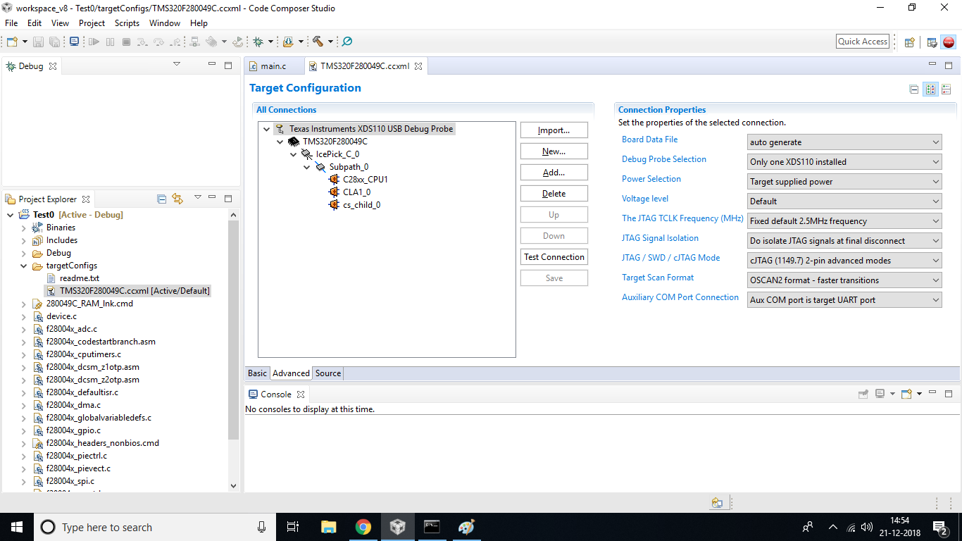
    2. Please verify that your Target configuration file is using cJTAG in 2-pin advanced mode.

    Thanks,
    Mark
  • Yes I have installed the older version of EMU i.e ti_emupack_setup_8.0.803.0_win_32.exe

    And the Target Configuration setting is  cJTAG in 2-pin advanced mode.

    But still the error is there.

  • It seems like something else must be going on.

    Can you run through the JTAG connectivity debug guide http://www.ti.com/lit/spracf0? If you are still unable to get the device working, please provide the information requested to post in e2e.

    -Mark

  • Payal,

    It has been more than a few days since your last reply. Please let me know if you are still facing this issue.

    Thanks,
    Mark
  • Hello Mark,

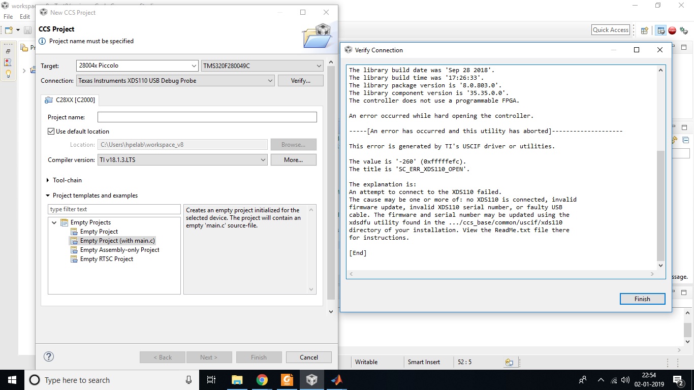
    While creating a new project and verifying the connection I am getting the same error.

    But while doing Connection Test in Target configuration setting. The Result is

    [Start: Texas Instruments XDS110 USB Debug Probe_0]

    Execute the command:

    %ccs_base%/common/uscif/dbgjtag -f %boarddatafile% -rv -o -S integrity

    [Result]


    -----[Print the board config pathname(s)]------------------------------------

    C:\Users\hpelab\AppData\Local\TEXASI~1\CCS\
    ti\0\0\BrdDat\testBoard.dat

    -----[Print the reset-command software log-file]-----------------------------

    This utility has selected a 100- or 510-class product.
    This utility will load the adapter 'jioxds110.dll'.
    The library build date was 'Sep 28 2018'.
    The library build time was '17:26:33'.
    The library package version is '8.0.803.0'.
    The library component version is '35.35.0.0'.
    The controller does not use a programmable FPGA.
    The controller has a version number of '5' (0x00000005).
    The controller has an insertion length of '0' (0x00000000).
    This utility will attempt to reset the controller.
    This utility has successfully reset the controller.

    -----[Print the reset-command hardware log-file]-----------------------------

    The scan-path will be reset by toggling the JTAG TRST signal.
    The controller is the XDS110 with USB interface.
    The link from controller to target is direct (without cable).
    The software is configured for XDS110 features.
    The controller cannot monitor the value on the EMU[0] pin.
    The controller cannot monitor the value on the EMU[1] pin.
    The controller cannot control the timing on output pins.
    The controller cannot control the timing on input pins.
    The scan-path link-delay has been set to exactly '0' (0x0000).

    -----[Perform the Integrity scan-test on the JTAG IR]------------------------

    This test will use blocks of 64 32-bit words.
    This test will be applied just once.

    Do a test using 0xFFFFFFFF.
    Scan tests: 1, skipped: 0, failed: 0
    Do a test using 0x00000000.
    Scan tests: 2, skipped: 0, failed: 0
    Do a test using 0xFE03E0E2.
    Scan tests: 3, skipped: 0, failed: 0
    Do a test using 0x01FC1F1D.
    Scan tests: 4, skipped: 0, failed: 0
    Do a test using 0x5533CCAA.
    Scan tests: 5, skipped: 0, failed: 0
    Do a test using 0xAACC3355.
    Scan tests: 6, skipped: 0, failed: 0
    All of the values were scanned correctly.

    The JTAG IR Integrity scan-test has succeeded.

    -----[Perform the Integrity scan-test on the JTAG DR]------------------------

    This test will use blocks of 64 32-bit words.
    This test will be applied just once.

    Do a test using 0xFFFFFFFF.
    Scan tests: 1, skipped: 0, failed: 0
    Do a test using 0x00000000.
    Scan tests: 2, skipped: 0, failed: 0
    Do a test using 0xFE03E0E2.
    Scan tests: 3, skipped: 0, failed: 0
    Do a test using 0x01FC1F1D.
    Scan tests: 4, skipped: 0, failed: 0
    Do a test using 0x5533CCAA.
    Scan tests: 5, skipped: 0, failed: 0
    Do a test using 0xAACC3355.
    Scan tests: 6, skipped: 0, failed: 0
    All of the values were scanned correctly.

    The JTAG DR Integrity scan-test has succeeded.

    [End: Texas Instruments XDS110 USB Debug Probe_0]

  • Do you by chance have the connection open in another window? Sometimes if you do a "test connection" while the debugger is connected in the Debug view, it will fail since one of them already has the resource taken.

    Again, please work through the JTAG connectivity debug guide I previously linked to. It provides many steps in an easy to follow flowchart. At the end of the document, if you are still unable to resolve the issue, provide the information requested. This will help us to debug the issue with the proper information.


    _Mark
  • Payal,

    Were you able to work through the debug guide?

    -Mark
  • Even though the verification error is still there. But the connection error has been resolved.

    Thanks

  • Ok. Well, if you start experiencing issues that you wish to resolve, please don't hesitate to post again.

    -Mark