This thread has been locked.

If you have a related question, please click the "Ask a related question" button in the top right corner. The newly created question will be automatically linked to this question.

TMS320F28035: Help Required regarding evaluating TMS320F28035 with Renesas ISL 94212

Part Number: TMS320F28035

Hello,
We are evaluating Renesas ISL94212 and TI TMS320F28035 (Further referred as 20835 for brevity).
28035 is the master
ISL94212 is the slave. it is responsible for getting battery parameters

28035 is connected to the daisy chain consisting of 2 ISL94212 devices in a proprietary manner. The master daisy chain device is connected with 28035 using SPI interface.


For this purpose we have

1. TI Evaluation Kit (docket board)

2. Renesas Evaluation Kit (ISL94212EVKIT1Z)

3. Modified the example code (SPI loopback example) to transmit the command and receive the response.

The relevant register settings are:

SpiaRegs.SPICCR.all =0x0087;

SpiaRegs.SPICTL.all =0x000E;

SpiaRegs.SPIBRR =0x007F;

Our connection is given in block diagram below:

We are facing problems as explained below. 

1. 28035 is able to send data to first ISL device over SPI (03 24 04) CRC is also calculated. The command is "identify".

2. The command transmission to ISL94212 is confirmed by waveform seen in CRO. The waveform is shown below
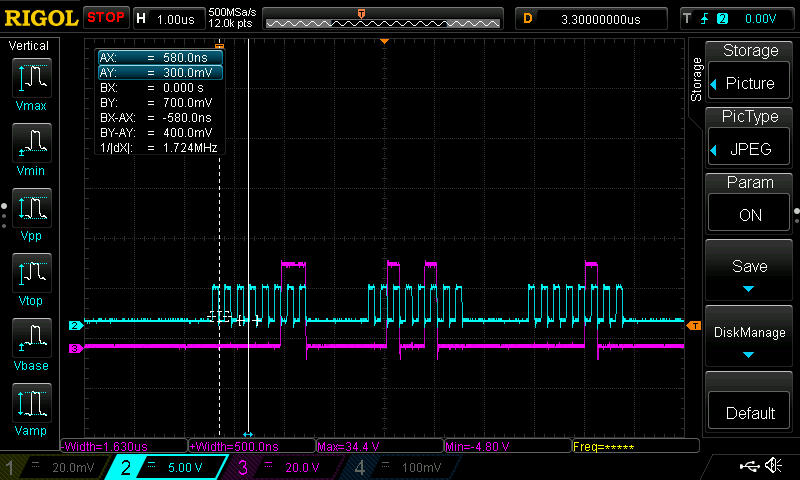
3. There is no response (not even acknowledge).

4. As written above, data sent over SPI is 03 24 04 and As per datasheet it should be 4 bytes and first three bytes should 03 30 0C indicating acknowledge by the first slave on SPI Line.

If we remove 28035 and connect the rest of daisy chain using to PC using Renesas USB to SPI converter (converts USB to SPI and vice versa) and use Renesas GUI, the GUI is able to communicate successfully.

However, we cannot see the parameters used by Renesas GUI to communicate with ISL94212 over SPI (clock polarity and phase, baud rate, etc). Further, since 28035 is not able to communicate successfully, we suspecting the communication between 28035 and ISL94212 is the problem.

We need to find out what is going on, why is ISL94212 nor responding in the way it should be

Can anyone please explain what is going on and what could be the problem?

Regards

Moreshwar Salpekar

  • Hi Moreshwar,

    This would appear to be an issue with the software on the Renesas device. As you mentioned, the data being transmitted by the f2803x device looks good.

    You need to make sure both devices are expecting the same format of code.

    sal
  • Hello All (Especially Sal), 

    Thanks for clarifying one point. We have been able to pursue with Renesas and have got partially around this issue. By Partially I mean following

    command from 28035: 0x03 0x24 0x04

    Expected Response from IS94212: 0x03 0x30 0x00 0x0C

    Actual response is 0x00 0x11 0x18 0x00

    What makes this weird is that CRO shows that ISL94212 is sending the correct response (i.e. CRO Shows 0x03 0x30 0x00 0x0C). It is just that read from TI RXBUF Reg is wrong. Can you please clarify why there is a difference between what is seen on CRO and what is read from the register? Am I missing something? 

    Since it is daisy chain the reading procedure is as follows:

    =========================

    1. While DATAREADY (DR) is asserted (Active Low)

    2. Assert CHIPSELECT (CS) (Active Low)

    3. Send a Dummy byte (I send 0x00) to activate the clock.

    4. Read the data from RXBUF and store in array.

    5. if DR is 0, go to step 1

    6. Return

    =========================

    Another point I am seeing is that sometimes at Step 6 DR = 0 even after loop exits. I exit loop only if DR is 1. However, I can see that DR again goes to 0 at step 6 implying ISL is still sending data. I tried increasing the delay before testing DR. I have also tried adding a double loop (two loops, both testing DR) as below

    =========================

    1. While DATAREADY (DR) is asserted (Active Low)

    2. While DR is asserted

    3. Assert CHIPSELECT (CS) (Active Low)

    4. Send a Dummy byte (I send 0x00) to activate the clock.

    5. Read the data from RXBUF and store in array.

    6. if DR is 0, go to step 2

    7. if DR is 0, go to step 1

    8. Return

    ==========================

    I tried adding a delay between 6 and 7 but no help.

    Both of the issues may be related or maybe not.

    Thanks in advance for answers.

    Regards

    Moreshwar Salpekar

  • Can you ensure the data length is aligned between both devices?

    The difference in values makes me think this is related to SPI communication format. Make data length bits, or stop bits.

    I will ask a SPI expert to look at your post as well.

    Hope this helps,
    sal
  • Hi,

    Looking at your SPI configuration, Polarity =0, Phase = 1. this is "Rising Edge with delay" refer to SPI Clocking Schemes section in the new F2803x TRM. So essentially, the SPI will Transmit data on the falling edge, and latch in the receive data on the rising edge (the SPICLK Signal Options Figure is useful for visualizing this) 

    • Can you show a capture of SPICLK, SPISIMO, and SPISOMI during a failing transmission?
    • Can you show a capture of the same, but when using the GUI instead of the F2803x as master?

    Please annotate these images, - which signal is which, what the data is expected to be, etc.

    Can you also explain the order of operations for the comms protocol? Your procedures in the last reply don't appear to be incorrect, but without knowing the protocol it is hard to be sure.

    • Does the master F2803x transmit the full command, then read back a full command?
    • Does the Master transmit 1 word command, then read back the response of that command?
    • Does Chip select need to toggle between each word?

    Thanks,
    Mark

  • Hello Mark,

    Thanks for pointing in the correct direction. I had a careful look at the waveforms and found out the issue was timing indeed (clock edges and delays). Now I am able to communicate and initialize the ISL94212 properly. I am now checking the rest of commands and hope they will work fine as well.

    Thanks again and thanks to Sal too.

    Regards

    Moreshwat