This thread has been locked.

If you have a related question, please click the "Ask a related question" button in the top right corner. The newly created question will be automatically linked to this question.

CCS/TMS320F28377S: usb_flash_programmer utility Error

Part Number: TMS320F28377S
Other Parts Discussed in Thread: C2000WARE,

Tool/software: Code Composer Studio

Hello,

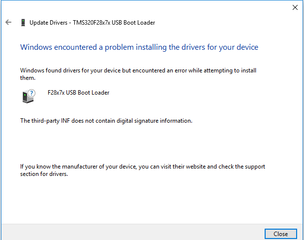
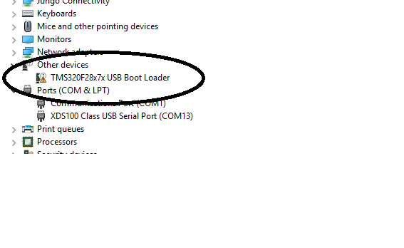
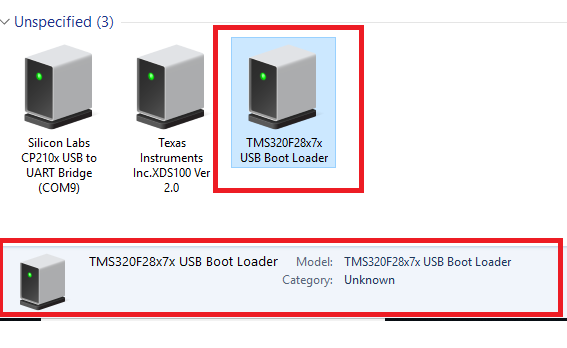
I want to program flash using usb_flash_programmer provided in c2000. I connect my microcontroller with PC via USB and on PC  message coming " TMS320F28X7X USB BOOT LOADER" (please see the screen shot)

But when I run usb_flash_programmer utility and use the example "blinky_cpu01" and "F2837xD_usb_flash_kernels_cpu01" using command  "usb_flash_programmer.exe  F2837xD_usb_flash_kernels_cpu01.dat  blinky_cpu01.dat"  then I getting message .

"

Error enumerating device interface: 0x0103

This may mean that the device is not attached or the driver is not installed

Error: Couldn't open the USB device

PS C:\ti\c2000\C2000Ware_1_00_06_00\utilities\flash_programmers\usb_flash_programmer>

"

I think this error come because I am using example file for F2837xD and I am using TMS320F28377S. So please tell how to generate .dat files both files for TMS320F28377S. 


  • Hello,

    Concerned experts have been notified.
    Please note that the response might be delayed due to holidays.

    Regards,
    Sudhakar
  • Hi,

    I don't think this has anything to do with xD versus xS.

    Can you ensure you are using the latest Windows Drivers in C2000Ware please? Uninstall and delete old drivers and make sure you are using the latest driver.

    sal
  • C2000 version is C2000Ware_1_00_06_00.
  • And driver version 1.2.9270.0 

  • As you told I install present driver and update driver in from c2000 from following path.

    C:\ti\c2000\C2000Ware_1_00_06_00\utilities\flash_programmers\usb_flash_programmer\windows_driver.

    but I getting this message while installation. 

    and devise is detected as 

    So please help to solve this. And if there is any updated driver file then please give share the link.

  • Hi,

    Please delete and uninstall the old drivers from your system. We have had to do this in the past. Sometimes Windows will still pick up the previous driver if they are not uninstalled and deleted. Save off the latest driver somewhere and delete all the old ones. Then point Windows to the latest driver.

    See if this helps. We have had success and others have had success doing this. And they have gotten the bootloader and usb flash programmer working successfully with ease.

    sal
  • Thanks,

    My driver issue is resolved,

    But when I run USB flash programmer utility then I get this error

    "Sending 9784 bytes of data from file Loader_Test_Converted.dat...
    Error sending bulk transfer: 0x0079
    64 out of 9784 bytes sent
    USB operation failed!"

    and another error is. 

    "Error reading manufacturer string: 790000
    USB operation failed!
    PS C:\ti\c2000\C2000Ware_1_00_06_00\utilities\flash_programmers\usb_flash_programmer>"

    This come when I again run flash programmer 

    Please tell what is this ? and how to resolve this ?

  • It appears the device is enumerating properly now.

    Also, you need to make sure the data you are sending is in the proper boot loader format. This is detailed in the Boot ROM chapter of the TRM. The data is expected to be in a specific hex format using the hex2000 utility.

    You may have to debug this using the Visual Studio project for the usb flash programmer.

    sal
  • Now I am able to program using usb flash utility. And I want to call USB boot loader from my application program in microcontroller. For this I include USB boot file in my project from location "C:\ti\c2000\C2000Ware_1_00_06_00\libraries\boot_rom\f2837xs\revB" . When I compile my project I getting this error.

    "
    unresolved symbol _c1brom_enable_pie_in_boot, first referenced in ./Source/USB_Boot.obj S
    "

    this function is declared extern in c1_bootrom.h but I not found the definition of function. so please tell where it is, and which file is needed to add??
  • You need to include the Boot ROM .lib file into your CCS project.

    You can find the FPU and non-FPU version here: C:\ti\c2000\C2000Ware_1_00_06_00\libraries\boot_rom\f2837xs\revB\rom_symbol_libs\c1_ROM_API

    sal
  • I include "F2837xRevB_c1bootROM_BootROMSymbols.lib" in my project but error is unresolved.

    This is the screen shot of my project and you can see the file structure and USB_Boot.c and other files but error still comes.

    Ans as I mention in previously post that I want to call usb boot loader from my code. So can you give any code for same.

  • I don't see the .lib added to your project in the Project Explorer.

    If you add the Boot ROM .lib then you should not have to add the boot ROM source files. The source already resides in the ROM. By including the .lib you are then able to make function calls into the ROM code.

    sal
  • Hi,

    As you suggest I add usb boot.lib file. But still I getting error. I attach a document to explain what I did and my project code (I use gpio_toggle_cpu01 example and call usb boot lib). So can you tell what is wrong in this and please also suggest some solution.

    7041.doc1.docx

    usb test1.zip 

  • Hi Sam,

    I got your CCS project building. Since your CCS project has enabled FPU support, please include this file: F2837xRevB_c1bootROM_BootROMSymbols_fpu32.lib

    Do not include the non-fpu version. But instead include the fpu version of the library.

    Additionally, I saw in your Word document that you added the file to your include option. You do not need to do this. Additionally, you should not add files to the include path, but only directories.

    Hope this helps.
    sal
  • Additionally, You should call USB_Boot() and not USB_Boot_Init().

    1) Add the Boot ROM symbols library with fpu support (if your project is using fpu).

    2) Call USB_Boot() in your appplication.

    3) In the file which calls USB_Boot() add an extern prototype for the function: extern Uint32 USB_Boot(Uint16 bootMode);

    Please see the CCS project attached in the ZIP.

    Regards,

    sal

    usb_test1_sal.zip

  • Thanks SAL,

    Now my microcontroller  is coming in boot mode from my code and microcontroller is also detected on PC as "TMS320F28x7x USB Boot Loader".

    But when I run USB flash programmer I getting this

    /***************************************************************************************************************/
    "Manufacturer: Texas Instruments
    Product ID: TMS320F28x7x USB Boot Loader
    Serial number: 2

    Sending 14206 bytes of data from file F2837xD_usb_flash_kernels_cpu01.dat... done!
    14206 out of 14206 bytes sent
    Success!
    Error enumerating device interface: 0x0103
    This may mean that the device is not attached or the driver is not installed
    Error: Couldn't open the USB device
    PS C:\ti\c2000\C2000Ware_1_00_06_00\utilities\flash_programmers\usb_flash_programmer>
    "
    /****************************************************************************************************************/
    So initially 14206 bytes send to micocontroller then this error come.

    One more thing in function USB_Boot I pass 0XC5A but when I see this function, passed value is not doing anything.

    This is my code...

    /****************************************************************************************************************/
    extern Uint32 USB_Boot(Uint16 bootMode);

    void main(void)
    {
    //
    // Step 1. Initialize System Control:
    // PLL, WatchDog, enable Peripheral Clocks
    // This example function is found in the F2837xS_SysCtrl.c file.
    //
    InitSysCtrl();

    Gpio_select();

    DINT;

    InitPieCtrl();

    IER = 0x0000;
    IFR = 0x0000;

    InitPieVectTable();

    USB_Boot(0xC5A); //call bootloader for reprogramming.

    Gpio_example1();

    }

  • Hi,

    You are correct, the passed value is not necessary in this function.

    Can you make sure the USB flash kernel is built properly? Can you build the kernel and make sure it runs from RAM using CCS and test it with the usb flash programmer first? Then load it to RAM using the USB bootloader. There are some build options for the kernel, make sure you have selected the proper build option.

    Make sure you can get the most simple way working first, then move to the more complicated implementation.

    sal
  • SAL,

    I am using "F2837xD_usb_flash_kernels_cpu01" given in f2837xD_fw_upgrade_example folder. And when I try this using Memory Browser by writing 0XC5A on location 0XD00 it works fine and program is also updated(please see log below). So is there anything else needed ???

    "Sending 14206 bytes of data from file F2837xD_usb_flash_kernels_cpu01.dat... done!
    14206 out of 14206 bytes sent
    Success!
    Manufacturer: Texas Instruments
    Product ID: TMS320F28x7x USB Boot Loader
    Serial number: 2

    Sending 118292 bytes of data from file TEST_01.dat... done!
    118292 out of 118292 bytes sent
    Success!
    PS C:\ti\c2000\C2000Ware_1_00_06_00\utilities\flash_programmers\usb_flash_programmer>
    "

    I again try with "USB_Boot" function and place it just before while(1). Microcontroller detected on PC, but same error comes when I try to run USB FLASH PROGRAMMER(see log below).

    "

    Error enumerating device interface: 0x0103
    This may mean that the device is not attached or the driver is not installed
    Error: Couldn't open the USB device
    PS C:\ti\c2000\C2000Ware_1_00_06_00\utilities\flash_programmers\usb_flash_programmer>

    "

    One more thing When I run above code using debugger then only microcontroller is detected on PC but when I disconnect debugger and restart (turn off power and then on) then microcontroller not detected (i use function USB_BOOT before while(1)).

  • Hello Sal,

    I have tried it on TMS320F2837xD control card with example utility code given in usb_flash_programmer. When i am working it using emulation mode, everything seems working but when I have programmed my MCU with below code for calling USB mode with application:

    //
    // Main
    //
    void main(void)
    {
    uint32_t EntryAddr = 0xFFFFFFFF;
    //
    // Step 1. Initialize System Control:
    // PLL, WatchDog, enable Peripheral Clocks
    // This example function is found in the F2837xS_SysCtrl.c file.
    //
    InitSysCtrl();

    //
    // Step 2. Initialize GPIO:
    // This example function is found in the F2837xS_Gpio.c file and
    // illustrates how to set the GPIO to it's default state.
    Gpio_select();

    //
    // Step 3. Clear all __interrupts and initialize PIE vector table:
    // Disable CPU __interrupts
    //
    DINT;

    //
    // Initialize PIE control registers to their default state.
    // The default state is all PIE __interrupts disabled and flags
    // are cleared.
    // This function is found in the F2837xS_PieCtrl.c file.
    //
    InitPieCtrl();

    //
    // Disable CPU __interrupts and clear all CPU __interrupt flags:
    //
    IER = 0x0000;
    IFR = 0x0000;

    //
    // Initialize the PIE vector table with pointers to the shell Interrupt
    // Service Routines (ISR).
    // This will populate the entire table, even if the __interrupt
    // is not used in this example. This is useful for debug purposes.
    // The shell ISR routines are found in F2837xS_DefaultIsr.c.
    // This function is found in F2837xS_PieVect.c.
    //
    InitPieVectTable();

    //***************************************************************//

    /* enable C1 NMI*/
    EALLOW;
    NmiIntruptRegs.NMICFG.bit.NMIE = 1;
    c1brom_handle_nmi_at_start();

    InitDCSM();


    USB_Boot(0xC); //call bootloader for reprogramming.
    if((EntryAddr != 0xFFFFFFFF) &&
    (EntryAddr != 0x00000000))
    {
    /*if OTP is programmed, then call OTP function*/
    ((void (*)(void))EntryAddr)();
    }
    sysctl_wdog_enable();

    //*****************************************************************//

    #if EXAMPLE1

    //
    // This example uses DATA registers to toggle I/O's
    //
    Gpio_example1();

    #endif // - EXAMPLE1

    }

    TMS320F2837xD comes in Boot mode & its driver get detected. Now when i have executed command 

    usb_flash_programmer.exe  F2837xD_usb_flash_kernels_cpu01.dat  blinky_cpu01.dat

    It program usb_flash kenel in RAM but looks like that program is not getting started and further USB driver is not getting detected. I am also getting same error on command prompt:

    Please check this at your end and advise its solution...

    Regards,

    Vikas Chola

  • Hi,

    If what you showed me above is what you have built and programmed, then the error is pretty obvious I think and also could have been identified by setting a breakpoint after the USB_Boot() function call.

    This is what you have:

    uint32_t EntryAddr = 0xFFFFFFFF;
    ...
    USB_Boot(0xC); //call bootloader for reprogramming.
    if((EntryAddr != 0xFFFFFFFF) &&
    (EntryAddr != 0x00000000))
    {
    /*if OTP is programmed, then call OTP function*/
    ((void (*)(void))EntryAddr)();
    }

    You have set EntryAddr as 0xFFFFFFF so it never makes the function call to the code you just programmed using the bootloader.

    You need to set EntryAddr to the return value of the boot function. EntryAddr = USB_Boot(BootMode);

    Also, please attempt to debug your code using CCS and breakpoints, single -stepping and running through your code in order to identify the behavior and potential causes of why your code is not doing what you expect. In this case it should have been pretty obvious if you set a breakpoint after the USB_Boot() function call.

    Hope this helps.
    sal
  • SAL,

    As you suggest I try single stepping and I found that in emulation mode USB_BOOT function is work as expected. But when I run same code in standalone mode then it not work and I always get error on command promont when I run usb flash programmer.

    I try two methods to verify this.

    1) I use a ADC interrupt and toggle a GPIO inside interrupt. In start till "USB_BOOT" is not called, GPIO toggled but when program reach on USB_BOOT then GPIO stop toggling. So I think application program call USB_BOOT and ADC interrupt stop working.
    I test this both in emulation mode and standalone mode and results are same as I mentioned.

    2) I use below program and toggle gpio before calling USB_BOOT and GPIO toggle as expected but when it reach USB_BOOT, microcontroller detected on PC and I am able to program microcontroller but only in emulation mode. In standalone mode this not work.

    So please test this below code at your end and tell what mistake I am doing.


    //
    // Included Files
    //
    #include "F28x_Project.h"
    #include "sysctl.h"

    //
    // Select the example to compile in. Only one example should be set as 1
    // the rest should be set as 0.
    //
    #define EXAMPLE1 1 // Use DATA registers to toggle I/O's
    #define EXAMPLE2 0 // Use SET/CLEAR registers to toggle I/O's
    #define EXAMPLE3 0 // Use TOGGLE registers to toggle I/O's

    //
    // Function Prototypes
    //
    void delay_loop(void);
    void Gpio_select(void);
    void Gpio_example1(void);
    void Gpio_example2(void);
    void Gpio_example3(void);
    extern Uint32 USB_Boot(Uint16 bootMode);
    extern void InitDCSM();
    extern void c1brom_handle_nmi_at_start();
    //extern SysCtl_resetDevice();

    //
    // Main
    //
    void main(void)
    {
    uint32_t EntryAddr = 0xFFFFFFFF;
    //
    // Step 1. Initialize System Control:
    // PLL, WatchDog, enable Peripheral Clocks
    // This example function is found in the F2837xD_SysCtrl.c file.
    //
    InitSysCtrl();


    //
    // Step 2. Initialize GPIO:
    // This example function is found in the F2837xD_Gpio.c file and
    // illustrates how to set the GPIO to it's default state.
    Gpio_select();

    //
    // Step 3. Clear all __interrupts and initialize PIE vector table:
    // Disable CPU __interrupts
    //
    DINT;

    //
    // Initialize PIE control registers to their default state.
    // The default state is all PIE __interrupts disabled and flags
    // are cleared.
    // This function is found in the F2837xD_PieCtrl.c file.
    //
    InitPieCtrl();

    //
    // Disable CPU __interrupts and clear all CPU __interrupt flags:
    //
    IER = 0x0000;
    IFR = 0x0000;

    //
    // Initialize the PIE vector table with pointers to the shell Interrupt
    // Service Routines (ISR).
    // This will populate the entire table, even if the __interrupt
    // is not used in this example. This is useful for debug purposes.
    // The shell ISR routines are found in F2837xD_DefaultIsr.c.
    // This function is found in F2837xD_PieVect.c.
    //
    InitPieVectTable();
    Gpio_example1();

    /* enable C1 NMI*/
    EALLOW;
    NmiIntruptRegs.NMICFG.bit.NMIE = 1;
    c1brom_handle_nmi_at_start();

    InitDCSM();

    EntryAddr=USB_Boot(0xC); //call bootloader for reprogramming.
    // if((EntryAddr != 0xFFFFFFFF) && (EntryAddr != 0x00000000))
    // {
    /*if OTP is programmed, then call OTP function*/
    ((void (*)(void))EntryAddr)();
    // }
    //sysctl_wdog_enable();
    // return EntryAddr;


    //
    // Step 4. User specific code:
    //
    #if EXAMPLE1

    //
    // This example uses DATA registers to toggle I/O's
    //
    Gpio_example1();

    #endif // - EXAMPLE1

    #if EXAMPLE2

    //
    // This example uses SET/CLEAR registers to toggle I/O's
    //
    Gpio_example2();

    #endif

    #if EXAMPLE3

    //
    // This example uses TOGGLE registers to toggle I/O's
    //
    Gpio_example3();

    #endif
    }

    //
    // delay_loop - Delay function
    //
    void delay_loop()
    {
    long i;
    for (i = 0; i < 1000000; i++) {}
    }

    //
    // Gpio_example1 - Example 1: Toggle I/Os using DATA registers
    //
    void Gpio_example1(void)
    {
    unsigned int i;
    for(i=0;i<20;i++)
    {
    GpioDataRegs.GPADAT.all = 0xAAAAAAAA;
    GpioDataRegs.GPBDAT.all = 0x00000AAA;
    delay_loop();

    GpioDataRegs.GPADAT.all = 0x55555555;
    GpioDataRegs.GPBDAT.all = 0x00001555;
    delay_loop();
    }
    }

    //
    // Gpio_example2 - Example 2: Toggle I/Os using SET/CLEAR registers
    //
    void Gpio_example2(void)
    {
    for(;;)
    {
    GpioDataRegs.GPASET.all = 0xAAAAAAAA;
    GpioDataRegs.GPACLEAR.all = 0x55555555;

    GpioDataRegs.GPBSET.all = 0x00000AAA;
    GpioDataRegs.GPBCLEAR.all = 0x00001555;

    delay_loop();

    GpioDataRegs.GPACLEAR.all = 0xAAAAAAAA;
    GpioDataRegs.GPASET.all = 0x55555555;

    GpioDataRegs.GPBCLEAR.all = 0x00000AAA;
    GpioDataRegs.GPBSET.all = 0x00001555;

    delay_loop();
    }
    }

    //
    // Gpio_example3 - Example 3: Toggle I/Os using TOGGLE registers
    //
    void Gpio_example3(void)
    {
    //
    // Set pins to a known state
    //
    GpioDataRegs.GPASET.all = 0xAAAAAAAA;
    GpioDataRegs.GPACLEAR.all = 0x55555555;

    GpioDataRegs.GPBSET.all = 0x00000AAA;
    GpioDataRegs.GPBCLEAR.all = 0x00001555;

    //
    // Use TOGGLE registers to flip the state of
    // the pins.
    // Any bit set to a 1 will flip state (toggle)
    // Any bit set to a 0 will not toggle.
    //
    for(;;)
    {
    GpioDataRegs.GPATOGGLE.all =0xFFFFFFFF;
    GpioDataRegs.GPBTOGGLE.all =0x00001FFF;

    delay_loop();
    }
    }

    //
    // Gpio_select - Configure GPIO muxing and pin outputs
    //
    void Gpio_select(void)
    {
    EALLOW;
    GpioCtrlRegs.GPAMUX1.all = 0x00000000; // All GPIO
    GpioCtrlRegs.GPAMUX2.all = 0x00000000; // All GPIO
    GpioCtrlRegs.GPBMUX1.all = 0x00000000; // All GPIO
    GpioCtrlRegs.GPADIR.all = 0xFFFFFFFF; // All outputs
    GpioCtrlRegs.GPBDIR.all = 0x00001FFF; // All outputs
    EDIS;
    }

    //
    // End of file
    //
  • Hi,

    If your GPIO toggle program loaded and running from RAM or flash?

    If it is running from RAM, you must know that the USB bootloader is loading code into RAM. When you are loading the kernel into RAM it may be overwriting your GPIO toggle program if it is loaded to RAM. Therefore, the program will not work as expected.

    Please make sure the code which is calling USB_Boot() and then branching to the kernel which is loaded to RAM by the bootloader resides either in flash or a location which is not being overwritten by the loader.

    sal
  • //###########################################################################
    //
    // FILE:    GpioToggle.c
    //
    // TITLE:   GPIO toggle test program.
    //
    //! \addtogroup cpu01_example_list
    //! <h1>GPIO toggle test program (GpioToggle)</h1>
    //!
    //! Three different examples are included. Select the example
    //! (data, set/clear or toggle) to execute before compiling using
    //! the #define statements found at the top of the code.
    //!
    //! Toggle all of the GPIO PORT pins
    //!
    //! The pins can be observed using Oscilloscope.
    //!
    //
    //###########################################################################
    // $TI Release: F2837xD Support Library v3.05.00.00 $
    // $Release Date: Thu Oct 18 15:48:42 CDT 2018 $
    // $Copyright:
    // Copyright (C) 2013-2018 Texas Instruments Incorporated - http://www.ti.com/
    //
    // Redistribution and use in source and binary forms, with or without 
    // modification, are permitted provided that the following conditions 
    // are met:
    // 
    //   Redistributions of source code must retain the above copyright 
    //   notice, this list of conditions and the following disclaimer.
    // 
    //   Redistributions in binary form must reproduce the above copyright
    //   notice, this list of conditions and the following disclaimer in the 
    //   documentation and/or other materials provided with the   
    //   distribution.
    // 
    //   Neither the name of Texas Instruments Incorporated nor the names of
    //   its contributors may be used to endorse or promote products derived
    //   from this software without specific prior written permission.
    // 
    // THIS SOFTWARE IS PROVIDED BY THE COPYRIGHT HOLDERS AND CONTRIBUTORS 
    // "AS IS" AND ANY EXPRESS OR IMPLIED WARRANTIES, INCLUDING, BUT NOT 
    // LIMITED TO, THE IMPLIED WARRANTIES OF MERCHANTABILITY AND FITNESS FOR
    // A PARTICULAR PURPOSE ARE DISCLAIMED. IN NO EVENT SHALL THE COPYRIGHT 
    // OWNER OR CONTRIBUTORS BE LIABLE FOR ANY DIRECT, INDIRECT, INCIDENTAL, 
    // SPECIAL, EXEMPLARY, OR CONSEQUENTIAL DAMAGES (INCLUDING, BUT NOT 
    // LIMITED TO, PROCUREMENT OF SUBSTITUTE GOODS OR SERVICES; LOSS OF USE,
    // DATA, OR PROFITS; OR BUSINESS INTERRUPTION) HOWEVER CAUSED AND ON ANY
    // THEORY OF LIABILITY, WHETHER IN CONTRACT, STRICT LIABILITY, OR TORT 
    // (INCLUDING NEGLIGENCE OR OTHERWISE) ARISING IN ANY WAY OUT OF THE USE 
    // OF THIS SOFTWARE, EVEN IF ADVISED OF THE POSSIBILITY OF SUCH DAMAGE.
    // $
    //###########################################################################
    
    //
    // Included Files
    //
    #include "F28x_Project.h"
    #include "sysctl.h"
    
    //
    // Select the example to compile in.  Only one example should be set as 1
    // the rest should be set as 0.
    //
    #define EXAMPLE1 1  // Use DATA registers to toggle I/O's
    #define EXAMPLE2 0  // Use SET/CLEAR registers to toggle I/O's
    #define EXAMPLE3 0  // Use TOGGLE registers to toggle I/O's
    
    //
    // Function Prototypes
    //
    void delay_loop(void);
    void Gpio_select(void);
    void Gpio_example1(void);
    void Gpio_example2(void);
    void Gpio_example3(void);
    extern Uint32 USB_Boot(Uint16 bootMode);
    extern void InitDCSM();
    extern void c1brom_handle_nmi_at_start();
    //extern SysCtl_resetDevice();
    
    //
    // Main
    //
    void main(void)
    {
        uint32_t    EntryAddr = 0xFFFFFFFF;
    //
    // Step 1. Initialize System Control:
    // PLL, WatchDog, enable Peripheral Clocks
    // This example function is found in the F2837xD_SysCtrl.c file.
    //
       InitSysCtrl();
    
    
    //
    // Step 2. Initialize GPIO:
    // This example function is found in the F2837xD_Gpio.c file and
    // illustrates how to set the GPIO to it's default state.
       Gpio_select();
    
    //
    // Step 3. Clear all __interrupts and initialize PIE vector table:
    // Disable CPU __interrupts
    //
       DINT;
    
    //
    // Initialize PIE control registers to their default state.
    // The default state is all PIE __interrupts disabled and flags
    // are cleared.
    // This function is found in the F2837xD_PieCtrl.c file.
    //
       InitPieCtrl();
    
    //
    // Disable CPU __interrupts and clear all CPU __interrupt flags:
    //
       IER = 0x0000;
       IFR = 0x0000;
    
    //
    // Initialize the PIE vector table with pointers to the shell Interrupt
    // Service Routines (ISR).
    // This will populate the entire table, even if the __interrupt
    // is not used in this example.  This is useful for debug purposes.
    // The shell ISR routines are found in F2837xD_DefaultIsr.c.
    // This function is found in F2837xD_PieVect.c.
    //
       InitPieVectTable();
       Gpio_example1();
    
       /* enable C1 NMI*/
           EALLOW;
           NmiIntruptRegs.NMICFG.bit.NMIE = 1;
           c1brom_handle_nmi_at_start();
    
           InitDCSM();


           EntryAddr=USB_Boot(0xC); //call bootloader for reprogramming.
      // if((EntryAddr != 0xFFFFFFFF) && (EntryAddr != 0x00000000))
      //         {
                   /*if OTP is programmed, then call OTP function*/
                   ((void (*)(void))EntryAddr)();
       //        }
       //sysctl_wdog_enable();
      //     return EntryAddr;
    
    
    //
    // Step 4. User specific code:
    //
    #if EXAMPLE1
    
        //
        // This example uses DATA registers to toggle I/O's
        //
        Gpio_example1();
    
    #endif  // - EXAMPLE1
    
    #if EXAMPLE2
    
        //
        // This example uses SET/CLEAR registers to toggle I/O's
        //
        Gpio_example2();
    
    #endif
    
    #if EXAMPLE3
    
        //
        // This example uses TOGGLE registers to toggle I/O's
        //
        Gpio_example3();
    
    #endif
    }
    
    //
    // delay_loop - Delay function
    //
    void delay_loop()
    {
        long i;
        for (i = 0; i < 1000000; i++) {}
    }
    
    //
    // Gpio_example1 - Example 1: Toggle I/Os using DATA registers
    //
    void Gpio_example1(void)
    {
        unsigned int i;
       for(i=0;i<20;i++)
       {
          GpioDataRegs.GPADAT.all = 0xAAAAAAAA;
          GpioDataRegs.GPBDAT.all = 0x00000AAA;
          delay_loop();
    
          GpioDataRegs.GPADAT.all = 0x55555555;
          GpioDataRegs.GPBDAT.all = 0x00001555;
          delay_loop();
        }
    }
    
    //
    // Gpio_example2 - Example 2: Toggle I/Os using SET/CLEAR registers
    //
    void Gpio_example2(void)
    {
       for(;;)
       {
           GpioDataRegs.GPASET.all = 0xAAAAAAAA;
           GpioDataRegs.GPACLEAR.all = 0x55555555;
    
           GpioDataRegs.GPBSET.all = 0x00000AAA;
           GpioDataRegs.GPBCLEAR.all = 0x00001555;
    
           delay_loop();
    
           GpioDataRegs.GPACLEAR.all = 0xAAAAAAAA;
           GpioDataRegs.GPASET.all = 0x55555555;
    
           GpioDataRegs.GPBCLEAR.all = 0x00000AAA;
           GpioDataRegs.GPBSET.all = 0x00001555;
    
           delay_loop();
        }
    }
    
    //
    // Gpio_example3 - Example 3: Toggle I/Os using TOGGLE registers
    //
    void Gpio_example3(void)
    {
       //
       // Set pins to a known state
       //
       GpioDataRegs.GPASET.all = 0xAAAAAAAA;
       GpioDataRegs.GPACLEAR.all = 0x55555555;
    
       GpioDataRegs.GPBSET.all = 0x00000AAA;
       GpioDataRegs.GPBCLEAR.all = 0x00001555;
    
       //
       // Use TOGGLE registers to flip the state of
       // the pins.
       // Any bit set to a 1 will flip state (toggle)
       // Any bit set to a 0 will not toggle.
       //
       for(;;)
       {
          GpioDataRegs.GPATOGGLE.all =0xFFFFFFFF;
          GpioDataRegs.GPBTOGGLE.all =0x00001FFF;
    
          delay_loop();
       }
    }
    
    //
    // Gpio_select - Configure GPIO muxing and pin outputs
    //
    void Gpio_select(void)
    {
        EALLOW;
        GpioCtrlRegs.GPAMUX1.all = 0x00000000;  // All GPIO
        GpioCtrlRegs.GPAMUX2.all = 0x00000000;  // All GPIO
        GpioCtrlRegs.GPBMUX1.all = 0x00000000;  // All GPIO
        GpioCtrlRegs.GPADIR.all = 0xFFFFFFFF;   // All outputs
        GpioCtrlRegs.GPBDIR.all = 0x00001FFF;   // All outputs
        EDIS;
    }
    
    //
    // End of file
    //
    

    SAL,

    Program calling USB_BOOT is in flash, in both case, as you can see in program(in my previous post)

    I toggle pins to confirm that microcontroller is entering in boot mode and as I said that when it is entering in boot mode GPIO stop toggling and same is expected.

    The main problem is in stand alone mode. In standalone mode when we run flash programmer error come but in emulation mode microcontroller has detected on PC and also work properly.

    And I have already send my code (attachment) so please test it at your end. My final goal is to program microcontroller using USB flash programmer in stand alone mode. Actually we are doing this to update firmware at customer side where use of debugger is not possible.

  • Hi,

    Harshmeet and I will look at this together on Monday morning.

    For now, please ensure that in standalone mode you have disabled the watchdog. It may be possible that you are experiencing a watchdog reset from standalone mode which is preventing the USB function from working as expected. Perhaps in emulation mode the GEL file or some setup file is disabling watchdog while the standalone code is not.

    We will get back with you on Monday.

    sal
  • SAL,

    I already use "DisableDog()" function to disable watchdog. I call it just before the calling "USB_BOOT" function. And this making no effect.

    "
    DisableDog(); //Disable watchdog
    USB_Boot(0x8AA); //Call to USB_Boot function
    "
  • Hi Sam,

    We have replicated the issue. We have seen the code enumerate and update the flash in emulation mode. But we were also unsuccessful from standalone mode booting to flash.

    Let me offer you and Harshmeet some suggestions as we further debug this.

    1) Remove all set-up code from your main() and simply call the USB_Boot() function. Then try the solution.

    2) If that doesn't work, my suspicion is that this may be related to configuring AUXCLK. In this case, then add some code to your main before calling USB_Boot() to configure XCLKOUT. Have AUXCLK output to XCLKOUT and check the frequency using an oscilloscope. The frequency should be 60 MHz. Let me know what the frequency is.

    3) As a final test, configure AUXCLK for 60 MHz like the USB boot loader does in your main, and then call USB_Boot().

    Above are three steps you can take to further debug this and try to get it working.

    The good news is that we have it working from emulation. We now need to figure out why it isn't working from standalone, which I admit is a little weird.

    Regards,
    sal
  • SAL,

    Any update ??

    I try as you suggest but result are same.
  • Can you use XCLKOUT to signal the frequency of AUXCLK? What is the frequency?

    sal
  • SAL,

    I am not getting any clock on XCLKOUT but I think this is due to wrong configuration but

    as you suggest I configure AUX clock just before calling "USB_BOOT". I done this in following code .

    /**************************************************************************************************************************************************/
    "
    DisableDog();

    EALLOW;

    ClkCfgRegs.CLKSRCCTL2.bit.AUXOSCCLKSRCSEL = 0x1; //Use XTAL (20 MHz) as the aux PLL clock source
    ClkCfgRegs.AUXPLLMULT.all = 6; //Set IMULT to 6, clear FMULT - 120MHz
    ClkCfgRegs.AUXPLLCTL1.bit.PLLEN = 1; //Enable the aux PLL
    ClkCfgRegs.AUXCLKDIVSEL.bit.AUXPLLDIV = 2/2; //Set AUXPLLDIV to 2
    while (ClkCfgRegs.AUXPLLSTS.bit.LOCKS != 1) {;} //Wait for the PLL to lock

    EDIS;

    USB_Boot(0x8AA);
    "

    /**************************************************************************************************************************************************/


    Here microcontroller is detected in standalone mode , but still flash programmer is not working and I get following error on console.

    /**************************************************************************************************************************************************/

    "

    Sending 14206 bytes of data from file F2837xD_usb_flash_kernels_cpu01.dat... done!

    14206 out of 14206 bytes sent

    Success!
    Error enumerating device interface: 0x0103
    This may mean that the device is not attached or the driver is not installed
    Error: Couldn't open the USB device
    "
    /**************************************************************************************************************************************************/


    I think problem is with USB FLASH KERNEL because when I run above code, microcontroller is detected on PC (in standalone mode also) but when USB FLASH KERNEL is transferred in to microcontroller. PC stop detecting microcontroller so please test above code at your end.

  • Hi Sam,

    Glad to see some progress. Harshmeet and I will debug this some more today and tomorrow and get back to you.

    In the meantime, you can add the AUXCLK configuration code to the kernel as well.

    You can try using the below code after calling InitSysCtrl():
    void InitAuxPll(Uint16 clock_source, Uint16 imult, Uint16 fmult, Uint16 divsel)

    I believe the issues we are seeing are having to do with clocking. That is why getting XCLKOUT working would be helpful as well.

    sal
  • Hi sam,

    Can you please try using this file?

    Regards

    Harshmeet

    //###########################################################################
    //
    // FILE:    GpioToggle.c
    //
    // TITLE:   GPIO toggle test program.
    //
    //! \addtogroup cpu01_example_list
    //! <h1>GPIO toggle test program (GpioToggle)</h1>
    //!
    //! Three different examples are included. Select the example
    //! (data, set/clear or toggle) to execute before compiling using
    //! the #define statements found at the top of the code.
    //!
    //! Toggle all of the GPIO PORT pins
    //!
    //! The pins can be observed using Oscilloscope.
    //!
    //
    //###########################################################################
    // $TI Release: F2837xD Support Library v3.05.00.00 $
    // $Release Date: Thu Oct 18 15:48:42 CDT 2018 $
    // $Copyright:
    // Copyright (C) 2013-2018 Texas Instruments Incorporated - http://www.ti.com/
    //
    // Redistribution and use in source and binary forms, with or without 
    // modification, are permitted provided that the following conditions 
    // are met:
    // 
    //   Redistributions of source code must retain the above copyright 
    //   notice, this list of conditions and the following disclaimer.
    // 
    //   Redistributions in binary form must reproduce the above copyright
    //   notice, this list of conditions and the following disclaimer in the 
    //   documentation and/or other materials provided with the   
    //   distribution.
    // 
    //   Neither the name of Texas Instruments Incorporated nor the names of
    //   its contributors may be used to endorse or promote products derived
    //   from this software without specific prior written permission.
    // 
    // THIS SOFTWARE IS PROVIDED BY THE COPYRIGHT HOLDERS AND CONTRIBUTORS 
    // "AS IS" AND ANY EXPRESS OR IMPLIED WARRANTIES, INCLUDING, BUT NOT 
    // LIMITED TO, THE IMPLIED WARRANTIES OF MERCHANTABILITY AND FITNESS FOR
    // A PARTICULAR PURPOSE ARE DISCLAIMED. IN NO EVENT SHALL THE COPYRIGHT 
    // OWNER OR CONTRIBUTORS BE LIABLE FOR ANY DIRECT, INDIRECT, INCIDENTAL, 
    // SPECIAL, EXEMPLARY, OR CONSEQUENTIAL DAMAGES (INCLUDING, BUT NOT 
    // LIMITED TO, PROCUREMENT OF SUBSTITUTE GOODS OR SERVICES; LOSS OF USE,
    // DATA, OR PROFITS; OR BUSINESS INTERRUPTION) HOWEVER CAUSED AND ON ANY
    // THEORY OF LIABILITY, WHETHER IN CONTRACT, STRICT LIABILITY, OR TORT 
    // (INCLUDING NEGLIGENCE OR OTHERWISE) ARISING IN ANY WAY OUT OF THE USE 
    // OF THIS SOFTWARE, EVEN IF ADVISED OF THE POSSIBILITY OF SUCH DAMAGE.
    // $
    //###########################################################################
    
    //
    // Included Files
    //
    #include "F28x_Project.h"
    #include "sysctl.h"
    #include "gpio.h"
    #include "pin_map.h"
    
    //
    // Select the example to compile in.  Only one example should be set as 1
    // the rest should be set as 0.
    //
    #define EXAMPLE1 1  // Use DATA registers to toggle I/O's
    #define EXAMPLE2 0  // Use SET/CLEAR registers to toggle I/O's
    #define EXAMPLE3 0  // Use TOGGLE registers to toggle I/O's
    
    //
    // Function Prototypes
    //
    void delay_loop(void);
    void Gpio_select(void);
    void Gpio_example1(void);
    void Gpio_example2(void);
    void Gpio_example3(void);
    extern Uint32 USB_Boot(Uint16 bootMode);
    extern void InitDCSM();
    extern void c1brom_handle_nmi_at_start();
    //extern SysCtl_resetDevice();
    static inline void
    SysCtl_selectClockOutSource_internal(uint16_t source)
    {
        EALLOW;
    
        //
        // Clear clock out source
        //
        HWREGH(CLKCFG_BASE + SYSCTL_O_CLKSRCCTL3) &=
            ~SYSCTL_CLKSRCCTL3_XCLKOUTSEL_M;
    
        //
        // Set clock out source
        //
        HWREGH(CLKCFG_BASE + SYSCTL_O_CLKSRCCTL3) |= (uint16_t)source;
    
        EDIS;
    }
    //
    // Main
    //
    void main(void)
    {
        uint32_t    EntryAddr = 0xFFFFFFFF;
    
    
    //  Additional Code
    
        DisableDog();
    
        EALLOW;
    
    //    GPIO_setQualificationMode(73,GPIO_QUAL_ASYNC);
    //    GPIO_setPinConfig(GPIO_73_XCLKOUT);
    //
    //    ClkCfgRegs.CLKSRCCTL2.bit.AUXOSCCLKSRCSEL = 0x1; //Use XTAL (20 MHz) as the aux PLL clock source
    //    ClkCfgRegs.AUXPLLMULT.all = 6; //Set IMULT to 6, clear FMULT - 120MHz
    //    ClkCfgRegs.AUXPLLCTL1.bit.PLLEN = 1; //Enable the aux PLL
    //    ClkCfgRegs.AUXCLKDIVSEL.bit.AUXPLLDIV = 2/2; //Set AUXPLLDIV to 2
    //    while (ClkCfgRegs.AUXPLLSTS.bit.LOCKS != 1) {;} //Wait for the PLL to lock
    //
    //    // AuxPLL on the XCLKOUT
    //    SysCtl_selectClockOutSource_internal(4);
    //    SysCtl_selectClockOutSource(SYSCTL_CLOCKOUT_XTALOSC);
    
        ClkCfgRegs.CLKSRCCTL1.bit.OSCCLKSRCSEL = 0x0;       //Use INTOSC2 (~10 MHz) as the main PLL clock source
        ClkCfgRegs.SYSPLLMULT.all = 12;                     //Set IMULT to 12, clear FMULT
        ClkCfgRegs.SYSPLLCTL1.bit.PLLEN = 1;                //Enable the main PLL
        ClkCfgRegs.SYSCLKDIVSEL.bit.PLLSYSCLKDIV = 0;       //Set PLLSYSCLKDIV to 1
        while (ClkCfgRegs.SYSPLLSTS.bit.LOCKS != 1) {;}     //Wait for the PLL to lock
        ClkCfgRegs.SYSPLLCTL1.bit.PLLCLKEN = 1;             //Turn off the main PLL bypass
    
        ClkCfgRegs.CLKSRCCTL2.bit.AUXOSCCLKSRCSEL = 0x1;    //Use XTAL (20 MHz) as the aux PLL clock source
        ClkCfgRegs.AUXPLLMULT.all = 6;                      //Set IMULT to 6, clear FMULT - 120MHz
        ClkCfgRegs.AUXPLLCTL1.bit.PLLEN = 1;                //Enable the aux PLL
        ClkCfgRegs.AUXCLKDIVSEL.bit.AUXPLLDIV = 2/2;        //Set AUXPLLDIV to 2
        while (ClkCfgRegs.AUXPLLSTS.bit.LOCKS != 1) {;}     //Wait for the PLL to lock
        ClkCfgRegs.AUXPLLCTL1.bit.PLLCLKEN = 1;             //Turn off aux PLL bypass
        CpuSysRegs.PCLKCR11.bit.USB_A = 1;                  //Enable the clock to the USB module
    
    
        EDIS;
    
    
    //    DisableDog();
    //
    // Step 1. Initialize System Control:
    // PLL, WatchDog, enable Peripheral Clocks
    // This example function is found in the F2837xD_SysCtrl.c file.
    //
     //  InitSysCtrl();
    
    
    //
    // Step 2. Initialize GPIO:
    // This example function is found in the F2837xD_Gpio.c file and
    // illustrates how to set the GPIO to it's default state.
    //   Gpio_select();
    
    //
    // Step 3. Clear all __interrupts and initialize PIE vector table:
    // Disable CPU __interrupts
    //
    //   DINT;
    
    //
    // Initialize PIE control registers to their default state.
    // The default state is all PIE __interrupts disabled and flags
    // are cleared.
    // This function is found in the F2837xD_PieCtrl.c file.
    //
    //   InitPieCtrl();
    
    //
    // Disable CPU __interrupts and clear all CPU __interrupt flags:
    //
    //   IER = 0x0000;
    //   IFR = 0x0000;
    
    //
    // Initialize the PIE vector table with pointers to the shell Interrupt
    // Service Routines (ISR).
    // This will populate the entire table, even if the __interrupt
    // is not used in this example.  This is useful for debug purposes.
    // The shell ISR routines are found in F2837xD_DefaultIsr.c.
    // This function is found in F2837xD_PieVect.c.
    //
    //   InitPieVectTable();
    //   Gpio_example1();
    
       /* enable C1 NMI*/
     //      EALLOW;
      //     NmiIntruptRegs.NMICFG.bit.NMIE = 1;
      //     c1brom_handle_nmi_at_start();
    
      //     InitDCSM();


           EntryAddr=USB_Boot(0xC); //call bootloader for reprogramming.
      // if((EntryAddr != 0xFFFFFFFF) && (EntryAddr != 0x00000000))
      //         {
                   /*if OTP is programmed, then call OTP function*/
                   ((void (*)(void))EntryAddr)();
       //        }
       //sysctl_wdog_enable();
      //     return EntryAddr;
    
    
    //
    // Step 4. User specific code:
    //
    #if EXAMPLE1
    
        //
        // This example uses DATA registers to toggle I/O's
        //
    //    Gpio_example1();
    
    #endif  // - EXAMPLE1
    
    #if EXAMPLE2
    
        //
        // This example uses SET/CLEAR registers to toggle I/O's
        //
        Gpio_example2();
    
    #endif
    
    #if EXAMPLE3
    
        //
        // This example uses TOGGLE registers to toggle I/O's
        //
        Gpio_example3();
    
    #endif
    }
    
    //
    // delay_loop - Delay function
    //
    void delay_loop()
    {
        long i;
        for (i = 0; i < 1000000; i++) {}
    }
    
    //
    // Gpio_example1 - Example 1: Toggle I/Os using DATA registers
    //
    void Gpio_example1(void)
    {
        unsigned int i;
       for(i=0;i<20;i++)
       {
          GpioDataRegs.GPADAT.all = 0xAAAAAAAA;
          GpioDataRegs.GPBDAT.all = 0x00000AAA;
          delay_loop();
    
          GpioDataRegs.GPADAT.all = 0x55555555;
          GpioDataRegs.GPBDAT.all = 0x00001555;
          delay_loop();
        }
    }
    
    //
    // Gpio_example2 - Example 2: Toggle I/Os using SET/CLEAR registers
    //
    void Gpio_example2(void)
    {
       for(;;)
       {
           GpioDataRegs.GPASET.all = 0xAAAAAAAA;
           GpioDataRegs.GPACLEAR.all = 0x55555555;
    
           GpioDataRegs.GPBSET.all = 0x00000AAA;
           GpioDataRegs.GPBCLEAR.all = 0x00001555;
    
           delay_loop();
    
           GpioDataRegs.GPACLEAR.all = 0xAAAAAAAA;
           GpioDataRegs.GPASET.all = 0x55555555;
    
           GpioDataRegs.GPBCLEAR.all = 0x00000AAA;
           GpioDataRegs.GPBSET.all = 0x00001555;
    
           delay_loop();
        }
    }
    
    //
    // Gpio_example3 - Example 3: Toggle I/Os using TOGGLE registers
    //
    void Gpio_example3(void)
    {
       //
       // Set pins to a known state
       //
       GpioDataRegs.GPASET.all = 0xAAAAAAAA;
       GpioDataRegs.GPACLEAR.all = 0x55555555;
    
       GpioDataRegs.GPBSET.all = 0x00000AAA;
       GpioDataRegs.GPBCLEAR.all = 0x00001555;
    
       //
       // Use TOGGLE registers to flip the state of
       // the pins.
       // Any bit set to a 1 will flip state (toggle)
       // Any bit set to a 0 will not toggle.
       //
       for(;;)
       {
          GpioDataRegs.GPATOGGLE.all =0xFFFFFFFF;
          GpioDataRegs.GPBTOGGLE.all =0x00001FFF;
    
          delay_loop();
       }
    }
    
    //
    // Gpio_select - Configure GPIO muxing and pin outputs
    //
    void Gpio_select(void)
    {
        EALLOW;
        GpioCtrlRegs.GPAMUX1.all = 0x00000000;  // All GPIO
        GpioCtrlRegs.GPAMUX2.all = 0x00000000;  // All GPIO
        GpioCtrlRegs.GPBMUX1.all = 0x00000000;  // All GPIO
        GpioCtrlRegs.GPADIR.all = 0xFFFFFFFF;   // All outputs
        GpioCtrlRegs.GPBDIR.all = 0x00001FFF;   // All outputs
        EDIS;
    }
    
    //
    // End of file
    //
    

  • Thank's All,

    I tested this code and it working fine. But as I told I am working on motor control so I have to test it with my drive. After final testing I reply you soon.
  • Please let us know if this is now resolved.

    sal
  • SAL

    When I run code given by you then it work fine and there is no issue. But when I merge this code in to my, then It work only in emulation mode but not in standalone mode

    I also try "SysCtlAuxClockSet(SYSCTL_OSCSRC_XTAL|SYSCTL_PLL_ENABLE|SYSCTL_IMULT(12) | SYSCTL_SYSDIV(4));" function but there is not effect (USB FLASH WORK only in emulation mode, in stand alone mode it not working).

    and also please tell what is use of "static inline void SysCtl_selectClockOutSource_internal(uint16_t source)". it is never called anywhere in your code.

    I am also using ADC ,SCIC, SCIB interrupt for motor control operation. But when USB_BOOT function called these interrupt stop working (i verify this by debugger).

    This is my code. Here I call "call_boot_loader". this function having USB_BOOT function and contain all initialization (same as in your code). Here I want to  call this function when user select firmware update option from LCD. That's why I put USB_BOOT in seperate function. 

    /*************************************************************************************************************/
    #include "sysctl.h"
    #include "gpio.h"
    #include "pin_map.h"


    extern Uint32 USB_Boot(Uint16 bootMode);
    extern void InitDCSM();
    extern void c1brom_handle_nmi_at_start();

    void call_boot_loader(void);

    static inline void SysCtl_selectClockOutSource_internal(uint16_t source)
    {
    EALLOW;

    //
    // Clear clock out source
    //
    HWREGH(CLKCFG_BASE + SYSCTL_O_CLKSRCCTL3) &=
    ~SYSCTL_CLKSRCCTL3_XCLKOUTSEL_M;

    //
    // Set clock out source
    //
    HWREGH(CLKCFG_BASE + SYSCTL_O_CLKSRCCTL3) |= (uint16_t)source;

    EDIS;
    }


    int main(void)
    {
    InitSysCtrl(); /// clock setting is (XTAL_OSC,IMULT=20 MHz)
    //InitSysPll(XTAL_OSC,IMULT_20,FMULT_0,PLLCLK_BY_2);
    CpuSysRegs.PCLKCR2.bit.EPWM8=1;
    CpuSysRegs.PCLKCR2.bit.EPWM2=1;
    CpuSysRegs.PCLKCR2.bit.EPWM7=1;
    CpuSysRegs.PCLKCR2.bit.EPWM6=1;

    InitEPwm8Gpio();
    InitEPwm2Gpio();
    InitEPwm7Gpio();
    InitEPwm6Gpio();
    InitEPwm3Gpio();

    Gpio_select();

    DINT;
    InitPieCtrl();

    IER = 0x0000;
    IFR = 0x0000;

    InitPieVectTable();

    EALLOW;
    PieCtrlRegs.PIECTRL.bit.ENPIE = 1; // Enable the PIE block
    PieVectTable.ADCA1_INT = &adc_isr;
    PieVectTable.SCIB_RX_INT = &scibRxFifoIsr;
    PieVectTable.SCIC_RX_INT = &scicRxFifoIsr;
    EDIS;

    EALLOW;
    CpuSysRegs.PCLKCR0.bit.TBCLKSYNC =0;
    EDIS;

    InitEPwm8Example();
    InitEPwm2Example();
    InitEPwm7Example();
    InitEPwm6Example();
    InitEPwm3Example();

    ConfigureADC();
    InitTempSensor(3.0);

    configureDAC(2);
    configureDAC(1);

    SetupADCEpwm();

    EALLOW;
    CpuSysRegs.PCLKCR0.bit.TBCLKSYNC =1;
    EDIS;

    // Enable CPU INT3 which is connected to EPWM1-3 INT:
    IER |= M_INT1;
    // Enable EPWM INTn in the PIE: Group 3 interrupt 1-3

    PieCtrlRegs.PIEIER1.bit.INTx1 = 1;
    //PieCtrlRegs.PIEIER8.bit.INTx5 = 1; // PIE Group 8, INT1 rx interrupt enable

    //Enable global Interrupts and higher priority real-time debug events:
    EINT; // Enable Global interrupt INTM
    ERTM; // Enable Global realtime interrupt DBGM

    init_serial_c();

    PieCtrlRegs.PIEIER8.bit.INTx5 = 1;
    IER |= M_INT8;

    init_serial_b();
    PieCtrlRegs.PIEIER9.bit.INTx3 = 1;
    IER |= M_INT9; //Enable interrupt group 9

    call_boot_loader();

    while(1)
    {
    ms(50); //this is approx time taken to run code in while
    }
    }


    void call_boot_loader(void)
    {
    unsigned int EntryAddr;
    DisableDog();

    EALLOW;
    // SysCtlAuxClockSet(SYSCTL_OSCSRC_XTAL|SYSCTL_PLL_ENABLE|SYSCTL_IMULT(12) | SYSCTL_SYSDIV(4));

    ClkCfgRegs.CLKSRCCTL1.bit.OSCCLKSRCSEL = 0x0; //Use INTOSC2 (~10 MHz) as the main PLL clock source
    ClkCfgRegs.SYSPLLMULT.all = 12; //Set IMULT to 12, clear FMULT
    ClkCfgRegs.SYSPLLCTL1.bit.PLLEN = 1; //Enable the main PLL
    ClkCfgRegs.SYSCLKDIVSEL.bit.PLLSYSCLKDIV = 0; //Set PLLSYSCLKDIV to 1
    while (ClkCfgRegs.SYSPLLSTS.bit.LOCKS != 1) {;} //Wait for the PLL to lock
    ClkCfgRegs.SYSPLLCTL1.bit.PLLCLKEN = 1; //Turn off the main PLL bypass

    ClkCfgRegs.CLKSRCCTL2.bit.AUXOSCCLKSRCSEL = 0x1; //Use XTAL (20 MHz) as the aux PLL clock source
    ClkCfgRegs.AUXPLLMULT.all = 6; //Set IMULT to 6, clear FMULT - 120MHz
    ClkCfgRegs.AUXPLLCTL1.bit.PLLEN = 1; //Enable the aux PLL
    ClkCfgRegs.AUXCLKDIVSEL.bit.AUXPLLDIV = 2/2; //Set AUXPLLDIV to 2
    while (ClkCfgRegs.AUXPLLSTS.bit.LOCKS != 1) {;} //Wait for the PLL to lock
    ClkCfgRegs.AUXPLLCTL1.bit.PLLCLKEN = 1; //Turn off aux PLL bypass
    CpuSysRegs.PCLKCR11.bit.USB_A = 1; //Enable the clock to the USB module

    EDIS;
    EntryAddr=USB_Boot(0xC); //call bootloader for reprogramming.
    // if((EntryAddr != 0xFFFFFFFF) && (EntryAddr != 0x00000000))
    // {
    /*if OTP is programmed, then call OTP function*/
    ((void (*)(void))EntryAddr)();

    }

  • Please configure XCLKOUT to output AUXCLK. I believe this is a clocking issue, but we can't know this unless you output AUXCLK and measure it with an oscilloscope.

    Let me know what the frequency is when it is working and when it is not working.

    sal
  • SAL,

    I use "InitAuxPll" function in my code and it work fine and code is updating as expected. I take this function from "F2837xD_SysCtrl.c".

    "C:\ti\c2000\C2000Ware_1_00_06_00\device_support\f2837xd\common\source"

    One more thing, I am using 20MHz crystal. It is possible to use 10MHz crystal for USB firmware update?? . Actually if I go with 20MHz then I have to change my BOM.

  • Hi Sam,

    Glad to hear you got it working. I mentioned on Feburary 7th to use this function.

    You can use a 10MHz cyrstal, you just obviously need to adjust the multipler/divider of the PLLs.

    sal
  • SAL,

    As you suggest to adjust multiplier and divider of PLL for 10MHz crystal. I uses these functions to set pll and system clock.

    "InitSysPll(XTAL_OSC,IMULT_40,FMULT_0,PLLCLK_BY_2) " //For 200MHz, 10MHz crystal

    " InitAuxPll(SYSCTL_OSCSRC_XTAL,12,1,2)" //For 60MHz

    But it not work. USB is detected on PC but it show unrecognized devise. When USB_BOOT is called then it use "USB_Boot_Init" function which set AUX PLL for 20 MHz. So I think we need to call "InitAuxPll" in "USB_Boot_Init" ??
  • AUXPLL needs to be 60MHz.

    If you do as I suggested above and output AUX PLL to XCLKOUT, your debugging will go much smoother. This is apparently a clocking issue.

    You may need to increase the multiplier of AUX PLL and also increase the divider. Trying something like 24x and 4/.

    sal
  • SAL,

    I try " InitAuxPll(SYSCTL_OSCSRC_XTAL,24,1,6)" with oscillator frequency of 10MHz. but this not work. I also try other combinations like.

    InitAuxPll(SYSCTL_OSCSRC_XTAL,18,1,6)

    InitAuxPll(SYSCTL_OSCSRC_XTAL,30,1,5)

    I call InstAll just before USB BOOT. same as I done with 20MHz crystal.

    but it not work. I always get "USB devise not recognized ".

    .So please suggest....

  • This may be because there is a relatively large tolerance of the oscillator. Please use XCLKOUT to measure the frequency of XTAL.

    I believe I have suggested this 3 times now. Have you done this?

    240/6 = 40 This will not work
    180/6 = 30 This will not work
    300/5 = 60 This should work if the oscillator is very accurate.

    You can also try clocking AUXCLK above 60 MHz and see if that works.

    Regards,
    sal
  • Sal,

    Sorry for delay.

    I try your suggested combination but they not work.

    I try to use XCLKOUT as you suggested but I am not able to configure it. can you suggest any example which uses this pin.
  • Here is some example code.

    //
    // STA_Main_configXCLKOut(void)
    //
    void STA_Main_configXCLKOut(void)
    {
    // Configure GPIO 73 as SYSCLK out
    GPIO_setPadConfig(73,GPIO_PIN_TYPE_STD);
    GPIO_setPinConfig(GPIO_73_XCLKOUT);
    // Clock source is SYSCLK
    SysCtl_selectClockOutSource(SYSCTL_CLOCKOUT_SYSCLK);
    EALLOW;
    // XCLOCK out = clock source /8
    HWREG(CLKCFG_BASE + SYSCTL_O_XCLKOUTDIVSEL) = 3U;
    EDIS;
    }
  • SAL,

    This is the value I pass in function  "InitAuxPll(SYSCTL_OSCSRC_XTAL,30,1,5)"  and crystal frequency is 10MHz  and sys pll setting 

    "InitSysPll(XTAL_OSC,IMULT_40,FMULT_0,PLLCLK_BY_2)" . And I am getting 24..99 MHz. I use your example code for getting xclkout. 

    Please see the below image.

    /***********************************************************************************************/

    And when USB_BOOT called then frequency become 23.75MHz.

    I see description of SysCtl_selectClockOutSource in this function we can only see the system clock but any think to directly see the aux clock??

    I am getting 24.99 Mhz (without calling USB_BOOT) which is correct. but  when USB_BOOT is called then freq change to 23.7MHz. this is approx 1 MHz difference. So due to this usb is not recognized on PC ??? 

    /***********************************************************************************************/

  • I believe you can output AUXCLK. Please double check the TRM.

    The AUXCLK needs to be at least 60MHz. Make sure it is 60MHz and then the USB should be working.

    I can help more specifically on Monday. Let me know if you find the option to output AUXCLK.

    sal
  • SAL,

    I try this and I get 30MHz on GPIO 73. However amplitude is very less approx 100mv

    /******************************************************************************************************************************/
    InitAuxPll(SYSCTL_OSCSRC_XTAL,12,1,2);

    EALLOW;

    ClkCfgRegs.XCLKOUTDIVSEL.all = 0x02;
    ClkCfgRegs.CLKSRCCTL3.all = 0x04;

    GPIO_SetupPinMux(73, GPIO_MUX_CPU1, 3);
    GPIO_setPadConfig(73,GPIO_PIN_TYPE_STD);
    GPIO_setPinConfig(GPIO_73_XCLKOUT);

    EDIS;

    while(1)
    /**********************************************************************************************************************/
  • What divider are you using? Does that mean AUXCLK is 60MHz?

    Can you try locking it at greater than 60MHz? I suggested this above.

    sal
  • SAL,

    Actually I getting 30MHz AUX CLOCK when I not call any boot loader in code. But when I call boot loader I always get 15MHz AUX CLOCK . And as you suggest I try following setting one by one but result are same.

    AUX CLOCK SETTING                                             
    1.InitAuxPll_1(SYSCTL_OSCSRC_XTAL,12,1,1),  Without calling Bootloader=30,  After calling Bootloader =15MHz 
    2.InitAuxPll_1(SYSCTL_OSCSRC_XTAL,30,1,5),  Without calling Bootloader=75,  After calling Bootloader =15MHz                  
    3.InitAuxPll_1(SYSCTL_OSCSRC_XTAL,28,1,4);  Without calling Bootloader=70,  After calling Bootloader =15MHz      
    4.InitAuxPll_1(SYSCTL_OSCSRC_XTAL,32,1,4); Without calling Bootloader=80,  After calling Bootloader  =15MHz      

    And as you can see "ClkCfgRegs.XCLKOUTDIVSEL.all = 0x02" divider is of 4. (as per Reference Manual 2.14.10.14 XCLKOUTDIVSEL Register).

    I think AUX CLOCK is at 60MHz but still I not able to detect microcontroller on PC.

    After calling bootloader.

  • I understand what is going on.

    The USB_Boot() function calls USB_Boot_Init(). USB_Boot_Init() uses the external oscillator for precision, and it is expecting a 20MHz XTAL.

    Please see the USB_Boot_Init() function source code in C2000Ware, file name USB_Boot.c

    I recommend creating your own USB_Boot() function (with a different name of course) which does not call USB_Boot_Init() but calls your own version of USB_Boot_Init() to account for your XTAL at 10MHz.

    Below is some example code. But you will need to do this yourself and confirm it works. Or else you will need to use a 20MHz XTAL.

    You may not need to do any PLL configuration in your own USB_Boot_Init() function if you do it all outside like you have in your application.

    If you have more questions, please be very specific with your questions so I can better assist you.

    sal


    Uint32 USB_Boot_SAM(Uint16 bootMode)
    {
    uint32_t entryAddr = FLASH_ENTRY_POINT;
    uint32_t EntryAddr = 0xFFFFFFFF;
    uint32_t disconnectDelay;

    //If the USB module is not enabled, bypass the bootloader
    if (DevCfgRegs.DC12.bit.USB_A == 0)
    return FLASH_ENTRY_POINT;

    //Assign the USB data reader function to the global
    //function pointer for loading data.
    GetWordData = &USB_GetWordData;

    //Set up the USB to receive data
    USB_Boot_Init_SAM(); //SAM, you can call your own function, although you may not even need this function except to config the GPIOs

    EntryAddr = TI_OTP_C1BROM_ESCAPE_POINT_13;
    if((EntryAddr != 0xFFFFFFFF) &&
    (EntryAddr != 0x00000000))
    {
    /*if OTP is programmed, then call OTP function*/
    ((void (*)(void))EntryAddr)();
    }

    //The first data word should be a valid key. If it's not,
    //bypass the bootloader.
    if (USB_GetWordData() != 0x08AA)
    return FLASH_ENTRY_POINT;

    //Use the shared utility functions to load the data.
    ReadReservedFn();
    entryAddr = GetLongData();
    CopyData();

    EntryAddr = TI_OTP_C1BROM_ESCAPE_POINT_13;
    if((EntryAddr != 0xFFFFFFFF) &&
    (EntryAddr != 0x00000000))
    {
    /*if OTP is programmed, then call OTP function*/
    ((void (*)(void))EntryAddr)();
    }

    //Disconnect from the bus, disable USB interrupts, and
    //reset the USB module. But first, wait for any ongoing
    //transfers to complete.
    for (disconnectDelay = 0; disconnectDelay < 10000; disconnectDelay++) {;}
    USBREG8(USB_O_POWER) &= ~USB_POWER_SOFTCONN;
    EALLOW;
    PieCtrlRegs.PIEIER9.bit.INTx15 = 0;
    IER &= ~M_INT9;
    DevCfgRegs.SOFTPRES11.bit.USB_A = 1;
    DevCfgRegs.SOFTPRES11.bit.USB_A = 0;
    EDIS;

    //Bypass and disable the main and aux PLLs
    EALLOW;
    ClkCfgRegs.SYSPLLCTL1.bit.PLLCLKEN = 0;
    ClkCfgRegs.SYSPLLMULT.bit.IMULT = 0;
    ClkCfgRegs.SYSPLLCTL1.bit.PLLEN = 0;
    ClkCfgRegs.AUXPLLCTL1.bit.PLLCLKEN = 0;
    ClkCfgRegs.AUXPLLMULT.bit.IMULT = 0;
    ClkCfgRegs.AUXPLLCTL1.bit.PLLEN = 0;
    EDIS;

    EntryAddr = TI_OTP_C1BROM_ESCAPE_POINT_13;
    if((EntryAddr != 0xFFFFFFFF) &&
    (EntryAddr != 0x00000000))
    {
    /*if OTP is programmed, then call OTP function*/
    ((void (*)(void))EntryAddr)();
    }


    return entryAddr;
    }


    //Initialize the USB module
    void USB_Boot_Init_SAM()
    {
    uint32_t EntryAddr = 0xFFFFFFFF;

    //Soprano
    //Lock the main PLL< aux PLL and enable the USB module clock
    //
    //USBCLK = 120 MHz / 2, sourced from the external oscillator for precision
    //
    //SYSCLK must be greater than USBCLK / 2, according to Design. The PLL minimum
    //Fout is 110 MHz, so let's set the multiplier to give 120 MHz and keep the
    //output divider at 1.
    EALLOW;
    ClkCfgRegs.CLKSRCCTL1.bit.OSCCLKSRCSEL = 0x0; //Use INTOSC2 (~10 MHz) as the main PLL clock source
    ClkCfgRegs.SYSPLLMULT.all = 12; //Set IMULT to 12, clear FMULT
    ClkCfgRegs.SYSPLLCTL1.bit.PLLEN = 1; //Enable the main PLL
    ClkCfgRegs.SYSCLKDIVSEL.bit.PLLSYSCLKDIV = 0; //Set PLLSYSCLKDIV to 1
    while (ClkCfgRegs.SYSPLLSTS.bit.LOCKS != 1) {;} //Wait for the PLL to lock
    ClkCfgRegs.SYSPLLCTL1.bit.PLLCLKEN = 1; //Turn off the main PLL bypass

    ClkCfgRegs.CLKSRCCTL2.bit.AUXOSCCLKSRCSEL = 0x1; //Use XTAL (20 MHz) as the aux PLL clock source
    ClkCfgRegs.AUXPLLMULT.all = 6; //Set IMULT to 6, clear FMULT - 120MHz
    ClkCfgRegs.AUXPLLCTL1.bit.PLLEN = 1; //Enable the aux PLL
    ClkCfgRegs.AUXCLKDIVSEL.bit.AUXPLLDIV = 0; //Set AUXPLLDIV to 2 //SAM, THIS LINE CHANGED
    while (ClkCfgRegs.AUXPLLSTS.bit.LOCKS != 1) {;} //Wait for the PLL to lock
    ClkCfgRegs.AUXPLLCTL1.bit.PLLCLKEN = 1; //Turn off aux PLL bypass
    CpuSysRegs.PCLKCR11.bit.USB_A = 1; //Enable the clock to the USB module

    EntryAddr = TI_OTP_C1BROM_ESCAPE_POINT_13;
    if((EntryAddr != 0xFFFFFFFF) &&
    (EntryAddr != 0x00000000))
    {
    /*if OTP is programmed, then call OTP function*/
    ((void (*)(void))EntryAddr)();
    }


    //Connect the PHY to the GPIO pins by setting the GPBAMSEL
    //bits for GPIOs 42 and 43. VBUS and ID are now de-spec'd
    //due to the lack of a 5V fail-safe ESD structure, so
    //GPIOs 46 and 47 are not muxed out.
    GpioCtrlRegs.GPBAMSEL.bit.GPIO42 = 1;
    GpioCtrlRegs.GPBAMSEL.bit.GPIO43 = 1;
    EDIS;


    //Register the USB interrupt handler and enable CPU interrupts
    c1brom_enable_pie_in_boot(0);
    EALLOW;
    PieVectTable.USBA_INT = &UsbIntHandler;
    PieCtrlRegs.PIEIER9.bit.INTx15 = 1;
    EDIS;
    IER |= M_INT9;
    EINT;

    EntryAddr = TI_OTP_C1BROM_ESCAPE_POINT_13;
    if((EntryAddr != 0xFFFFFFFF) &&
    (EntryAddr != 0x00000000))
    {
    /*if OTP is programmed, then call OTP function*/
    ((void (*)(void))EntryAddr)();
    }

    //Reset the USB driver's global variables
    ResetUsbDriver();

    //Force USB device mode by setting DEVMODOTG and DEVMOD
    USBREG32(USB_O_GPCS) = 0x3;

    //Clear active interrupts
    USBREG16(USB_O_TXIS);
    USBREG16(USB_O_RXIS);
    USBREG8(USB_O_IS);

    //Set up endpoint 1 for bulk transfers with a 64-byte FIFO
    USBREG8(USB_O_EPIDX) = 1;
    USBREG8(USB_O_RXFIFOSZ) = 0x03;
    USBREG16(USB_O_RXFIFOADD) = 0x100;
    USBREG8(USB_O_RXCSRH1) = 0x40;

    //Enable USB interrupts for EP0 transmit/receive, EP1 receive, disconnection, and reset
    USBREG16(USB_O_TXIE) = 0x0001;
    USBREG16(USB_O_RXIE) = 0x0002;
    USBREG8(USB_O_IE) = (USB_IE_DISCON | USB_IE_RESET);

    //Attach the USB PHY to the bus
    USBREG8(USB_O_POWER) |= USB_POWER_SOFTCONN;
    }
  • SAL,

    Sorry for delay,

    I tried above code in same way as you suggest. But with 10 MHz crystal this not work. I get frequency toggling between 58 to 62 MHz on GPIO 73. I try following configuration one by one in above code.

    ClkCfgRegs.SYSPLLMULT.all = 12;
    ClkCfgRegs.SYSCLKDIVSEL.bit.PLLSYSCLKDIV = 0X2;

    ClkCfgRegs.SYSPLLMULT.all = 30;
    ClkCfgRegs.SYSCLKDIVSEL.bit.PLLSYSCLKDIV = 0x5; 

    ClkCfgRegs.SYSPLLMULT.all = 6;
    ClkCfgRegs.SYSCLKDIVSEL.bit.PLLSYSCLKDIV = 0x1;

    One thing I want to remind you. When we are working with 20 MHz, we use "InitAuxPlll" to set the clock. without this function my code not worked even at 20MHz.

    So anything else can done to stabilize the frequency at 60 MHz???