


Other Parts Discussed in Thread: CONTROLSUITE
Tool/software: Code Composer Studio
Hi All, Happy new year.
I have some questions during the study of Sensor less FOC control, hope any expert here can help on this.
1. Current feedback circuit.
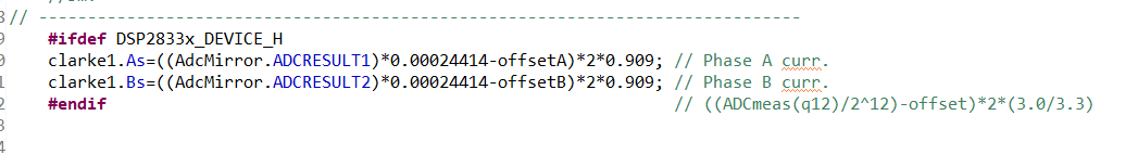
With TI provide sensor less FOC control code, inside the code of current ADC function taken reading of ADCRESULT 1 AND 2 for phase current a, b.(See pic 1) But in the provided hardware diagram shows the phase current was not using ADC 1, 2 as current feedback. (See pic 2). I had searched and read through the ADC library but quite confuse on the sequence method they state. Anyone can tell where is this ADCRESULT 1 and ADCRESULT 2 taken from which ADC?
2. Voltage feedback circuit
With the function of sensorless FOC control, why the diagram shows phase voltage measurement? The macro of Phase voltage calculation able to calculate the phase voltages based on DC bus voltage and switching Ta,Tb,Tc. Seems this voltage feedback not used in the sample code. Are these used for optional development purpose?
Pic 1
Pic 2

