


Part Number: TMS320F28335
Hi,
Customer is using F28335 XINTF to connect FPGA for their application, to simulate external RAM.
Now they find one issue about XINTF reading. The data bit 3 (only bit 3) is wrong in this situation. What could be the issue?
1) First execute InitI2cForGpio(), then InitXintf();
2) Set/Clear the GPIO in this way: GpioDataRegs.GPBDAT.bit.GPIO32 = 0;
3) Increase the reading frequency to 20ms, the issue will happen frequently.
But, if we do in this way, there's no issue:
1) First execute InitXintf(), then InitI2cForGpio();
2) Set/Clear the GPIO in this way: GpioDataRegs.GPBCLEAR.bit.GPIO32 = 1;
3) Do NOT call InitI2cForGpio();
4) Increase the reading frequency to 20ms, the issue will NOT happen.
During the reading, we checked the registers of GPIO and XINTF, all were correct. After the wrong reading, F28335 can still write the right value to external RAM, and then can read the right value back. But, several times later, wrong bit 3 will be read again.
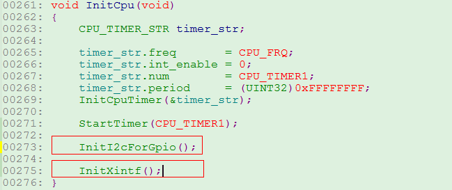

And the XINTF init code is as:
static void InitXintfGpio(void)
{
EALLOW;
GPIO_2_OFF;
GpioCtrlRegs.GPCMUX1.bit.GPIO64 = 3; // XD15
GpioCtrlRegs.GPCMUX1.bit.GPIO65 = 3; // XD14
GpioCtrlRegs.GPCMUX1.bit.GPIO66 = 3; // XD13
GpioCtrlRegs.GPCMUX1.bit.GPIO67 = 3; // XD12
GpioCtrlRegs.GPCMUX1.bit.GPIO68 = 3; // XD11
GpioCtrlRegs.GPCMUX1.bit.GPIO69 = 3; // XD10
GpioCtrlRegs.GPCMUX1.bit.GPIO70 = 3; // XD19
GpioCtrlRegs.GPCMUX1.bit.GPIO71 = 3; // XD8
GpioCtrlRegs.GPCMUX1.bit.GPIO72 = 3; // XD7
GpioCtrlRegs.GPCMUX1.bit.GPIO73 = 3; // XD6
GpioCtrlRegs.GPCMUX1.bit.GPIO74 = 3; // XD5
GpioCtrlRegs.GPCMUX1.bit.GPIO75 = 3; // XD4
GpioCtrlRegs.GPCMUX1.bit.GPIO76 = 3; // XD3
GpioCtrlRegs.GPCMUX1.bit.GPIO77 = 3; // XD2
GpioCtrlRegs.GPCMUX1.bit.GPIO78 = 3; // XD1
GpioCtrlRegs.GPCMUX1.bit.GPIO79 = 3; // XD0
GpioCtrlRegs.GPBMUX1.bit.GPIO40 = 3; // XA0/XWE1n
GpioCtrlRegs.GPBMUX1.bit.GPIO41 = 3; // XA1
GpioCtrlRegs.GPBMUX1.bit.GPIO42 = 3; // XA2
GpioCtrlRegs.GPBMUX1.bit.GPIO43 = 3; // XA3
GpioCtrlRegs.GPBMUX1.bit.GPIO44 = 3; // XA4
GpioCtrlRegs.GPBMUX1.bit.GPIO45 = 3; // XA5
GpioCtrlRegs.GPBMUX1.bit.GPIO46 = 3; // XA6
GpioCtrlRegs.GPBMUX1.bit.GPIO47 = 3; // XA7
GpioCtrlRegs.GPCMUX2.bit.GPIO80 = 3; // XA8
GpioCtrlRegs.GPCMUX2.bit.GPIO81 = 3; // XA9
GpioCtrlRegs.GPCMUX2.bit.GPIO82 = 3; // XA10
GpioCtrlRegs.GPCMUX2.bit.GPIO83 = 3; // XA11
GpioCtrlRegs.GPCMUX2.bit.GPIO84 = 3; // XA12
GpioCtrlRegs.GPCMUX2.bit.GPIO85 = 3; // XA13
GpioCtrlRegs.GPCMUX2.bit.GPIO86 = 3; // XA14
GpioCtrlRegs.GPCMUX2.bit.GPIO87 = 3; // XA15
GpioCtrlRegs.GPBMUX1.bit.GPIO39 = 3; // XA16
GpioCtrlRegs.GPAMUX2.bit.GPIO31 = 3; // XA17
GpioCtrlRegs.GPAMUX2.bit.GPIO30 = 3; // XA18
//GpioCtrlRegs.GPAMUX2.bit.GPIO29 = 3; // XA19
GpioCtrlRegs.GPBMUX1.bit.GPIO34 = 3; // XREADY
GpioCtrlRegs.GPBMUX1.bit.GPIO35 = 3; // XRNW
GpioCtrlRegs.GPBMUX1.bit.GPIO38 = 3; // XWE0
//GpioCtrlRegs.GPBMUX1.bit.GPIO36 = 3; // XZCS0
GpioCtrlRegs.GPBMUX1.bit.GPIO37 = 3; // XZCS7
GpioCtrlRegs.GPAMUX2.bit.GPIO28 = 3; // XZCS6
GPIO_2_ON;
EDIS;
}
Thanks a lot.
Br, Jordan


