


Part Number: TIDM-HV-1PH-DCAC
In the baseboard schematics-
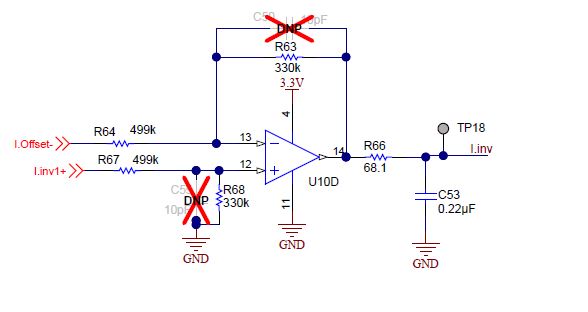
I.inv is the AC sensed current output. I'm unable to understand that in the controller card connector why so many pins are connected to I.inv in the schematic.

Regards,
Archit.
Part Number: TIDM-HV-1PH-DCAC
In the baseboard schematics-
I.inv is the AC sensed current output. I'm unable to understand that in the controller card connector why so many pins are connected to I.inv in the schematic.
Regards,
Archit.


