This thread has been locked.

If you have a related question, please click the "Ask a related question" button in the top right corner. The newly created question will be automatically linked to this question.

TMS320F280049: TMS320F280049

Part Number: TMS320F280049


Hi Experts,

Customer wonders if the ADC sampling hardware need to be optimized, for example reducing R741 & R743 value, because there is abnormal phenomenon happening in the below situation.

As the below picture shown, the two sampling circuits with same structure and components, when put 12V DC source to both VBAT_1 and KL_15,

1) Connected the VBAT_AD & KL15_AD pin with MCU, one ADCResult is 1210, while another is 1224, the value of VBAT_AD & KL15_AD corresponds to related ADCResults value, however the actual ADCResults value has a big gap compared with the ideal result value 1241.

2) When disconnect the VBAT_AD & KL15_AD pin with MCU, the VBAT_AD & KL15_AD voltage is correct.

3) As for customer’s requirement, the error of VBAT_1 and KL_15 calculated value by ADCResult should be limited to 0.2V, reflected to ADCResult error is 21 LSB.

Could you please provide some suggestion on this issue, thanks!

ADC sampling circuits
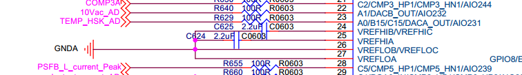
Pin map diagram

- Rayna Wang

  • Hi Rayna,

    The equivalent source impedance consisting of voltage divider R741/R737 and series resistance R719 and filter cap C641 is way too high and will cause incorrect sampling since the calculated sampling time for the circuit is too large.  This is true for both circuits.  To illustrate, let us take the first circuit and using the guidelines TRM section 13.3.2 (Choosing an Acquisition Window Duration), simplify the circuit so we can use the formula for sample and hold times in that section.  Below is the original and the simplified circuit:

    Using the formula in section13.3.2, we have the following:

             T = (RS + Ron)*CH + RS*(CS+Cp)

            T= (47.84k + 500)*12.5pF + (47.84k)*(1nF + 9.2pF) = 48.9uS (overall equivalent RC time constant of the entire circuit)


            k = ln(2n / settling error) – ln((CS + Cp)/CH); let settling error be 0.25LSB

            k = ln (4096/0.25) – ln((1nF+9.2pF)/12.5pF) = 5.313 time constants needed to settle the value to within 0.25LSB


            solving for SH (sample and hold):


            SH = k*T = 48.9uS*5.313 = 260uS

    As can be seen from the calculations, the required sample and hold time for the current circuit is way too high.  Typical SH times should be less than 1uS.  To attain this, try reducing the voltage divider resistance, series resistance and the input filter capacitance to lower the SH requirement.  This is one option.  If reduction of the resistance and capacitance values is not an option, you need to buffer the voltage divider circuit before feeding the signal to the ADC input of the TMS320F280049 device.

    Let me know if you have additional questions on this topic.

    Regards,

    Joseph


  • Hi Joseph,

    Thank you for so detailed analysis. Customer will change their circuit as you suggested.

    Regards
    Rayna
  • Hi Rayna,

    Let me know if customer still has an issue with accuracy after changing resistor and cap values to meet their ACQPS (sample and hold) and conversion accuracy requirements.  Please point the customer to section 13.3.2 (Choosing an Acquisition Window Duration) of the TRM to guide them in choosing values for their voltage divider and input capacitance.

    In the meantime, I am marking this thread as resolved.

    Best regards,

    Joseph