This thread has been locked.

If you have a related question, please click the "Ask a related question" button in the top right corner. The newly created question will be automatically linked to this question.

CCS/TMS320F28035: Issue with clock output terminal signal in experimental kit

Part Number: TMS320F28035
Other Parts Discussed in Thread: C2000WARE

Tool/software: Code Composer Studio

Hi

I am using the expermimenter kit for the TMS320F28035 microcontroller. I need verify the maximum work frecuency and check the performance of my software routine, so in the file Gpio.c, I seted the 18 pin to see the clock. But when I connect the osciloscope probe to de 18 pin the ePWM outputs changes therefore I lost the control of my circuit. Now If I remove the osciloscope probe from the 18 pin the ePWM outputs again is correct.

  • S.Ibarra,

    1. Are you using the internal oscillator or an external clock source?
    2. Can you verify that the voltage on the 3V3 supply with and without the probe connected?
    3. What are your settings for XCLKOUTDIV register?
    4. How much does your PWM output change.
      1. Does the frequency change
      2. Does the duty change? 

    Does your code change the PWM output, could it be that connecting this probe is causing bad inputs that result in your controller changing the PWM output?

    Regards,
    Cody 

  • Hi, Cody

    1. I´m using the internal oscillator.
    2. The 3V3 supply change whit the probe connected. It´s like if the clock signal superposed at the supply signal.
    3. The XCLK registers is set to XCLK.all = 0x0042.
    4. The PWM´s changes are in frecuency and duty cicle, this signal dos not correspond to my control subrutine.
    5. My control subrutine it is in open loop, does not depend, in this moment, of any input signal.

    Thank you very much

    Sebastian
  • Sebastian,

    1. Can you provide an image to show what the 3V3 supply looks like with and without the probe?
    2. Does the frequency change by a fixed amount? Maybe by a fixed percentage?
    3. Do you have any external hardware connected to the device? If so, please remove it while testing.
    4. Could you try running a basic PWM example from C2000Ware, enable XCLKOUT and see if you can still see the same behaviour when you attach a scope probe?
    5. If you connect the scope probe to another device pin do you see the same problem?
    6. If you disable XCLKOUT, does the problem go away?

    Thanks,
    Cody

  • Hi, Cody


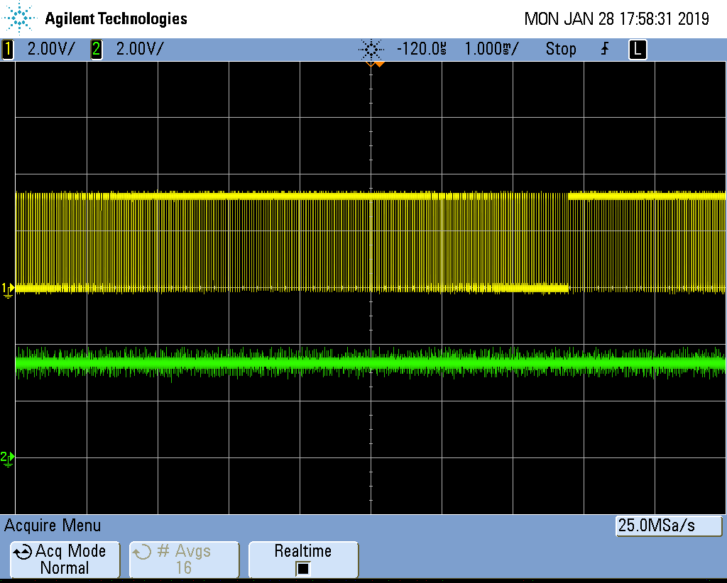
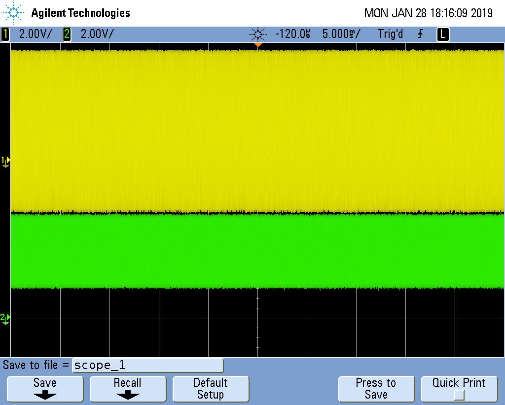
    1. I send two images: (scope_0.png) with probe 2 connected to the 3V3 source and the probe 1 connected to the epwm output. (scope_1.bmp) with probe 2 connected to the 3V3 source and probe 1 connected to Xclockout (pin 18).
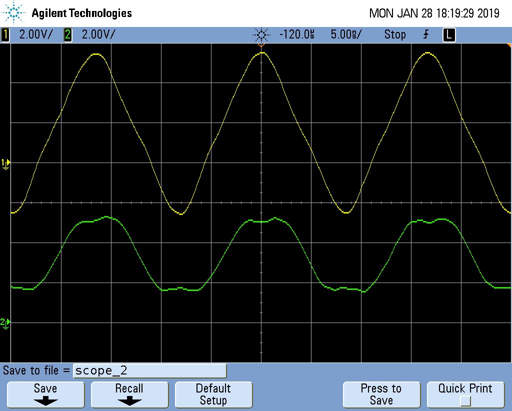
    2. Responding to the question two, I send a zoom image (scope_2.bmp) that correspond with scope_1.bmp.
    3. I don´t have any external hardware to the experimeter kit.
    5. I checked with all (except pin 18) pins of experimenter kit and don´t appear the fenomena.
    6. Whe I disable the Xclockout signal don´t appear the fenomena.
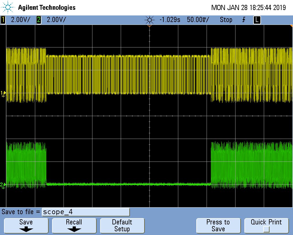
    7. I include the image (scope_4.bmp) that show the epmw output and xclockout signal. The changes correspond with connection and disconnection of osciloscope probe at the xclockout (pin18)

    Sebastián

  • Sebastian,

    1. can you show me where you are measuring the 3V3 supply on the experimenters kit? 
    2. Are you using a special kind of oscilloscope probe? It looks like you are coupling massive amounts of noise through the scope.
    3. Does the device continue to operate normally with the 3V3 oscillating like that?
      1. It looks like this may be an oscilloscope issue not a HW issue. 
    4. Can you check if the noise is coupled through the scope? If you have two oscilloscopes connect one to XCLKOUT and the other to 3V3. Is the noise still coupled?


    Regards,
    Cody 

  • Hi Cody

    1. I´m connecting the osciloscope probe in the pin´s that are behind of external voltage source conector (JP1) in experimeter kit. 

    2. I´m using a DSO5032A Agilent Osciloscope with the standard probes (Agilent N2863A).
    3. The experimenter kit and the microcontroller continues operation, I belive that correctly.
    4. I think that you have reason with respect to noise coupling. I will verify this.

    Using this communication I want to question the following.
    I can use the experimenter kit at 60 MHz ?, because in the present configuration of clock and epwm´s my main program is very slow.

    Thank you very much


    Regards


    Sebastián

  • Sebastián,

    great, let me know what you find.

    To answer your question F28035 is designed to run at 60MHz. So yes, you can change the clock configuration to run at 60MHz.

    Regards,
    Cody 

  • Have you found the source of this noise? The thread will be closing soon due to inactivity.

    Cody