This thread has been locked.

If you have a related question, please click the "Ask a related question" button in the top right corner. The newly created question will be automatically linked to this question.

TMS320LF2407A: TMS320LF2407APGEA

Part Number: TMS320LF2407A

Abnormal description:
After the MCU's burning and writing program, after the factory has passed the test according to the standard of the whole converter, it will leave the factory to the client. When the converter is on power, it will not be displayed and the converter will be returned to the factory for testing.
[1] The supply voltage of each group was normal.
[2] The oscillation waveform and frequency of crystal oscillator are normal.
[3] The output level of MCU external reset IC is high and normal.
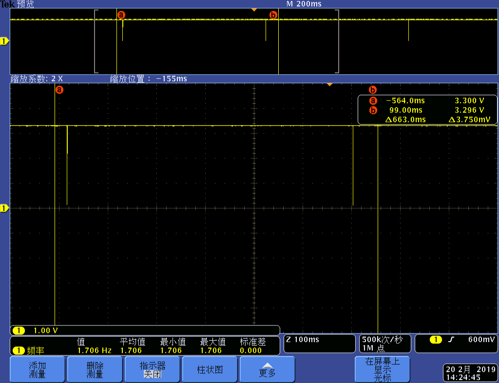
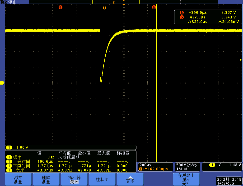
[4] Test the abnormal RS waveform of MCU PIN-133 pin, the waveform is as follows:

  • I am unable to see the images in your post. Could you please re-post them?

    Here is what I understood of the problem:
    The product passes all the testing done before shipping to the customer, but the product fails at the customer.

    How long has this product been in production?
    How many units have been returned to the factory with this symptom?
  • Customers have been producing this product for 10 years, and similar problems have been reported to customers before (4-5 PCS). This phenomenon can be eliminated by downloading the program again. Now customers want to find out the reason. Now customers have only one machine on hand to keep this phenomenon.

  • So, the issue is resolved by re-programming the flash memory? Assuming there is a hardware issue, I don’t understand how it gets resolved by reprogramming the device.

    The waveform you see on the -RS pin is abnormal and doesn’t look like it is initiated by the watchdog. Is the WD disabled by the code? Is the waveform captured at the test-point (RS-DRIVE) or at pin 133 itself?

    On a different note, I am curious about the function of R85 & R86. Since they are both 10K, all that voltage divider does is to present 1.65v to pin 33, which is neither logic high nor low.
  • So, the issue is resolved by re-programming the flash memory?
    ---—— YES
    Assuming there is a hardware issue, I don’t understand how it gets resolved by reprogramming the device.
    hardware issue
    -------I agree that this is not a hardware issue.

    The waveform you see on the -RS pin is abnormal and doesn’t look like it is initiated by the watchdog.
    ——————I suspect it was caused by the watchdog.Later, I will ask the customer to grab the waveform with a logic analyzer to see if the pulse width is 128 CLKIN cycles,Possibly after February 13, 2019。

    Is the WD disabled by the code?
    -----I'll answer this question after asking the customer, Possibly after February 13, 2019

    Is the waveform captured at the test-point (RS-DRIVE) or at pin 133 itself?
    -----waveform captured at pin 133 。The waveform of test-point (RS-DRIVE)is correct.

    On a different note, I am curious about the function of R85 & R86. Since they are both 10K, all that voltage divider does is to present 1.65v to pin 33, which is neither logic high nor low.
    ------------I'll answer this question after asking the customer, Possibly after February 13, 2019
  • Can you provide the details of the circuitry connected to the VCCP pin (pin 58)?
  • The waveform you see on the -RS pin is abnormal and doesn’t look like it is initiated by the watchdog.
    ——I suspect it was caused by the watchdog.Later, I will ask the customer to grab the waveform with a logic analyzer to see if the pulse width is 128 CLKIN cycles,Possibly after February 13, 2019。

    ---I will reply you before February 21, 2019。


    Is the WD disabled by the code?
    -----I'll answer this question after asking the customer, Possibly after February 13, 2019

    -----customer Answer:WD Enable by code,


    On a different note, I am curious about the function of R85 & R86. Since they are both 10K, all that voltage divider does is to present 1.65v to pin 33, which is neither logic high nor low.
    ------------I'll answer this question after asking the customer, Possibly after February 13, 2019

    ---- customer Answer: only use R85 or R86 ,not both.

  • If those pulses are caused by the WD timing out, they would be smooth, uniform and need to go all the way to GND. Please try this: In a good board, just erase the flash and power-up the board. WD will time out and produce clean/uniform pulses that go all the way to GND. This is how the waveform should look like if WD is indeed the source of reset.

    Also, a logic analyzer is not a good choice here to capture the waveform. Please continue to use the oscilloscope.

    What tool is customer using to program the flash?
  • -----
    The waveform of -RS pint is periodic 33.5ms high-level 58us low-level. It's certain that he's WatchDog's waveform.
    I suspect that the program is incomplete.
    Now how can I read it out?

    What tool is customer using to program the flash?
    ------customer use TDS510 Program the flash.
  • I want to bring your attention to my suggestion below:
    If those pulses are caused by the WD timing out, they would be smooth, uniform and need to go all the way to GND. Please try this: In a good board, just erase the flash and power-up the board. WD will time out and produce clean/uniform pulses that go all the way to GND. This is how the waveform should look like if WD is indeed the source of reset.


    Please refer to Table 11-3 in page 11-11 in SPRU357B. That shows how to calculate the WD timeout frequency. Does the observed timeout match with the calculated timeout according to that table?

    If you suspect the flash did not get programmed properly the first time, you need to connect the device to CCS, dump the flash contents and compare it with the file that was programmed. If there is a problem in the flash programming setup, I would expect every device to have the problem.
  • The waveform of watchdog action on the good board:

  • This is how a “clean” WD reset pulse should like. But the waveform from the suspect board did not look like this.

    You have not responded to my queries below:
    Please refer to Table 11-3 in page 11-11 in SPRU357B. That shows how to calculate the WD timeout frequency. Does the observed timeout match with the calculated timeout according to that table?


    If you suspect the flash did not get programmed properly the first time, you need to connect the device to CCS, dump the flash contents and compare it with the file that was programmed. If there is a problem in the flash programming setup, I would expect every device to have the problem.
  • Kevin – I haven’t heard back from you, I’m assuming you were able to resolve your issue. If not, just post a reply below.
  • hareesh:

    The customer reads the code of the chip on the exception board. The data of 0X0000-0X3FFF is 0x0000, 0X4000-0X7FFF is 0xffff.
    Customers say there is no use of write code space in the software.
  • So, this board passed all the production tests before shipping to customer, but came back with corrupted flash data as illustrated in your previous post? What happens if you try to reprogram the flash with the correct code? Does the product start working again?

  • Also, please clarify how long the current flash programming method has been in use. Was anything changed in the recent past?
  • If the rewriting program can work properly, it used to be handled in the case of abnormalities. Now customer want to find out the reason.

    the current flash programming method 

  • Sorry, I don’t understand your response. I need answers for each one of the following questions:

    1. So, this board passed all the production tests before shipping to customer, but came back with corrupted flash data as illustrated in your previous post?
    2. What happens if you try to reprogram the flash with the correct code? Does the product start working again?
    3. How long the current flash programming method has been in use?
    4. What software tool is used to program the flash?
    5. Was anything changed in the recent past?
    1. So, this board passed all the production tests before shipping to customer, but came back with corrupted flash data as illustrated in your previous post?YES
    2. What happens if you try to reprogram the flash with the correct code? Does the product start working again?

      Previous abnormal boards solved this problem by rewriting the program.

      Now this abnormal board is still in the hands of the customer, he is planning to re-write the program, and I will give you feedback as a result.

    3. How long the current flash programming method has been in use? At least five years
    4. What software tool is used to program the flash? Using TDS510 to burn through JTAG interface
    5. Was anything changed in the recent past?  NO
  • For Q4, TDS510 is the H/W. What software tool is used? Is it the flash plug-in that is part of CCS3.3? Or is it some other utility like SDFlash that uses TDS510?
  • Kevin,
    Please update on the status. This issue has been open for too long. Would like to drive it to closure.