This thread has been locked.

If you have a related question, please click the "Ask a related question" button in the top right corner. The newly created question will be automatically linked to this question.

TMS320F28069M: one Phase sPWM in H-Bridge using F28069M

Part Number: TMS320F28069M


Hi all:

Thanks for helping me in Advance. im now working on TAPAS Board with F28069M for my graduation work. I wanna to achieve the sPWM Output in the H-Bridge, which ist by 2 Half Bridge combined.

The Version of Matlab is 2018b and CCS 8.2.0.  On the Board ePWM4A and ePWM4B Control two FETs separately on Half-Bridge. and then i will use ePWM4A/B and ePWM5A/B to realise the H-Bridge. At the 2 Outputs of 2 channels i linked a resistor in order to measure the Output voltage. the frequency of PWM i set is 10kHz. The Synchronization of 2 ePWM Blocks is also set. In Addition i didn't use the Deadband for each block.

I have already tried it so many times but unfortunately it didnt work. there is Always noise when i download the model to the board, i thought it was short circuited. how can i set the Parameters in the blocks correctly?

Thanks so much if you can give me the answers as soon as possible, i will appreciate it. 

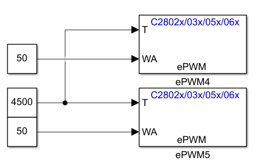
 below are the configuration of ePWM blocks. Here is the Model i tried

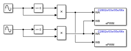
The Phase of second "Sine Wave" is delayed pi rad in order to realise the invertede Sine Wave, and the sample time i set is 1e-5, although i think 1e-4 is already enough.

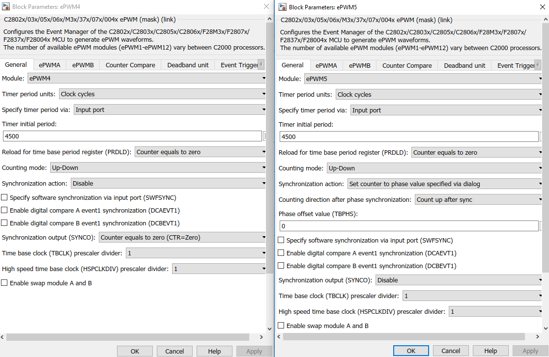
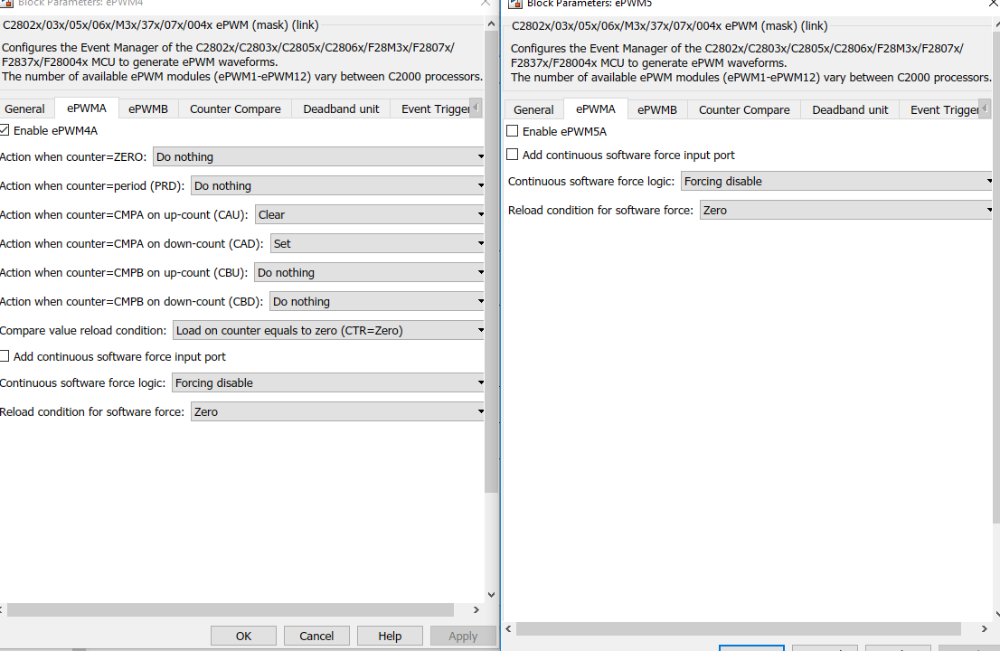
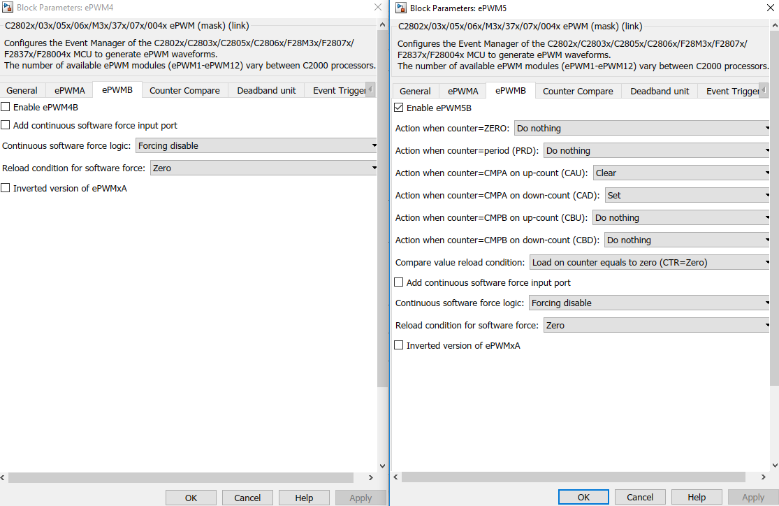
The configuration of wPWMs.

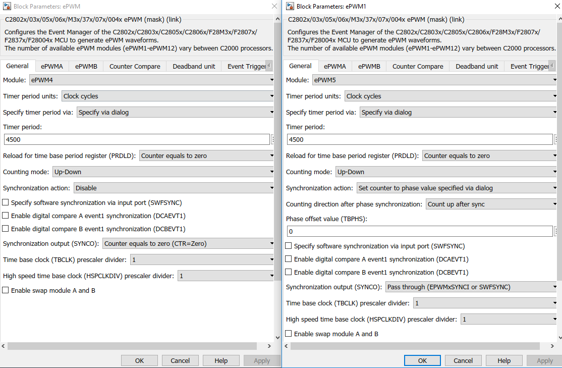
ePWM4A and ePWM5A for the Control of above MOSFET in 2 Half-Bridge.

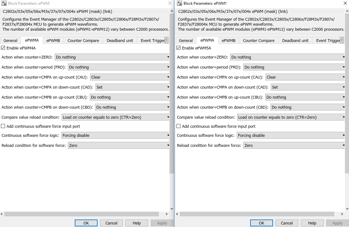
ePWM4B and ePWM5B for the Control of 2 below MOSFET in 2 Half-Bridge.

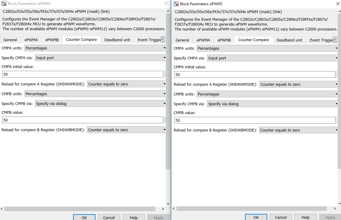
and the "Counter Compare"

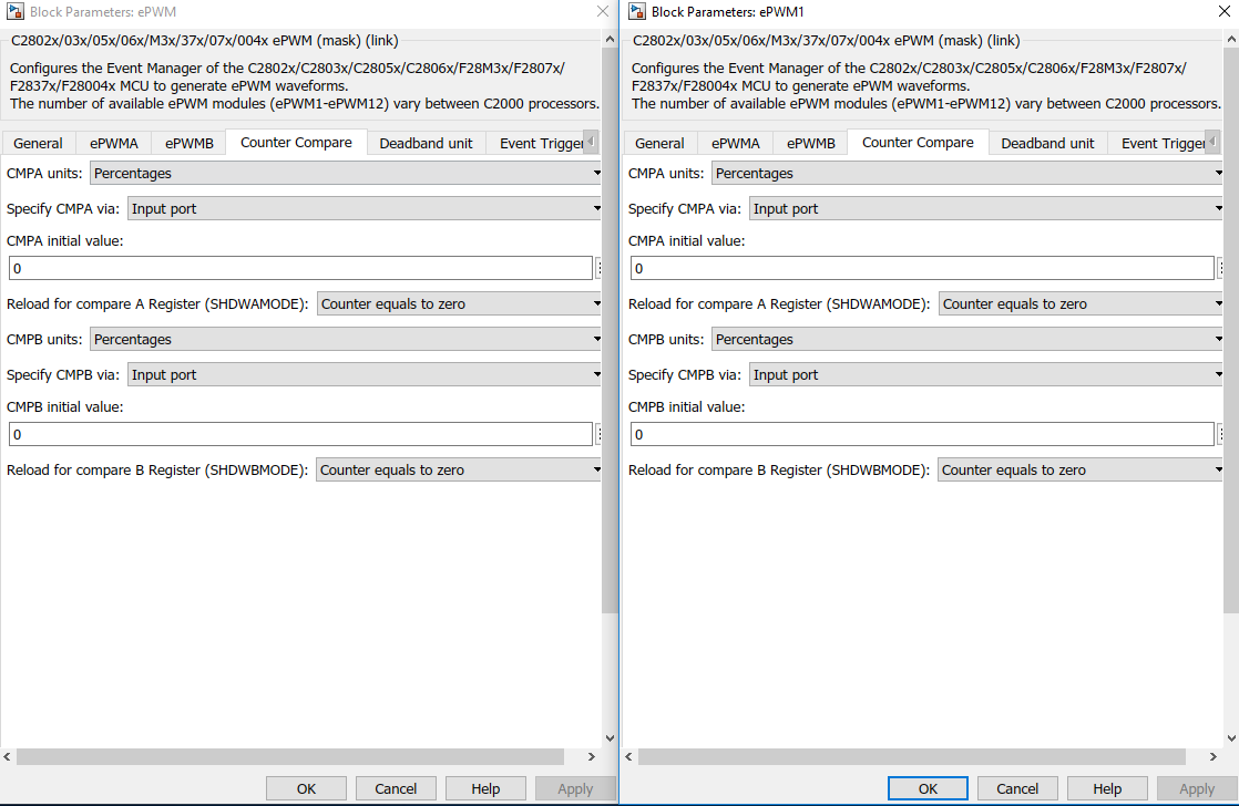
Please tell me how to use the ePWM Block in order to achieve the sPWM in H-Bridge.

Thank you all so much.

Yansong

  • Yansong,
    I may be able to help if you provide some more details on what is happening. What do you mean when you say there is noise when the model is downloaded?

    I would suggest that you do not connect this to any high power circuitry until you have verified the PWM output.

    You will need some sort of dead band whether you use the Dead-Band sub module or if you adjust your CMPx values to account for the dead band.

    Regards,
    Cody
  • Hi,

    This is application specific question. As Cody suggested, you may want to first ensure the output at the ePWM and see if that is consistent.
    Please use sine type as sample based over time based and see if that makes any difference.
  • Hi Cody,

    Thanks for your Reply. The noise after download the model(code) i thought from MOSFETs, the circuit was short circut as the below picture shows. if i didn't push the "Reset" buttom on the board, the board will be Burnout, and must new board to use.

    And now i used just 20V as power circuitry. As you said, i have already enabled the Deadband, but it can't realise the function of sPWM in H-Bridge.

    So i test the 2 Half-Bridge ePWM4A/B and ePWM5A/B separately with Deadband, and 2 MOSFETS by the Control from ePWM Block operate normally.

    After i knew how to use the deadband in order to make the alternating complementary control Signals to ePWM4A and to ePWM4B. For the ePWM5A/B the Control Signal is inverted to ePWM4A/B after synchronization between 2 ePWM blocks. So the source of "RED" and "FED" for ePWM4 are both from ePWM4A, but the source of "RED" and "FED" for ePWM5 are both from ePWM5B. the reason for the choice in order to switch on and off the 4A/5B and 4B/5A in H-Bridge.


    The Parameter Adjustment of ePWM4 and ePWM5 as below Pic.

    But when i connect the OUTPUT1 and OUTPUT2 with resistor as Picture1. there is no Signal between two sides of resistor in oscilloscope. the Signal in Pic.2 cant realise, although theoretically right. so i thought Maybe the  synchronization Problem. so i connect 2 resistors seperatly between OUTPUT1 to GND and OUTPUT2 to GND in oder to see, whether the Signal PWM Output are complementary. but after test, the two Signals from OUTPUT1 and OUTPUT2 are exactly same, so it means, 4A/5A switch on and off at the same time and 4B/5B switch on and off at the same time. but they should not.

    i have already tried adjust the Control Signal to gate or a "Phase value" to delay the counter of ePWM5. but i can't figure it out, how can i realise the foundamental function of Pic 2. Is it the Problem of Synchronization? or anything else.

    Regards,

    Yansong

  • Yansong,

    Forgive me asking a basic question, but why don't you just use one PWM pair for this? Since 4A & 5B are always switched together, and likewise 4B & 5A, just remove PWM5 completely and connect PWM4 in the appropriate places.  Then your dead-band problems would go away.  

    Regards,

    Richard

  • Hi Richard,
    It's okay, i had also this thought, but it's the work i must to figure it out, and there is no negative Signal at power site. it means on the board, there is no Neutral Point to GND connected. so if i use just one Half-Bridge as Output, so i maybe can't achieve the negative part of sPWM and also i can't get the Sine Wave as output later.
    I thought it's maybe not the Dead-band Problem but the synchronization. i'm not sure.
    Thanks for your advice.
    Regards,
    Yansong
  • Hi venkatesh,
    Thanks for your Reply, i'm sure the ePWMs work Right and deadband active.
    But sine type as sample based over time based makes Nothing different. There is Always noise after download the Model.
    Regards,
    Yansong
  • Yansong,

    Will you make the change that Richard suggested and remove the unneeded PWMs?

    Can you provide a oscilloscope capture of the 4 PWM signals when there is no load connected? I would like to see the dead-band between these signals.

    Regards,
    Cody
  • Hi Cody,

    Thanks for your help. I have already figured it out. I used 2 Half-Bridges to combine one H-Bridge (4 ePWM and 5 ePWM). It's worked.

    Regards,

    Yansong