This thread has been locked.
If you have a related question, please click the "Ask a related question" button in the top right corner. The newly created question will be automatically linked to this question.
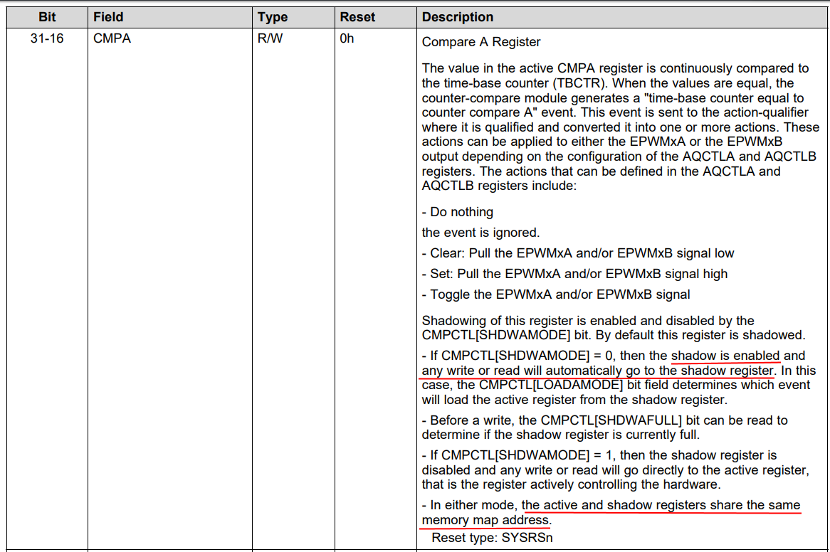
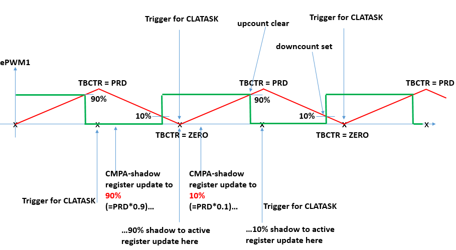
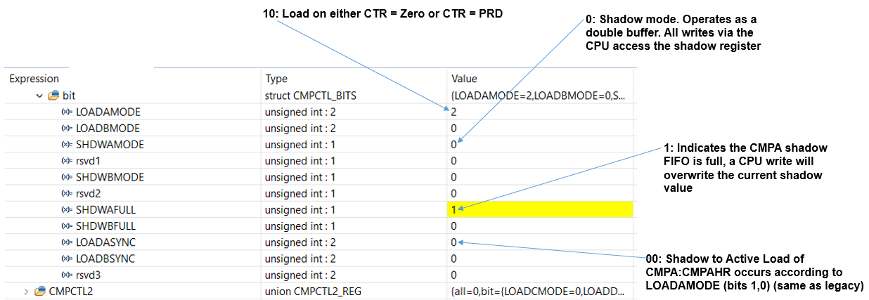
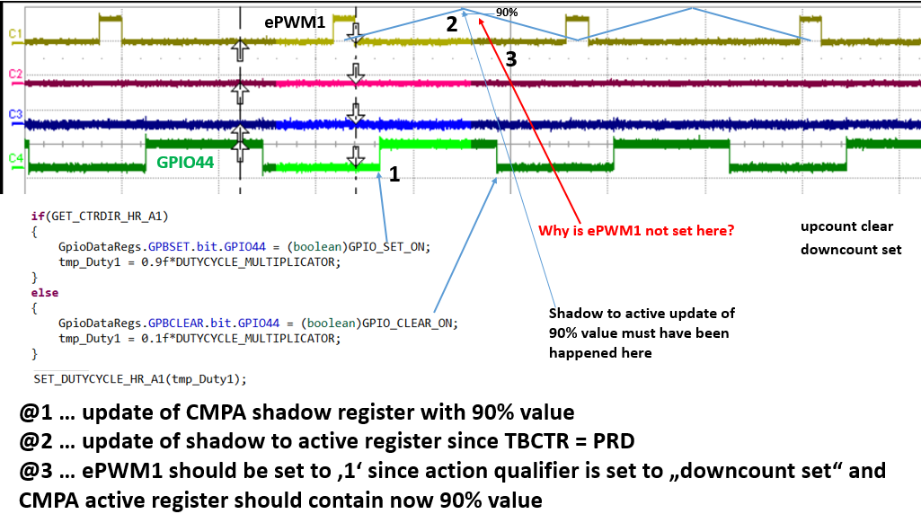
I am using a PWM in up-downcount mode which I want to update with different CMPA-values at both TBCTR = 0 and TBCTR = PRD. So the CMPA-value changes twice per PWM-period. LOADAMODE register is set to "10" which corresponds to "load on either CTR = Zero or CTR = PRD". SHDWAMODE ist set to 0 -> shadow mode, and LOADASYNC is set to 0, that means that shadow to active load of CMPA occurs according to LOADAMODE.
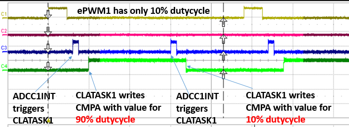
However, although I can see, that the CMPA register toggles between a high value and a low value (since I write at two different occasions per period two distinct values into the CMPA-register), the PWM indicates clearly that only one CMPA-value is taken for the comparison with the time base counter. The behaviour of the PWM is as if a shadow to active register load is done only once and not twice per period. WIth period I mean a full upcount and downcount cycle. LOADAMODE = 0 and LOADAMODE = 1 and LOADAMODE = 2 produce the same PWM.
I tried an immediate update, and there the system behaves as expected. With immediate update I get the PWM I would expect to get with shadow update at TBCTR = 0 or TBCTR = PRD.
The system I am using is entirely deterministic, thus the update of the CMPA value is done exactly at the same time with respect to the time base counter, in fact the update is triggered when the time base counter is zero and when the time base counter equals PRD.
Any ideas what goes wrong here?
Hi Sieghard,
So to summarize the desired behavior:
And you have
As best I can tell, that should be sufficient.
Some potential avenues for debug:
Hi Devin,
thank you for your help.
Please see my replies to your remarks:
Yes, in fact it is "up count clear"
Yes, this is "down count set"
This is what I want, and I also see that the CMPA-register must have been updated, but I am not sure, that this takes place at ePWM = PRD.
Exactly: The ISR is executed, and the CLA writes the CMPA-register. I am positive, that this value is written, since I can see it with the debugger in the CMPA register. The CLA writes the value decimal 60 into the CMPA register.
Yes, this is my intention, but also I am not sure, that this really takes place at ePWM = ZERO
Yes. I can see, that this ISR is also executed. The same CLA writes the decimal value 1140 into the CMPA register. So the CMPA register toggles between the values 60 and 1140. Two distinct values, which should result in the corresponding ePWM. However, the ePWM is the one you will get with a CMPA-value of decimal 60.
What I see is, that the SHDWAFULL bit toggles between 0 an 1. This indicates that the shadow FIFO is full. But I cannot see how this could happen. Both ISR are executed, both CMPA-values can be seen in the CMPA register. I can see the moment when the update to the CMPA register takes place, by toggeling a GPIO, and this is definitely twice per ePWM period. Both moments are separated by PRD/2.
And you have
Yes it is.
Well the debugger sometimes does not display the correct values, but when I take a look at the corresponding addresses (view memory at address), I can see that the registers are configured with the expected values. So i am sure that the registers are configured correctly
Definitely. Both ISR are executed. Both values are written into the CMPA register.
Yes it must be. I would get a CLA-overflow if this is not the case. However the SHDWAFULL bit toggles, but this can only be the case, when I overwrite the CMPA-shadow value. Is this correct?
Yes it toggles between 60 and 1140. My time base period value is 1200, and as far as I can see the CMPA-register has only the values 60 and 1140.
I have also created a scope screenshot, where the timing can be seen. It should result in a ePWM1 signal that has for one half of the period a 10% dutycycle and for the other half of the period a 90% dutycycle. But what I get is an ePWM-signal with 10% dutycycle as though only one shadow to active update has happened.
Hi Sieghard,
Can you elaborate a little bit here: "Well the debugger sometimes does not display the correct values...". Do you see differences between the expressions window and the memory browser?
A couple things to note about the CMPA register. Both reads and writes (presumably including from the debugger) will go to the shadow register:
So all you can see is the shadow value, not the active value.
Furthermore, since the shadow--> active load only occurs at TBPRD or ZERO events, there should be some time where CMPA only shows you the next (shadow) value not the current (active) value. This is when SHDWAFULL bit is set. SHDWAFULL bit transitioning from 1-->0 should correspond to the shadow-->active load. When SHDWAFULL = 0, shadow CMPA = active CMPA, so you can effectively see the active value.
Hi Devin,
basically I often do not see correct values in the "Registers" window of the debugger. Even a refresh, or a continuous refresh of the registers window does not display the correct values. In this case all values of all registers are displayed as zero. It doesn't apply to any particular register, I can see this behaviour both on CPU1 and CPU2 registers. As a workaround I use the option "view memory at address", where in return I can always see the values I expect. So for me this is a display, or an update problem of the debugger which doesn't have anything to do with the problem here. I just rely more on what I see with the "view memory at address" option, than with what I see in the registers window.
I have included a screenshot:
CH1 = ePWM
CH3 = indicates when CLATASK is triggered
CH4 = indicates when the CLATASK writes the CMPA-(shadow) register
Please see also the following sketch I have made: Since I alternately update the CMPA-register with a "small" and a "high" value, I expect to get the following ePWM-signal (in green)
Did I get things right here? Is the shadow to active register update really done where I assume it's done? Another remark: I am using high resolution ePWM, thus I write both the CMPA and the CMPAHR register. According to the data sheet this is done in a single cycle.
Hi Devin,
thanks for this information. The "Expressions" window displays the correct information. I will use the "Expressions" window for future debugging sessions.
Here is a screenshot of the "Expressions" window:
For debugging purposes I will check the SHDWAFULL bit before I write the CMPA-register. Actually it should always be clear since a shadow to active load must have taken place previousely. I will let you know, as soon as I have some results.
I have just checked the state of the SHDWAFULL register: As expected, the SHDWAFULL bit is never set, when I write the CMPA:CMPAHR register. So I don't overwrite any CMPA-value.
I have included another scope plot along with the corresponding code snippet:
Hi Devin,
I don't need HR period control, I just need HR duty cycle control.
The conclusion in the thread you mentioned is, that HRCNFG[EDGMODE] has to have the same value as HRCNFG[HRLOAD]. Since I need a load on both TBCTR = ZERO and TBCTR = PRD, MEP control on both edges is not possible, because then I would have HRCNFG[EDGMODE] = 3 and HRCNFG[HRLOAD] = 2
For load on either TBCTR = ZERO or TBCTR = PRD, MEP control is only possible for falling edge. Is this correct?