Other Parts Discussed in Thread: CONTROLSUITE
Tool/software: Code Composer Studio
Hello community,
I'm going to setup an precise CPU-interupt counter to capture the elapsed time in multiples of 10 µs.
Actually I use the TMS320F28335 at a ControlCARD in R2.2, the Docking-Station USB-EMU in R3 and Code Composer Studio in the version: 6.2.0.00050 to realize my solution.
The task is to capture the time between a rising and a falling edge and calculate a time periode to set a output pin based on the same edges. The time between edges are calculated before setting the output. Cputimer0 is to capture the time in small steps. Cputimer1 is to set the output-pin and Cputimer2 contains several state-machines and other code.
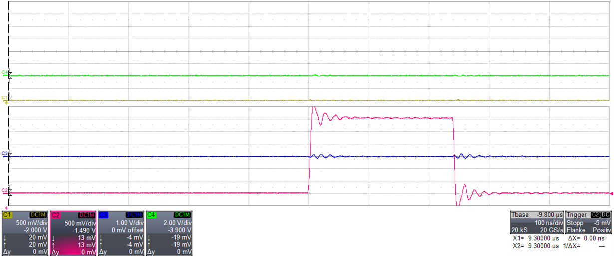
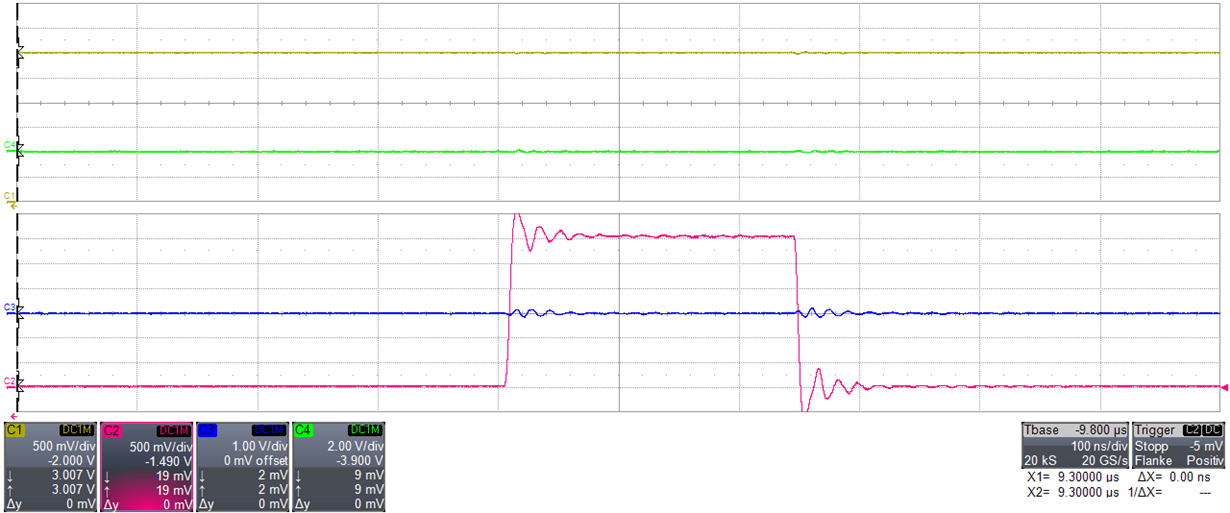
The question is: Why is there a jitter in the processing time of the cputimer0 of 45ns up to 60 ns? At the oscilloscope, with toggled output pin and only one counter (++) inside the ISR of timer 0, is the ISR activation time of the CPU-Timer0-ISR not constant.
Hint: The CPU-Frequency inside the ConfigCpuTimer()-function is aligned to improve the time capture precision and is choosen by calculation and series of measurements.
Underneath is my initialization code.
Maybe I get the chance to upload some plots of the oscilloscope, in the following days.
Thanks for your support!
Best regards,
Andreas
    Flash_CPUScaleFactor = SCALE_FACTOR;
    Flash_CallbackPtr = NULL;

	// Step 1. Initialize System Control:
	// PLL, WatchDog, enable Peripheral Clocks
	// This example function is found in the DSP2833x_SysCtrl.c file.
	InitSysCtrl();


	while(SysCtrlRegs.PLLSTS.bit.PLLLOCKS != 1) { }


	Status = Example_CsmUnlock();
	if(Status != STATUS_SUCCESS)
	{
		error();
	}


	Example_MemCopy(&Flash28_API_LoadStart, &Flash28_API_LoadEnd, &Flash28_API_RunStart);

	Example_MemCopy(&RamfuncsLoadStart, &RamfuncsLoadEnd, &RamfuncsRunStart);


	InitFlash();


	EALLOW;
	SysCtrlRegs.HISPCP.all = ADC_MODCLK;			// HSPCLK = SYSCLKOUT/ADC_MODCLK
	EDIS;

	// Step 2. Initialize GPIO:
	GPIO_SETUP();


	// Step 3. Clear all interrupts and initialize PIE vector table:
	// Disable CPU interrupts
	DINT;

	// Initialize the PIE control registers to their default state.
	// The default state is all PIE interrupts disabled and flags
	// are cleared.
	// This function is found in the DSP2833x_PieCtrl.c file.
    InitPieCtrl();

    // Disable CPU interrupts and clear all CPU interrupt flags:
    IER = 0x0000;
    IFR = 0x0000;

    // Initialize the PIE vector table with pointers to the shell Interrupt
    // Service Routines (ISR).
    // This will populate the entire table, even if the interrupt
    // is not used in this example.  This is useful for debug purposes.
    // The shell ISR routines are found in DSP2833x_DefaultIsr.c.
    // This function is found in DSP2833x_PieVect.c.
    InitPieVectTable();

    // Interrupts that are used in this example are re-mapped to
    // ISR functions found within this file.
    EALLOW;  // This is needed to write to EALLOW protected registers
    //PieVectTable.ADCINT = &adc_isr;
    PieVectTable.XINT13 = &cpu_timer1_isr;
    PieVectTable.TINT2 = &cpu_timer2_isr;

    PieVectTable.XINT3 = &IL_hyst_isr_FE;
    PieVectTable.XINT4 = &IL_hyst_isr_RE;
    PieVectTable.TINT0 = &cpu_timer0_isr;


    EDIS;    									// This is needed to disable write to EALLOW protected registers

    // Step 4. Initialize the Device Peripheral. This function can be
    //         found in DSP2833x_CpuTimers.c
    InitCpuTimers();    						// For this example, only initialize the Cpu Timers


    ConfigCpuTimer(&CpuTimer0, 149.88 , 10);

    ConfigCpuTimer(&CpuTimer1, 149.88, 10);

    ConfigCpuTimer(&CpuTimer2, 149.88, 1000);


    CpuTimer0Regs.TCR.all=0x4C00;
    CpuTimer1Regs.TCR.all = 0x4C00;
    CpuTimer2Regs.TCR.all = 0x4C00;

    // Step 5. User specific code, enable interrupts:

    // Enable CPU int1 which is connected to CPU-Timer 0/ADC-Interrupt, CPU int13
    // which is connected to CPU-Timer 1, and CPU int 14, which is connected
    // to CPU-Timer 2:

    IER |= M_INT1;
    IER |= M_INT13;
    IER |= M_INT14;


    PieCtrlRegs.PIEIER1.bit.INTx7 = 1;			// Enable TINT0 in the PIE: Group 1 interrupt 7
    IER |= M_INT12;								// Aktiveren des CPU-INT 12, welcher der zuständige für den XINT3 und XINT4 ist
    PieCtrlRegs.PIEIER12.bit.INTx1=1; 			// Freigeben des XINT3 als INT12.1 für die CPU
    PieCtrlRegs.PIEIER12.bit.INTx2=1;			// Freigeben des XINT4 als INT12.2 für die CPU
    PieCtrlRegs.PIEACK.bit.ACK12=0; 			// Freigeben des INT?!?!?! nötig?
    XIntruptRegs.XINT3CR.bit.POLARITY=0; 		//--- Auf fallende Flanke eingestellt
    XIntruptRegs.XINT3CR.bit.ENABLE=1;			// XINT3 aktivieren
    XIntruptRegs.XINT4CR.bit.POLARITY=1; 		// ext. INT4 konfigurieren, dass Reaktion bei steigender Flanke stattfindet
    XIntruptRegs.XINT4CR.bit.ENABLE=1;			// XINT4 aktivieren

    // Enable ADCINT in PIE
    // PieCtrlRegs.PIEIER1.bit.INTx6 = 1;

    // Enable global Interrupts and higher priority real-time debug events:
    EINT;   									// Enable Global interrupt INTM
    ERTM;  										// Enable Global realtime interrupt DBGM


