This thread has been locked.

If you have a related question, please click the "Ask a related question" button in the top right corner. The newly created question will be automatically linked to this question.

TMS320F28234: DSP firmware execution going errant in high-noise (EMI) environment

Part Number: TMS320F28234

I am experiencing sporadic loss of control during execution with use of a TMS320F28234 in a very noisy (EMI) power supply application. The printed circuit board for this application was designed to meet all documented TI design recommendations. In a nutshell, some of our production PCB assemblies seem to be behaving as though they are more susceptible to EMI noise than others. This design had presented relatively few problems going back to 2010 and previous. The few noise related problems that did occur in early design phase were remedied by adding filters such as ferrites to cables. In late 2017 we began to receive reports from the field of spurious fault conditions that we were eventually able to identify as EMI noise coupling into certain PCB traces. This was perplexing as the PCB itself had not been changed. We were able to get this under control by adding filter capacitors close to the DSP I/O pins that were associated with the noisy signals (where possible we also enabled digital filtering by utilization of the I/O input qualifiers). As of Q3 2018, we began to get reports of "communication failures" (which proved to be due to errant DSP program execution) from both the field and our production facility. We have tried reverting to older code versions to rule out the introduction of a bug into the firmware. We have reviewed and verified the obvious suspects such as stack overflow, unhandled interrupts, power and grounding, etc. Thus far we cannot identify a "smoking gun" to explain the behavioral changes we are observing. From our point of view the DSP seems to be more susceptible to EMI noise than experienced during the previous 7 years of combined engineering development and production. We have taken note of a TI notice indicating that a new wafer fab site was opened in Malaysia in 2016 which included production of the wafer for TMS320F28234. We see (at least superficially) a coincidence of the timing of our procurement pipeline with the emergence of this problem. Can anyone relate a similar experience?

Phil Houle - Analogic Corporation

  • Philip,

            I have not heard of any increase EMI susceptibility. I will look into this.

    Can you confirm that your PCB layout, copper thickness, and other components on the board have not changed over this same time? This could be due to a higher resistive path... Possibly even a capacitor tolerance or material change for example.

    Can you confirm that the level of EMI generated by, or induced upon, the device has remained at a constant level over this time? Maybe new EMI sources have been placed physically or electrically nearby. 

    Is this device in a case, maybe some EMI seals or grounding straps have became loose, worn, or removed for cost concerns?

    I will certainly look into this from a C2000 perspective, but I want to stress that there are a LOT of factors that can play into EMI.

    Thanks,

    Cody

  • Philip,

    a couple of follow up questions.

    1. What is the application? Is it industrial, automotive, or something else?
    2. What version of the device are using? Please provide the full OPN for example: TMS320F28234PTPQ

    Thanks,
    Cody

  • I have forwarded your questions to the design engineer for review and comment. I will send his reply ASAP.
  • The application is in the genre of medical imaging. Specifically, it is a gradient amplifier is one component of an MRI system used in clinical environments such as hospitals. Our amplifier drives the gradient coil (which surrounds the cylindrical part of the MRI “machine” in which a patient is inserted during the imaging process). This amplifier produces very high voltages and currents during a “scan” which, as you might imagine, generates copious amounts of EMI.

    The package we use is TMS320F28234PGFA.
  • Philip,

    Upon further review, EMI testing is only conducted at a system level and therefore no data is available at an IC level. No EMI failures have been reported for this device or other similar devices on this process technology. 

    C2000 does not have any production sites in Malaysia, however, the changes made around the 2016 time frame include:

    • PCN20140721003: Addition of a second source assembly site (TI Philippines) in Jul 2014
    • PCN20160412001: Addition of a second source fab site (Aizu) in Apr 2016 (non-automotive parts only)


    In either of these cases we wouldn’t anticipate any impact to system level performance (EMI or other) as they were qualified to the same datasheet parameters.

    One final note: The automotive "Q" parts have not moved production facilities, so in the interim switching to an automotive part is an option.

    Regards,
    Cody 

  • I realize that this is a very small sampling but we are tracking pass/fail results in our production facility.
    We have more units being returned from the field that we will test ASAP.

    Production failure stats (a "fail" result indicates the DSP program was confirmed to have stopped responding to test software):

    10 Wafer Code C Pass
    1 Wafer Code C Failures

    2 Wafer Code G4 Pass
    8 Wafer Code G4 Failures
  • Philip,

    Have you done any analysis as to what is causing the device to stop responding to test software?  

    This could be something as simple as noise coupled onto the XRSn line or a brown out on the device's power. If we can rule out some of the obvious suspects we may be able to get to root cause.

    Can you provide the full number shown on top of one the "C" and one of the "G4" devices?


    Thanks,
    Cody

  • Cody,

    The design engineer confirms that there has been no change to the items you mentioned (PCB layout, copper thickness, and other components on the board). Any such changes would have required his sign-off approval.

    We cannot confirm internal levels of EMI generated by, or induced upon, the device since we have never performed these measurements. The only measurement tests we perform are external to the entire rack enclosure which houses the affected assembly. The tests are done to certify compliance with generated noise and EMI levels required by the customer. We are currently looking into a means of performing internal EMI/noise measurements.

    There are no new EMI sources placed physically or electrically nearby. Our testing in production and engineering is performed in a well-controlled environment. The only nearby noise source in our test environment is a chiller used for circulating coolant within the system (which are usually located at least 10 feet away from the unit under test). The location of the chiller from the UUT has been fairly consistent over the history of the design and test of this product.

    The circuit board containing the device is in an aluminum case which, in turn, is within a custom rack. All required seals and ground straps have been inspected and approved. No changes have been made to the rack design in recent years. Some of the reported failures are coming from our production facility where we are able to perform thorough inspections for materials and workmanship. In these cases, the units are brand new (never been shipped) so wear-out is not an issue. We have built and shipped many unit from this production facility without report of this type of problem (DSP lockup).

    Phil Houle

  • Cody,

    We were able to get an debugger/emulator (Blackhawk USB2000) into the circuit experiencing the DSP lockup. We had concerns about the emulator getting overwhelmed by the noise inside the unit but it worked to our surprise. I was able to observe that the DSP program counter got set to an address outside of valid memory space which resulted inevitably in "Unhandled_ISR" which leads to a HALT of the DSP as shown.

    Halt()
    {
    asm("ESTOP0");
    while (1);
    }

    Unhandled_ISR()
    {
    Halt();
    }

    This explains the external appearance of DSP lockup but does not explain how the DSP execution got to an invalid address in the first place. We though about the XRS signal and tried adding a 1nf cap which did not prevent the lockup. We have not tried to probe the signal yet since it is difficult to discriminate actual signal noise inside the rack enclosure.

    We are trying a poor man's approach of using a gas grill spark ignitor with a few turns of wire to simulate the condition aggravating the lockup on a benchtop setup. This apparatus has been able to cause the DSP to lockup (or alternatively reset) but this has not yet proven useful due to problems with the debugger/emulator getting clobbered (the emulator reports problems with the DSP power/clock) in the process. This effect has made it impossible to get a trace when the DSP "goes off the reservation".

    We are expecting a new batch of boards tomorrow that reportedly contain devices that have been seen to lockup. Analysis of these boards may give us more information about this root cause problem.

    Regards,
    Phil Houle
  • The full numbers of the "C" and "G4" wafer devices are "CA-36C525W" and "G4A-86AX7QW".

    Device is TMS320F28234PGFA.
  • Philip,

    That great that you can run with an emulator connected!

    This may be caused by an interrupt, check your PIE vector table to get a understanding for what vectors could have sent you to the unhandled ISR. Note the vector table may hold an address a few before where the device stopped.

    Also, please check the Interrupt Flags, both the NMIFLG register as well as the PIEIFRxx registers. This will help determine if an interrupt may caused this to go "off the reservation".

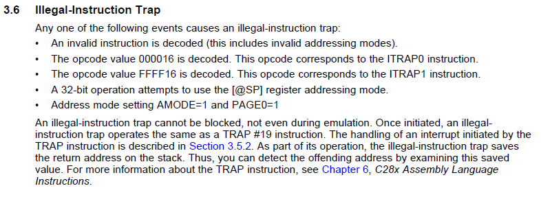
    There is one very particular interrupt that I would like you to check out... Please see the excerpt below from SPRU430

    If you did hit an Illegal-Instruction Trap then the stack will have some information on it telling us where the illegal instruction was in memory.(Note this interrupt will not indicate in the PIEIFR register)

    Do you have the ability to scope any signals on the board? Observing XRSn, VDD, VDDIO and GND could go a long way to finding resolution.

    Regards,
    Cody 

  • Phillip, 

    I just wanted to check in and see how your debug was going. Have you made any breakthroughs?

    Thanks,
    Cody

  • Cody,

    We've been trying to induce the DSP lockup (i.e. PC goes random) on a benchtop fixture by using a coil loop attached to a gas grill spark ignitor (strange but effective). The spark ignitor apparatus can easily cause the DSP to reset or lock up (as you might imagine) but also clobbers the JTAG debugger quite easily. I recently received a batch of boards from our production facility which reportedly failed due to "lockup". I was able to "cherry pick" a board which would exhibit the lockup condition while maintaining the JTAG debugger connection intact (Hooray!). I am in the process of examining the internal registers for any unexpected variances in contents. I will know more early next week as their is a lot to examine (fine tooth comb stuff). Thanks for touching base.

    Phil

  • Phil,
    Per communication from our FAE, it appears this is resolved. Could you please close this thread?