This thread has been locked.

If you have a related question, please click the "Ask a related question" button in the top right corner. The newly created question will be automatically linked to this question.

DRV8312-69M-KIT: Instaspin - Motor parameters from lab02 either too high or low?

Part Number: DRV8312-69M-KIT
Other Parts Discussed in Thread: DRV8312, MOTORWARE

So, im currently trying to setup an motor for the DRV8312 EVM kit. 

The motor im using is an Premotec BL21EE (datasheet here

When I try to run the motorware lab02b or lab02c - I either get a very high or very low USER_MOTOR_Ls_d 

I depends on the current used to identify the motor

if I use something like

#define USER_MOTOR_RES_EST_CURRENT (0.1)
#define USER_MOTOR_IND_EST_CURRENT (-0.1)

I will get the following values:

Or if I use a higher current like 0.25 - I will get way higher Lsq_H like this:
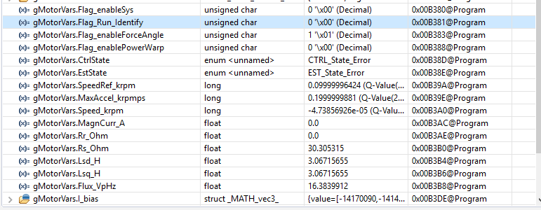
Both values will trigger either the error 

USER_ErrorCode_ctrlFreq_Hz_Low

or 

USER_ErrorCode_ctrlFreq_Hz_High 

What do I do wrong since it ends on the diffrent ends of the scale?

The motor is running during identification, and it is drawing around 0.34-0.4A from my 12V PSU. 

Is there some previous values that I should have set?

This is my motor defenition:

//! \brief USER MOTOR & ID SETTINGS
// **************************************************************************

//! \brief Define each motor with a unique name and ID number
// BLDC & SMPM motors
#define Estun_EMJ_04APB22           101
#define Anaheim_BLY172S             102
#define teknic_2310P                108
#define My_Motor					103

// IPM motors
// If user provides separate Ls-d, Ls-q
// else treat as SPM with user or identified average Ls
#define Belt_Drive_Washer_IPM       201

// ACIM motors
#define Marathon_5K33GN2A           301

//! \brief Uncomment the motor which should be included at compile
//! \brief These motor ID settings and motor parameters are then available to be used by the control system
//! \brief Once your ideal settings and parameters are identified update the motor section here so it is available in the binary code
//#define USER_MOTOR Estun_EMJ_04APB22
//#define USER_MOTOR Anaheim_BLY172S
#define USER_MOTOR My_Motor
//#define USER_MOTOR Belt_Drive_Washer_IPM
//#define USER_MOTOR Marathon_5K33GN2A
//#define USER_MOTOR teknic_2310P


#if (USER_MOTOR == Estun_EMJ_04APB22)                  // Name must match the motor #define
#define USER_MOTOR_TYPE                 MOTOR_Type_Pm  // Motor_Type_Pm (All Synchronous: BLDC, PMSM, SMPM, IPM) or Motor_Type_Induction (Asynchronous ACI)
#define USER_MOTOR_NUM_POLE_PAIRS       (4)            // PAIRS, not total poles. Used to calculate user RPM from rotor Hz only
#define USER_MOTOR_Rr                   (NULL)         // Induction motors only, else NULL
#define USER_MOTOR_Rs                   (2.303403)     // Identified phase to neutral resistance in a Y equivalent circuit (Ohms, float)
#define USER_MOTOR_Ls_d                 (0.008464367)  // For PM, Identified average stator inductance  (Henry, float)
#define USER_MOTOR_Ls_q                 (0.008464367)  // For PM, Identified average stator inductance  (Henry, float)
#define USER_MOTOR_RATED_FLUX           (0.38)         // Identified TOTAL flux linkage between the rotor and the stator (V/Hz)
#define USER_MOTOR_MAGNETIZING_CURRENT  (NULL)         // Induction motors only, else NULL
#define USER_MOTOR_RES_EST_CURRENT      (1.0)          // During Motor ID, maximum current (Amperes, float) used for Rs estimation, 10-20% rated current
#define USER_MOTOR_IND_EST_CURRENT      (-1.0)         // During Motor ID, maximum current (negative Amperes, float) used for Ls estimation, use just enough to enable rotation
#define USER_MOTOR_MAX_CURRENT          (3.82)         // CRITICAL: Used during ID and run-time, sets a limit on the maximum current command output of the provided Speed PI Controller to the Iq controller
#define USER_MOTOR_FLUX_EST_FREQ_Hz     (20.0)         // During Motor ID, maximum commanded speed (Hz, float), ~10% rated

#elif (USER_MOTOR == Anaheim_BLY172S)
#define USER_MOTOR_TYPE                 MOTOR_Type_Pm
#define USER_MOTOR_NUM_POLE_PAIRS       (4)
#define USER_MOTOR_Rr                   (NULL)
#define USER_MOTOR_Rs                   (0.4051206)
#define USER_MOTOR_Ls_d                 (0.0006398709)
#define USER_MOTOR_Ls_q                 (0.0006398709)
#define USER_MOTOR_RATED_FLUX           (0.03416464)
#define USER_MOTOR_MAGNETIZING_CURRENT  (NULL)
#define USER_MOTOR_RES_EST_CURRENT      (1.0)
#define USER_MOTOR_IND_EST_CURRENT      (-1.0)
#define USER_MOTOR_MAX_CURRENT          (5.0)
#define USER_MOTOR_FLUX_EST_FREQ_Hz     (20.0)

#define USER_MOTOR_FREQ_LOW				(10.0)			// Hz - suggested to set to 10% of rated motor frequency
#define USER_MOTOR_FREQ_HIGH			(100.0)			// Hz - suggested to set to 100% of rated motor frequency
#define USER_MOTOR_FREQ_MAX				(120.0)			// Hz - suggested to set to 120% of rated motor frequency
#define USER_MOTOR_VOLT_MIN				(3.0)			// Volt - suggested to set to 15% of rated motor voltage
#define USER_MOTOR_VOLT_MAX				(18.0)			// Volt - suggested to set to 100% of rated motor voltage

#elif (USER_MOTOR == My_Motor)
#define USER_MOTOR_TYPE                 MOTOR_Type_Pm
#define USER_MOTOR_NUM_POLE_PAIRS       (6)
#define USER_MOTOR_Rr                   (NULL)
#define USER_MOTOR_Rs                   (30.2)
#define USER_MOTOR_Ls_d                 (NULL)
#define USER_MOTOR_Ls_q                 (NULL)
#define USER_MOTOR_RATED_FLUX           (NULL)
#define USER_MOTOR_MAGNETIZING_CURRENT  (NULL)
#define USER_MOTOR_RES_EST_CURRENT      (0.1)
#define USER_MOTOR_IND_EST_CURRENT      (-0.1)
#define USER_MOTOR_MAX_CURRENT          (0.3)
#define USER_MOTOR_FLUX_EST_FREQ_Hz     (40.0)

#define USER_MOTOR_FREQ_LOW				(10.0)			// Hz - suggested to set to 10% of rated motor frequency
#define USER_MOTOR_FREQ_HIGH			(500.0)			// Hz - suggested to set to 100% of rated motor frequency
#define USER_MOTOR_FREQ_MAX				(600.0)			// Hz - suggested to set to 120% of rated motor frequency
#define USER_MOTOR_VOLT_MIN				(3.0)			// Volt - suggested to set to 15% of rated motor voltage
#define USER_MOTOR_VOLT_MAX				(12.0)			// Volt - suggested to set to 100% of rated motor voltage

  • Also note:

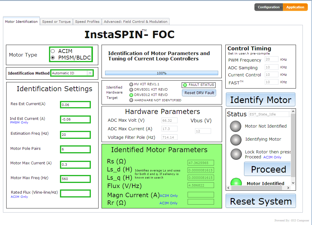
    I tried to use the auto tuner in the GUIcomposer application and got these results - which also is way off?

  • Martin,

    Do you know the voltage/current/frequency/#poles for this motor (there is no link to your datasheet).

    I'm guessing this is a very low current, high speed motor. These can be tricky to ID, but you should use lab02c (not the universal GUI), run the motor fast enough (may need to increase the _FLUX_EST_FREQ_Hz to 80.0) and inject just enough RES_EST_CURRENT to get it spinning during RampUp and keep spinning.

    There may also be a HW limitation of the DRV8312 EVM if the motor is very low voltage with a very small Bemf (which from the first image it looks like it is).

    In the end, it may not matter that much. I would guess that if you use the Rs and Flux values from your first image and set the Ls values to (0.00003) it will work pretty well without motor ID. Remember that the speed controller is not tuned, and typically for these motors the default value we provide will be too stiff. You will need to reduce the Kp at a minimum. Try a factor of 10x


    BTW - I have some posts about these types of motors on this forum from years ago. They aren't really designed to be used for FOC. They have such a large Rs and small Ls for open loop stability. Typically you can get InstaSPIN-FOC to work ok on them - at least at higher speeds - but you don't get much benefit from FOC vs. a block commutation technique (less audible noise, better dynamic performance, maybe a touch more efficiency). You will get more benefits from FOC by choosing a motor that is better designed for the application.
  • Oh, the link is dead - here it is: 

    The motor is 12 pole, running max at 5600RPM at 12V - 0.3A 

    It should be possible to make the motor run with the DRV8312 kit, since another collegue had it running with and DRV8312-C2 kit (another MCU, but same kit) - But I cant use his parameters, since it is from the "control suite" example, and not motorware, and is very diffrent. - I will try to increase RES_EST_CURRENT a bit, but during the ID, the motor is allready moving "okay" 

  • Increasing the USER_MOTOR_FLUX_EST_FREQ_Hz  to (100.0) made it run faster, and the result is more consistent, but still changing a bit - 

    Ls_q + Ls_d = 0.000960171339

    USER_MOTOR_RATED_FLUX  = 0.0103878221

    - It runs fine during the intial identification - but, after it is done identifying, when I enable it again to test the new parameters, it does run bad (jumping around, not running) 

    EDIT:

    Also, during the speed ramp up phase in the process, the gMotorVars.Speed_krpm looks OK from around 20RPM and up to the 1000RPM it will run - So it can measure the speed it is running - It just have a problem getting started when running closed loop as it tries after I enable it again after the identification. 

    EDIT #2: 

    I went ahead for lab 3A just to test something else with the new parameters - In lab 3A I get an extreme offset:

    #define I_A_offset (-8.453097522)
    #define I_B_offset (-8.430110574)
    #define I_C_offset (-8.489150584)

    As far as I can see, others get around -0.4 to -0.8 - Not -8 

    Does this indicate something is up with the hardware or still SW setup?

    EDIT #3: 

    I just tried to get lab1b working, and during step 2a, I get an output on DAC1 and DAC2, but DAC3 is just constant "High" and not changing.

    I found this thread on the forum about the GPIO for DAC3:

    Now i got DAC working for lab 1b - but it doesn't change anything in 2c

  • the offsets suggest that something might be wrong.

    make sure you are using the correct software projects for the HW you have.
    and make sure the HW switches are all set correctly

    attach the user.h in your next reply
  • Hi Chris, thanks for the help, I have attatched the User.h file -

     5734.user.h

    Im using the files found on my C:\ti\motorware\motorware_1_01_00_18\sw\solutions\instaspin_foc\boards\drv8312kit_revD\f28x\f2806xF\projects\ccs 

    I have the DRV8312EVM board + F28069X ISO control card - (Which should be the DRV8312-69M-KIT )

    The switches  on the control card is: 

    SW3 - ON ON

    SW2 - (no on label, so position HIGH or LOW) LOW LOW

    SW1 - ON ON

    on the DRV8312 EVM board:

    RSTA = MCU

    RSTB = MCU

    RSTC = MCU

    JP2 = placed

    JP1 = +12V (External PSU connected w/12V to AUX-12V)

    M1 = H

    Measuring the test point IA,IB,IC-FB and I-TOTAL, it looks like the are all biased at around 1.6-1.66V or so, and are changing with the motor running. 

    Br. Martin

    EDIT# 

    Got better offset now -0.8xxxxx.. Don't know what parameter worked for that, but that part is OK - the motor is still not identifying right - Running fine while identifying, but wont run right after identifying - 

    As far as I can read, the motor will start in open loop and then transition over to closed loop - Is there any paramters to adjust anything on that? Mabye the motor will be running fine when it is moving, but can't get out of open loop state. -

    Are there any resistors I could either replace or place another resistor in parallel to get better sensivity for the low inductance motor? My max voltage will be 12V, so I don't need the 66V range from the board, and also only drawing 0,4A, so that range could mabye also be lowered?

  • user.h
    this is incorrect. Set this to 45.0
    #define USER_PWM_FREQ_kHz (80.0)

    please keep this at 300.0
    define USER_R_OVER_L_EST_FREQ_Hz (100)


    I would increase this to (1.0) at least...
    #define USER_MOTOR_MAX_CURRENT (0.3)


    Try to ID again. What are the values? What are the offsets?

    Yes, you can change the scaling to better fit your motor. Eventually. But first just try to get this running.
  • With these settings I get:

    RS 28.9881992

    Lsd 0.00173767947

    Lsq 0.00173767947

    Flux VpHz 0.0125429649

    The motor does run a bit better with these settings - If I increase the speed to around 1.2KRPM, the motor will sometime start for around 1-2sec, but then stall again. 

    The ultimate goal is to run the motor stable at 500 RPM. 

    For the new offsets value:

    I_bias is all 3 just around -0.8455632925

    V_bias is all 3 just around 0.4889110327

    Running another time I get 

    Lsd to 0.0001672

    and

    Flux 0.01534

    with that it can run 1300-1600RPM for 10-15sec, but the feedback gMotorVars.Speed_krpm is jumping +- 400RPM, and sometimes a small spike makes it -0.6 or so

    I cant use those values again in lab 3a since I get CTRL freq low error

    ( I have implemented the fix I found in another thread with 

    if(((float_t)USER_CTRL_FREQ_Hz <= (USER_MOTOR_Rs / (USER_MOTOR_Ls_d + 1e-9) / MATH_TWO_PI)) ||
    ((float_t)USER_CTRL_FREQ_Hz <= (USER_MOTOR_Rs / (USER_MOTOR_Ls_q + 1e-9) / MATH_TWO_PI)))  )

    The motor will start spinning with IND_EST_CURRENT set to -0.02 but not run smoothly for the first second during the ramp up under open loop - from -0.03 and up it runs fine all the way during open loop 

  • I'd use these

    RS 28.9881992

    Lsd 0.00173767947

    Lsq 0.00173767947

    Flux VpHz 0.0125429649

    I think the issue you are having now is just the speed controller tuning.

    Try running lab05a which runs in torque control (no speed loop) and see if it's stable.

    If so, move on to the next labs and learn how to tune the controllers.

  • I Just tried lab 5a - The motor turn really slowly, but if i give it a little push, it will rotate constantly and stable,

    Will try to continue through the other lab5b, but I have a small problem with that 

    The motor is too weak to use the "Spring" tuning method, so I have to go with the mathmatical, but there is a few variables I can't seem to find - 

    Among other is Tau, Fs (sampling frequency), but I will try to use the day to find any stuff on the subject

    EDIT.

    I think I will start by trying to tune it using the step response in lab 5h - But I can't get it working in the speed mode since it is just jumping around instead of running

    It gives me random step responses instead

    I also had to scale USER_IQ_FULL_SCALE_CURRENT_A to (1.5) since I got an USER_ErrorCode_iqFullScaleCurrent_A_High error

  • With these variables, If it get it started by turning it manually, I can make it run and do some step measurement, but It sometimes gets stuck in some kind of mode where it will report around 4KRPM no matter what I do - the motor does nut turn, even if I manually try to help it get started. 

  • Don't change USER_IQ_FULL_SCALE_CURRENT

    set it back to the default value for the HW or it will not work correctly

    If you are getting an error on the errorCheck you may just have to comment out that code so it passes. 

    I think the errorCheck is just that the RoverL frequency (~16 KHz) is larger than your current loop frequency.

    So an option is to change the PWM frequency to (40.0), the TICK from 3 to (2.0) giving an effective 20 KHz current loop instead of 45/3 = 15 KHz. 

    Then change the values of the TICKS that are currently at (15) to (20) to give them a new effective 1 KHz rate.

    See if that clears the error.

    This is a very different type of motor with such a huge Rs relative to Ls.  This motor isn't designed for closed loop current control, it's designed for open loop stability. The HW scaling you are using is all ill designed for the motor requirements. Improving that would help.

    We may be close to what we can show with this Hardware and this particular motor.

  • Hey  - 2 quick questions.

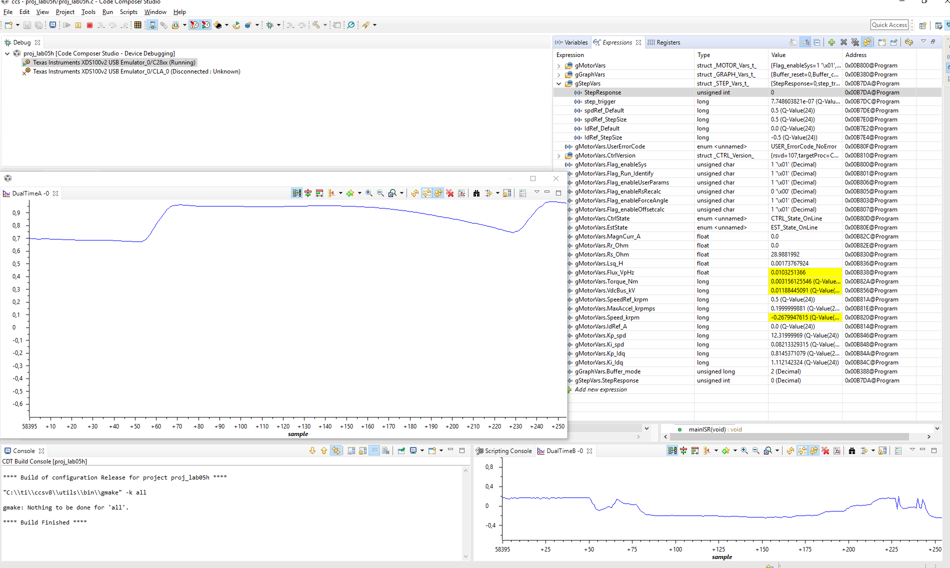
    So, I was able to tune the PID current and speed controller to have a stable step response like so:

    Anyway, I have 2 issues right now:

    1. Where do I save my newly found KI,KP, KI_SPD and KP_SPD values? Can't find room in the USER.h file. 

    2. I still have 1 issue with the motor running - The start up! - 

    I need the motor to run, I have to flick it with my finger to get it running, and If im lucky, it will "catch it" and then let it run at the ref. speed. If I dont, the motor will just vibrate a bit, and if I enable Force angle, it will move a bit back and foward, but never get up to speed - Is there anything I can calibare/adjust to get it to start by it self without my help?

    Thanks so far!


  • 1. you can't just add them to a user file. You would have to write / edit the code example.

    2. as long as you aren't limiting the output of the speed controller (by having too small of a MAX_CURRENT setting or some other method), the speed controller should continue to increase the IqRef_A of the torque controller to get the motor to start-up. 

    enabling ForceAngle isn't totally necessary, but it can be helpful in some applications.

    You should do an RsRecal before you start-up the first time though, that should help with consistent start-up.

  • Will try - I'll report back- Thanks!
  •  

    So im back at the office and have been playing around a bit - I went back and set #define USER_IQ_FULL_SCALE_CURRENT_A  to 10 (default) 

    I tried to increase t #define USER_MOTOR_MAX_CURRENT  to 5.0, but it had no impact? how much can I allow in that parameter? My motor is rated for 0.3A and it is right now 5.0A? What can else affect the speed controller regarding start up? 

    My current motor definition is:

    #elif (USER_MOTOR == My_Motor)
    #define USER_MOTOR_TYPE                 MOTOR_Type_Pm
    #define USER_MOTOR_NUM_POLE_PAIRS       (6)
    #define USER_MOTOR_Rr                   (NULL)
    #define USER_MOTOR_Rs                   (29.8624153)
    #define USER_MOTOR_Ls_d                 (0.000345120265)
    #define USER_MOTOR_Ls_q                 (0.000345120265)
    #define USER_MOTOR_RATED_FLUX           (0.0110681299)
    #define USER_MOTOR_MAGNETIZING_CURRENT  (NULL)
    #define USER_MOTOR_RES_EST_CURRENT      (0.07)
    #define USER_MOTOR_IND_EST_CURRENT      (-0.07)
    #define USER_MOTOR_MAX_CURRENT          (5.0)
    #define USER_MOTOR_FLUX_EST_FREQ_Hz     (100.0)
    
    #define USER_MOTOR_FREQ_LOW				(50.0)			// Hz - suggested to set to 10% of rated motor frequency
    #define USER_MOTOR_FREQ_HIGH			        (560.0)			// Hz - suggested to set to 100% of rated motor frequency
    #define USER_MOTOR_FREQ_MAX				(670.0)			// Hz - suggested to set to 120% of rated motor frequency
    #define USER_MOTOR_VOLT_MIN				(1.8)			// Volt - suggested to set to 15% of rated motor voltage
    #define USER_MOTOR_VOLT_MAX				(12.0)			// Volt - suggested to set to 100% of rated motor voltage

    My KI_Idq is 1.5 and KP_Idq 3.5 - for the speed controller:

    KP_spd = 0.0539

    KI_spd = 0.00011992 (can't increase any of these 2 values without getting abnormal step response with peaks in it) 

    My step response for speed looks like this:

    Just before it increases the speed, the RPM drops - Does that indicate something like getting too little current?

    another thing I have been thinking about - My RS is pretty steady around 29-30 (Ohm I pressume) - On the datasheet for my motor, it says 39Ohm from phase to phase, so 19,5Ohm from phase to GND - Is there anything I should do to change this? 

  • I'd increase

    USER_MOTOR_RES_EST_CURRENT      (0.2)

    to see if the Rs value ID'd changes


    there is no issue with this setting. This doesn't command anything, it just limits the max IqRef_A command. That isn't what the motor will actually draw.

    USER_MOTOR_MAX_CURRENT          (5.0)


    use a multi-meter across 2 phases to measure Rs. Divide by 2 and this should be the value you use in user.h


    having an incorrect Rs value (especially a value higher than the actual Rs) will make start-up behave poorly. So investigate this area.


  • the (measured with multimeter) resistance between 2 phases is 42.8Ohm, so the measurement from the DRV8312 kit should give me around 21.4Ohm, but is always giving me a value between 28-30Ohms - I have tried with USER_MOTOR_RES_EST_CURRENT from 0.03 (10% of rated current) and up to 0.3 (100% current) - All gave me around the same result - If I go lower than 0.03, I get like 3000 Ohms, and the motor does not spin. 

    Manually entering 21.4Ohm made lab 5h run a bit "smoother" - It was a bit easier to tune the PID values, and the motor looks like it is trying to start a bit better - but still not starting. 

    It also seems like it does not detect the RPM's - If the motor is stalling, it will still report a value near the target RPM's, and the motor will just vibrate - But if I now just give it a little flick, the motor does start. 

    What parameter effects the Res estimation other than the current? And is there anything I can do to make it detect the RPM's better? 

    - Also, could this be a HW scaling problem? I noticed that the ADC full range voltage is 66V, and my motor will generate around 0.6V (eg. 1% of the ADC range) at 500RPM? 

    EDIT: So, I have been playing a bit around with the motor model manually, and if I set USER_MOTOR_Ls_d and q to 0.035 and keep Rs at 21.4, then the auto-estimated KP og KI values from 7h will start the motor in a few seconds - But the loop is unstable for step responses, unable to run faster than 1500 RPM. If I tune the 2 loops according to the step responses, the motor is then running stable, and have a good step response, but is unable to start up by it self. The auto estimated values for KP and KI SPD is around 1.8 and 0,006, where when I tune it, it is around 0,01 and 0,00025 

  • "- Also, could this be a HW scaling problem? I noticed that the ADC full range voltage is 66V, and my motor will generate around 0.6V (eg. 1% of the ADC range) at 500RPM? "

    Yes, as I mentioned the HW and motor combination are not a good fit. It would be better to rework the HW scaling to fit your motor better.
  • Well, after a long struggle, I found the solution / issue.

    I have a 4 lead BLDC motor (Y-configuration), and on other setups /drivers we have used, we connect the 4th wire to the 4th terminal (GND), but on the DRV8312, this is hardwired directly to GND - Disconnnecting the 4th wire, and now my motor is drawing 10% of the current it did before, and can start and run by the initial values - Also the RS is now measuring 21.4 Ohm.

    :facepalm:

    Well, Thanks for the help so far , We will try to keep on developing the system.