This thread has been locked.

If you have a related question, please click the "Ask a related question" button in the top right corner. The newly created question will be automatically linked to this question.

CCS/TMS320F28379D: DLOG Module for TMS320F28379D

Part Number: TMS320F28379D
Other Parts Discussed in Thread: C2000WARE-DIGITALPOWER-SDK, CONTROLSUITE,

Tool/software: Code Composer Studio

Hi Team,

I need to check the output using the DLOG module. I am finding the DLOG4CHC.asm for F28379D but couldn't find. 

There is DLOG4CHC.asm is avaliable for F28035 can we use that file for F28379D.???

And what changes i need to make ?? 

There is anything in which you can help ?

  • Saurabh,

    I will suggest that you use the C code version of the DLOG module located in C2000Ware-DigitalPower-SDK. This package contains the latest and improved version of the library. The source file (.c) is device agnostic and will work with the F28035. Please take a look at the API reference guide for more information on how to use the library in your application.

    Regards,
    Ozino
  • Hi Ozino,

    There is DLOG4CHC.asm is avaliable for F28035 can we use that file for F28379D.???

    and as you suggest to use the C code version of the DLOG module located in C2000Ware-DigitalPower-SDK. If I am using C:\ti\controlSUITE\libs\app_libs\digital_power\f28x7x_v1.0 paths for F28379D. Can F28379D support that ??
  • Saurabh,

    Is there a reason you would be opposed to using the C code? The C code is device agnostic. Where as the the asm file in controlSUITE may have been written specifically for a device. At that point you would be using it at your own risk.

    Regards,
    Ozino
  • Ozino,

    I am doing as per you instructed. I am using C_macros from C:\ti\controlSUITE\libs\app_libs\digital_power\f28x7x_v1.0 path.

    /**
     * Performs data logging to a specified output buffer.  This module uses DLOG_1ch_F_C structures.
     * The structure should be initialized by the DLOG_1ch_F_C_INIT macro.
     * Data logging will occur on every 'n' module call, where the logging offset must be specified
     * in the PreScalar parameter.
     */
    //================================================================================
    // Copyright (C) 2015 Texas Instruments Incorporated - http://www.ti.com/
    //  ALL RIGHTS RESERVED
    //================================================================================
    
    #ifndef DLOG_1CH_F_C_H_
    #define DLOG_1CH_F_C_H_
    
    #include "DPlib.h"
    
    /**
     * Data logger states
     */
    #define WAIT_FOR_TRIGGER ((float) 0)
    #define CHECK_FOR_RISING_EDGE ((float) 1)
    #define LOG_DATA ((float) 2)
    
    /**
     * Data logger structure
     */
    typedef struct {
    	float CurrTask;
    	float Size;
    	int16 Cnt;
    	float PreScaler;
    	float SkipCnt;
    	float Input;
    	float TrigVal;
    	volatile float *OutputBuff;
    } DLOG_1ch_F_C;
    
    /*
     * Stores data from a single Input to the buffer.
     * @param v - DLOG_1ch_F_C structure with collected data and destination buffer.
     */
    #define DLOG_1ch_F_C(v)																						\
    		if((v.CurrTask == WAIT_FOR_TRIGGER) && (v.Input < v.TrigVal)) {v.CurrTask = CHECK_FOR_RISING_EDGE;}		\
    		if((v.CurrTask == CHECK_FOR_RISING_EDGE) && (v.Input > v.TrigVal)){v.CurrTask = LOG_DATA;}				\
    		if(v.CurrTask == LOG_DATA){																				\
    			++v.SkipCnt;																						\
    			if(v.SkipCnt == v.PreScaler){																		\
    				v.SkipCnt = 0;																					\
    				v.OutputBuff[v.Cnt++] = v.Input;																\
    			}																									\
    			if(v.Cnt == v.Size){																				\
    				v.CurrTask = WAIT_FOR_TRIGGER;																	\
    				v.Cnt = 0;																						\
    				v.SkipCnt = 0;																					\
    			}																									\
    		}																										\
    		/* Ensure no invalid states */																			\
    		if(v.CurrTask > LOG_DATA) {v.CurrTask = WAIT_FOR_TRIGGER;}
    
    /**
     * Initial values for the DLOG_1ch_F_C structure.
     */
    #define DLOG_1ch_F_C_INIT(v)		\
    		v.CurrTask = 0;				\
    		v.Size = 0;					\
    		v.Cnt = 0;					\
    		v.PreScaler = 0;			\
    		v.SkipCnt = 0;				\
    		v.Input = 0;				\
    		v.TrigVal = 0;				\
    		v.OutputBuff = 0
    
    #endif /* DLOG_1CH_F_C_H_ */
    

    I am doing simple PWM interupt program in that i have use the DLOG function for channel 1 as per suggested in DPLib.

    But I am not able to get the data into the buffer.

    //!
    //! This example configures ePWM1 to produce an 2 sec
    //! waveform with independent modulation on EPWMxA and
    //! EPWMxB.
    //!
    //! The compare values CMPA modified within the ePWM's ISR.
    //!
    //! The TB counter is in up count mode for this example.
    //!
    //! View the EPWM1A(PA0_GPIO0)
    
    /*
        For Default maxSysclkout = 200 Mhz. and maxEpwmclkout = 100Mhz
    
        to change the maxEpwmclkout use  ClkCfgRegs.PERCLKDIVSEL.bit.EPWMCLKDIV = 1 0r 2
    
        TBCLK = 10Mhz / (HSPCLKDIV * CLKDIV) = 10M/(10*1) = 10Mhz
    
        As we know TBPRD = FTBCLK/FTPWM = 10Mhz / 25Khz to change the the FTPWM then change period TBPRD
        so we get required pwm for particular frequency.
    
        In this we are using 100% duty cycle. means CMPA = TBPRD.
    
        for up-down = TBPRD = (10M/25k)*1/2 = 200
    
        for up = TBPRD = (10M/25k)-1 = 399
    
        #####----IMP- there is two PWM o/p EPWMA and EMPWMB
    
        Duty modulation for EPWMxA is set by CMPA, and is active low, that is, low time duty proportional to CMPA.
    
        Duty modulation for EPWMxB is set by CMPB and is active high, that is, high time duty proportional to CMPB.
    
        We can set EPWMxA is by CMPA and CMPB.
     */
    
    // Included Files
    
    #include "F28x_Project.h"
    
    #include "DPlib.h"
    //
    // Defines
    //
    #define EPWM1_TIMER_TBPRD    1250  // Period register
    #define EPWM1_MAX_CMPA       1000
    #define EPWM1_MIN_CMPA          5
    #define EPWM1_MAX_CMPB        625
    #define EPWM1_MIN_CMPB          5
    
    #define EPWM_CMP_UP           1
    #define EPWM_CMP_DOWN         0
    
    float32 buffer1[10];
    
    // DLOG instance
    DLOG_1ch_F_C dlog1ch ;
    
    //int var = 0;
    // Globals
    
    typedef struct
    {
        volatile struct EPWM_REGS *EPwmRegHandle;
        Uint16 EPwm_CMPA_Direction;
        Uint16 EPwm_CMPB_Direction;
        Uint16 EPwmTimerIntCount;
        Uint16 EPwmMaxCMPA;
        Uint16 EPwmMinCMPA;
        Uint16 EPwmMaxCMPB;
        Uint16 EPwmMinCMPB;
    }EPWM_INFO;
    
    EPWM_INFO epwm1_info;
    
    //  Function Prototypes
    
    void InitEPwm1Example(void);
    
    __interrupt void epwm1_isr(void);
    
    void update_compare(EPWM_INFO*);
    
    void my_clock(void);
    
    int count = 0;
    
    // Main
    
    void main(void)
    {
    
        // Step 1. Initialize System Control:
        // PLL, WatchDog, enable Peripheral Clocks
        // This example function is found in the F2837xD_SysCtrl.c file.
    
    
        InitSysCtrl();
    
        //  InitSysPll(INT_OSC2,IMULT_1,FMULT_0,PLLCLK_BY_1);
    
        // Step 2. Initialize GPIO:
        // This example function is found in the F2837xD_Gpio.c file and
        // illustrates how to set the GPIO to it's default state.
    
        //  InitGpio();
    
    
        // Enable PWM1
        CpuSysRegs.PCLKCR2.bit.EPWM1=1;
    
    
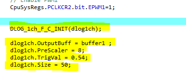
        DLOG_1ch_F_C_INIT(dlog1ch);
    
        dlog1ch.OutputBuff = buffer1 ;
        dlog1ch.PreScaler = 8;
        dlog1ch.TrigVal = 0.54;
        dlog1ch.Size = 50;
    
    
        // For this case just init GPIO pins for ePWM1, ePWM2, ePWM3
        // These functions are in the F2837xD_EPwm.c file
    
        InitEPwm1Gpio();


        // Step 3. Clear all interrupts and initialize PIE vector table:
        // Disable CPU interrupts
    
        DINT;
    
    
        // Initialize the PIE control registers to their default state.
        // The default state is all PIE interrupts disabled and flags
        // are cleared.
        // This function is found in the F2837xD_PieCtrl.c file.
    
        InitPieCtrl();
    
    
        // Disable CPU interrupts and clear all CPU interrupt flags:
    
        IER = 0x0000;
        IFR = 0x0000;
    
    
        // Initialize the PIE vector table with pointers to the shell Interrupt
        // Service Routines (ISR).
        // This will populate the entire table, even if the interrupt
        // is not used in this example.  This is useful for debug purposes.
        // The shell ISR routines are found in F2837xD_DefaultIsr.c.
        // This function is found in F2837xD_PieVect.c.
    
        InitPieVectTable();
    
        //
        // Interrupts that are used in this example are re-mapped to
        // ISR functions found within this file.
        //
        EALLOW; // This is needed to write to EALLOW protected registers
        PieVectTable.EPWM1_INT = &epwm1_isr;
    
        EDIS;   // This is needed to disable write to EALLOW protected registers
    
    
        // For this example, only initialize the ePWM
        // The TBCLKSYNC bit in the peripheral clock enable registers allows all users to globally synchronize all
        // enabled ePWM modules to the time-base clock (TBCLK).
    
        EALLOW;
        CpuSysRegs.PCLKCR0.bit.TBCLKSYNC = 0;
        ClkCfgRegs.PERCLKDIVSEL.bit.EPWMCLKDIV = 1;   //  200 / 2 = 100Mhz
        EDIS;
    
        InitEPwm1Example();
    
    
        EALLOW;
        CpuSysRegs.PCLKCR0.bit.TBCLKSYNC = 1;
        EDIS;
    
        //
        // Step 4. User specific code, enable interrupts:
        //
        // Enable CPU INT3 which is connected to EPWM1-3 INT:
        //
        IER |= M_INT3;
    
        //
        // Enable EPWM INTn in the PIE: Group 3 interrupt 1-3
        //
        PieCtrlRegs.PIEIER3.bit.INTx1 = 1;
    
    
        //
        // Enable global Interrupts and higher priority real-time debug events:
        //
        EINT;  // Enable Global interrupt INTM
        ERTM;  // Enable Global realtime interrupt DBGM
        //
        // Step 5. IDLE loop. Just sit and loop forever (optional):
        //
        for(;;)
        {
            asm ("  NOP");
        }
    }
    
    
    // epwm1_isr - EPWM1 ISR to update compare values
    
    __interrupt void epwm1_isr(void)
    {
        //static int16 var;
        //
        // Update the CMPA and CMPB value s
        //
        count++;
        //var = GpioDataRegs.GPADAT.bit.GPIO0 ;
    
        dlog1ch.Input = count;
    
    
        DLOG_1ch_F_C(dlog1ch);
    
        //update_compare(&epwm1_info);
    
        // Clear INT flag for this timer
        //
    
        EPwm1Regs.ETCLR.bit.INT = 1;
    
    
        //
        // Acknowledge this interrupt to receive more interrupts from group 3
        //
        PieCtrlRegs.PIEACK.all = PIEACK_GROUP3;
    }
    
    
    void my_clock(void)
    {
        //   Clock Setting need -> 500khz clock for pwm
        //   INTOSC1 (10 MHz) -> Clock Setting for System Clock/PLLSYSCLK
        //EALLOW;
        /*ClkCfgRegs.CLKSRCCTL1.bit.XTALOFF = 1;
        ClkCfgRegs.CLKSRCCTL1.bit.OSCCLKSRCSEL = 0x00;          // 10 Mhz -- INTOSC2
        ClkCfgRegs.SYSPLLMULT.bit.IMULT = 0x1;                 // 10 (1+0)
        ClkCfgRegs.SYSPLLMULT.bit.FMULT = 0x00;
        ClkCfgRegs.SYSCLKDIVSEL.bit.PLLSYSCLKDIV = 0x00;        // 10Mhz /1 = 10MHz
        ClkCfgRegs.SYSPLLCTL1.bit.PLLCLKEN = 0x1;              // Enable clock
         */
        ClkCfgRegs.PERCLKDIVSEL.bit.EPWMCLKDIV = 1;    // 100M
        // EDIS;
    }


    //
    // InitEPwm1Example - Initialize EPWM1 values
    //
    void InitEPwm1Example()
    {
        //
        // Setup Time Base - TBCLK
        //
        EPwm1Regs.TBCTL.bit.CTRMODE = TB_COUNT_UPDOWN; // Count up-down
        EPwm1Regs.TBPRD = EPWM1_TIMER_TBPRD;       // Set timer period
        EPwm1Regs.TBCTL.bit.PHSEN = TB_DISABLE;    // Disable phase loading
        EPwm1Regs.TBPHS.bit.TBPHS = 0x0000;        // Phase is 0
        EPwm1Regs.TBCTR = 0x0000;                  // Clear counter
    
        //EPwm1Regs.TBCTL.bit.HSPCLKDIV = 0x5;      // Clock ratio to SYSCLKOUT
        //EPwm1Regs.TBCTL.bit.CLKDIV = 0x01;
        EPwm1Regs.TBCTL.bit.HSPCLKDIV = 0x05;      // Clock ratio to SYSCLKOUT -- 100m/(10*1) = 10M
        EPwm1Regs.TBCTL.bit.CLKDIV = 0x00;
        //
        // Setup shadow register load on ZERO
        //
        EPwm1Regs.CMPCTL.bit.SHDWAMODE = CC_SHADOW;
        EPwm1Regs.CMPCTL.bit.SHDWBMODE = CC_SHADOW;
        EPwm1Regs.CMPCTL.bit.LOADAMODE = CC_CTR_ZERO;
        EPwm1Regs.CMPCTL.bit.LOADBMODE = CC_CTR_ZERO;
    
        //
        // Set Compare values
        //
        EPwm1Regs.CMPA.bit.CMPA = EPWM1_MAX_CMPA;     // Set compare A value
        EPwm1Regs.CMPB.bit.CMPB = EPWM1_MAX_CMPB;     // Set Compare B value
    
    
        // Set actions
    
        //EPwm1Regs.AQCTLA.bit.ZRO = AQ_CLEAR;        // Clear on Zero
        //EPwm1Regs.AQCTLA.bit.CBD = AQ_SET;          // Set on CMPB down
    
        EPwm1Regs.AQCTLA.bit.CAU = AQ_SET;          // SET OF CMPA UP
        EPwm1Regs.AQCTLA.bit.CBD = AQ_CLEAR;        // CLEAR ON CMPB DOWN
    
        //EPwm1Regs.AQCTLB.bit.ZRO = AQ_SET;           // Set PWM1B on Zero
        //EPwm1Regs.AQCTLB.bit.CBU = AQ_CLEAR;         // Clear PWM1B on event B,
    
    
        //
        // Interrupt where we will change the Compare Values
        //
        EPwm1Regs.ETSEL.bit.INTSEL = ET_CTR_ZERO;     // Select INT on Zero event
        EPwm1Regs.ETSEL.bit.INTEN = 1;                // Enable INT
        EPwm1Regs.ETPS.bit.INTPRD = ET_3RD;           // Generate INT on 3rd event
    
        //
        // Information this example uses to keep track
        // of the direction the CMPA/CMPB values are
        // moving, the min and max allowed values and
        // a pointer to the correct ePWM registers
        //
        epwm1_info.EPwm_CMPA_Direction = EPWM_CMP_UP;   // Start by increasing
        // CMPA & CMPB
        //epwm1_info.EPwm_CMPB_Direction = EPWM_CMP_UP;
        epwm1_info.EPwmTimerIntCount = 0;             // Zero the interrupt counter
        epwm1_info.EPwmRegHandle = &EPwm1Regs;        // Set the pointer to the
        // ePWM module
        epwm1_info.EPwmMaxCMPA = EPWM1_MAX_CMPA;      // Setup min/max
        // CMPA/CMPB values
        epwm1_info.EPwmMinCMPA = EPWM1_MIN_CMPA;
        epwm1_info.EPwmMaxCMPB = EPWM1_MAX_CMPB;
        epwm1_info.EPwmMinCMPB = EPWM1_MIN_CMPB;
    }


    // update_compare - Update the compare values for the specified EPWM
    
    void update_compare(EPWM_INFO *epwm_info)
    {
        // TO GET VARING PWM UNCOMMENT THE BELOW
    
        /*
    
       // Every 10'th interrupt, change the CMPA/CMPB values
    
       if(epwm_info->EPwmTimerIntCount == 10)
       {
           epwm_info->EPwmTimerIntCount = 0;
    
           //
           // If we were increasing CMPA, check to see if
           // we reached the max value.  If not, increase CMPA
           // else, change directions and decrease CMPA
           //
           if(epwm_info->EPwm_CMPA_Direction == EPWM_CMP_UP)
           {
               if(epwm_info->EPwmRegHandle->CMPA.bit.CMPA < epwm_info->EPwmMaxCMPA)
               {
                  epwm_info->EPwmRegHandle->CMPA.bit.CMPA++;
               }
               else
               {
                  epwm_info->EPwm_CMPA_Direction = EPWM_CMP_DOWN;
                  epwm_info->EPwmRegHandle->CMPA.bit.CMPA--;
               }
           }
    
    
           // If we were decreasing CMPA, check to see if
           // we reached the min value.  If not, decrease CMPA
           // else, change directions and increase CMPA
    
           else
           {
               if(epwm_info->EPwmRegHandle->CMPA.bit.CMPA == epwm_info->EPwmMinCMPA)
               {
                  epwm_info->EPwm_CMPA_Direction = EPWM_CMP_UP;
                  epwm_info->EPwmRegHandle->CMPA.bit.CMPA++;
               }
               else
               {
                  epwm_info->EPwmRegHandle->CMPA.bit.CMPA--;
               }
           }
    
    
           // If we were increasing CMPB, check to see if
           // we reached the max value.  If not, increase CMPB
           // else, change directions and decrease CMPB


           if(epwm_info->EPwm_CMPB_Direction == EPWM_CMP_UP)
           {
               if(epwm_info->EPwmRegHandle->CMPB.bit.CMPB < epwm_info->EPwmMaxCMPB)
               {
                  epwm_info->EPwmRegHandle->CMPB.bit.CMPB++;
               }
               else
               {
                  epwm_info->EPwm_CMPB_Direction = EPWM_CMP_DOWN;
                  epwm_info->EPwmRegHandle->CMPB.bit.CMPB--;
               }
           }
    
    
           // If we were decreasing CMPB, check to see if
           // we reached the min value.  If not, decrease CMPB
           // else, change directions and increase CMPB
    
           else
           {
               if(epwm_info->EPwmRegHandle->CMPB.bit.CMPB ==
                  epwm_info->EPwmMinCMPB)
               {
                  epwm_info->EPwm_CMPB_Direction = EPWM_CMP_UP;
                  epwm_info->EPwmRegHandle->CMPB.bit.CMPB++;
               }
               else
               {
                  epwm_info->EPwmRegHandle->CMPB.bit.CMPB--;
               }
           }
         */


        //  else
        //  {
        epwm_info->EPwmTimerIntCount++;
        //  }
    
        return;
    }
    
    
    // End of file
    
    /* Clock Setting need -> 500khz clock for pwm
     *
     * INTOSC1 (10 MHz) -> Clock Setting for System Clock/PLLSYSCLK
    
     *  ClkCfgRegs.CLKSRCCTL1.bit.OSCCLKSRCSEL = 0;     // 10 Mhz -- INTOSC2
        ClkCfgRegs.SYSPLLMULT.IMULT = 1;                // 10 (1+0)
        ClkCfgRegs.SYSPLLMULT.FMULT = 0;
        ClkCfgRegs.SYSCLKDIVSEL.PLLSYSCLKDIV = 0;      // 10Mhz /1 = 10MHz
        ClkCfgRegs.SYSPLLCTL1.PLLCLKEN = 1              // Enable clock
    
        ClkCfgRegs.PERCLKDIVSEL.EPWMCLKDIV = 0
     *
     *  So TBCLK = 10MHz
     *-------------------------------------------------------------------------
       For PWM Setting to get TBCLK ->
    
       EPwm1Regs.TBCTL.bit.HSPCLKDIV = 0x05;   // Clock ratio to SYSCLKOUT as in Register data sheet
       EPwm1Regs.TBCTL.bit.CLKDIV = 0x01;
    
       CLKDIV = 10Mhz/2
       HSPCLKDIV = CLKDIV/10
       Fpwm = 500Khz
      --------------------------------------------------------------------------
    
      TBPRD = Ftbclk / Fpwm - 1  = 10Mhz/500kHz = 199 (TBPRD)
    
      CMPA = (100% - 50(Duty Cycle) )* (199 + 1) - 1   = 99
    
      -------------------------------------------------------------------------
      Every 2 us pwm is generated
    
     * */
    

  • Saurabh,

    Please use the DLOG library available in C2000Ware-DigitalPower-SDK/libraries/utilities/dlog. The API guide availble in the root of the SDK package will explain how to use the updated library. The updated library has a restructured format. Feel free to use the 4_CH buffer in your application.

    The library in controlSUITE is not up-to-date and I cannot guarantee that it will work as expected in your application.

    Additionally, are passing by reference or passign the pointer when you make the function call?
     
    Regards,
    Ozino

  • Thanks Ozino,

    I got the DLOG module example for TMS320F28379D from which I can refer.

    Thank You.