Part Number: TMS320F28379D
Tool/software: TI C/C++ Compiler
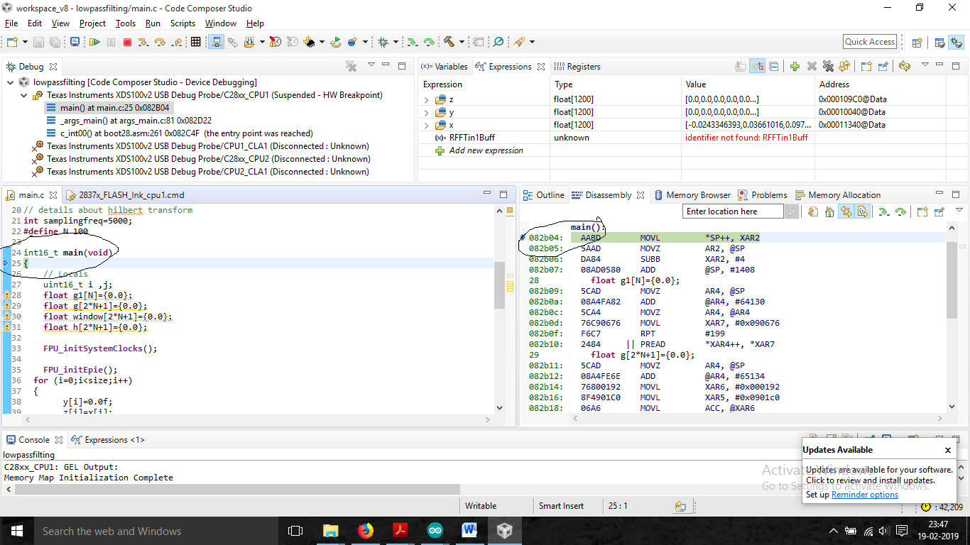
The program is stopped at inside the main()-
//*****************************************************************************
// includes
//*****************************************************************************

#include "math.h"
#include "examples_setup.h"
#include "iir_lowpass_500_fs4267.h"
#include "nav_modified.h"


//*****************************************************************************
// globals
//*****************************************************************************
float w[NUM_SECTIONS][2] = {0.0f};
float wn,yn;
float y[size],z[size];
# define pi 3.1416
// details about hilbert transform
int samplingfreq=5000;
#define N 100

int16_t main(void)
{
    // Locals
    uint16_t i ,j;
    float g1[N]={0.0};
    float g[2*N+1]={0.0};
    float window[2*N+1]={0.0};
    float h[2*N+1]={0.0};

    FPU_initSystemClocks();

    FPU_initEpie();
  for (i=0;i<size;i++)
  {
        y[i]=0.0f;
        z[i]=x[i];
  }

      /* IIR Lowpass filter of second order */

 for(j=0; j<size; j++) {
           for(i=0;i<NUM_SECTIONS;i++)
              {
                    wn = x[j]- a[i][0]*w[i][0]- a[i][1]*w[i][1];
                    yn = b[i][0]*wn +  b[i][1]*w[i][0]+  b[i][2]*w[i][1];
                    w[i][1] = w[i][0];
                    w[i][0] = wn;
                    x[j] = yn;
             }
              y[j]=yn;
            }
/* hilbert transform*/
/*for(i=0;i<=N;i++)
{
    float k= sin(pi*i/2);
    g1[i]=2*(k*k)/ (pi*i);
}

for(i=0;i<=2*N;i+1)
{
   if(i<N)
          g[i]=-g1[N-i];
   else
           g[i]=g1[i];

}*/


}
then it is enter inside the FPU_initSystemClocks(); then it terminates at line number 146 (after InitPeripheralClocks();) i am not understanding why this happens. Here I am attaching the linker file and FPU_initSystemClocks();. the nav_modified.h file consists of input data with 1200 float samples.
Hint( why happened): The program working fine intially when i pressed F8 button in the debug mode ( i got the filtered results). I checked after adding Hilbert filter block and debug, it suddently stoped some time and ccs stucked at debugger mode then i closed after 10 min. I started newly opened ccs studio then the problem started. If i work with other examples (which have FPU_initSystemclocks), working fine (no problem).
//###########################################################################
//
// FILE:   F2837xD_SysCtrl.c
//
// TITLE:  F2837xD Device System Control Initialization & Support Functions.
//
// DESCRIPTION:
//
//         Example initialization of system resources.
//
//###########################################################################
// $TI Release: F2837xD Support Library v210 $
// $Release Date: Tue Nov  1 14:46:15 CDT 2016 $
// $Copyright: Copyright (C) 2013-2016 Texas Instruments Incorporated -
//             http://www.ti.com/ ALL RIGHTS RESERVED $
//###########################################################################

//
// Included Files
//
#include "F2837xD_device.h"
#include "F2837xD_Examples.h"

#define STATUS_FAIL          0
#define STATUS_SUCCESS       1

//
// Functions that will be run from RAM need to be assigned to a different
// section.  This section will then be mapped to a load and run address using
// the linker cmd file.
//
//      *IMPORTANT*
//
//  IF RUNNING FROM FLASH, PLEASE COPY OVER THE SECTION ".TI.ramfunc" FROM
//  FLASH TO RAM PRIOR TO CALLING InitSysCtrl(). THIS PREVENTS THE MCU FROM
//  THROWING AN EXCEPTION WHEN A CALL TO DELAY_US() IS MADE.
//
#ifndef __cplusplus
    #ifdef __TI_COMPILER_VERSION__
        #if __TI_COMPILER_VERSION__ >= 15009000
            #pragma CODE_SECTION(InitFlash, ".TI.ramfunc");
            #pragma CODE_SECTION(FlashOff, ".TI.ramfunc");
        #else
            #pragma CODE_SECTION(InitFlash, "ramfuncs");
            #pragma CODE_SECTION(FlashOff, "ramfuncs");
        #endif
    #endif
#endif

//
// InitSysCtrl - Initialization of system resources.
//
void InitSysCtrl(void)
{
    //
    // Disable the watchdog
    //
    DisableDog();

#ifdef _FLASH
    //
    // Copy time critical code and Flash setup code to RAM. This includes the
    // following functions: InitFlash()
    //
    // The  RamfuncsLoadStart, RamfuncsLoadSize, and RamfuncsRunStart
    // symbols are created by the linker. Refer to the device .cmd file.
    //
    memcpy(&RamfuncsRunStart, &RamfuncsLoadStart, (size_t)&RamfuncsLoadSize);

    //
    // Call Flash Initialization to setup flash waitstates. This function must
    // reside in RAM.
    //
    InitFlash();
#endif

    //
    //      *IMPORTANT*
    //
    // The Device_cal function, which copies the ADC & oscillator calibration
    // values from TI reserved OTP into the appropriate trim registers, occurs
    // automatically in the Boot ROM. If the boot ROM code is bypassed during
    // the debug process, the following function MUST be called for the ADC and
    // oscillators to function according to specification. The clocks to the
    // ADC MUST be enabled before calling this function.
    //
    // See the device data manual and/or the ADC Reference Manual for more
    // information.
    //
#ifdef CPU1
    EALLOW;

    //
    // Enable pull-ups on unbonded IOs as soon as possible to reduce power
    // consumption.
    //
    GPIO_EnableUnbondedIOPullups();

    CpuSysRegs.PCLKCR13.bit.ADC_A = 1;
    CpuSysRegs.PCLKCR13.bit.ADC_B = 1;
    CpuSysRegs.PCLKCR13.bit.ADC_C = 1;
    CpuSysRegs.PCLKCR13.bit.ADC_D = 1;

    //
    // Check if device is trimmed
    //
    if(*((Uint16 *)0x5D1B6) == 0x0000){
        //
        // Device is not trimmed--apply static calibration values
        //
        AnalogSubsysRegs.ANAREFTRIMA.all = 31709;
        AnalogSubsysRegs.ANAREFTRIMB.all = 31709;
        AnalogSubsysRegs.ANAREFTRIMC.all = 31709;
        AnalogSubsysRegs.ANAREFTRIMD.all = 31709;
    }

    CpuSysRegs.PCLKCR13.bit.ADC_A = 0;
    CpuSysRegs.PCLKCR13.bit.ADC_B = 0;
    CpuSysRegs.PCLKCR13.bit.ADC_C = 0;
    CpuSysRegs.PCLKCR13.bit.ADC_D = 0;
    EDIS;

    //
    // Initialize the PLL control: SYSPLLMULT and SYSCLKDIVSEL.
    //
    // Defined options to be passed as arguments to this function are defined
    // in F2837xD_Examples.h.
    //
    // Note: The internal oscillator CANNOT be used as the PLL source if the
    // PLLSYSCLK is configured to frequencies above 194 MHz.
    //
    //  PLLSYSCLK = (XTAL_OSC) * (IMULT + FMULT) / (PLLSYSCLKDIV)
    //
#ifdef _LAUNCHXL_F28379D
    InitSysPll(XTAL_OSC,IMULT_40,FMULT_0,PLLCLK_BY_2);
#else
    InitSysPll(XTAL_OSC, IMULT_20, FMULT_0, PLLCLK_BY_2);
#endif // _LAUNCHXL_F28379D

#endif // CPU1

    //
    // Turn on all peripherals
    //
    InitPeripheralClocks();
}

//
// InitPeripheralClocks - Initializes the clocks for the peripherals.
//
// Note: In order to reduce power consumption, turn off the clocks to any
// peripheral that is not specified for your part-number or is not used in the
// application
//
void InitPeripheralClocks(void)
{
    EALLOW;

    CpuSysRegs.PCLKCR0.bit.CLA1 = 1;
    CpuSysRegs.PCLKCR0.bit.DMA = 1;
    CpuSysRegs.PCLKCR0.bit.CPUTIMER0 = 1;
    CpuSysRegs.PCLKCR0.bit.CPUTIMER1 = 1;
    CpuSysRegs.PCLKCR0.bit.CPUTIMER2 = 1;

#ifdef CPU1
    CpuSysRegs.PCLKCR0.bit.HRPWM = 1;
#endif

    CpuSysRegs.PCLKCR0.bit.TBCLKSYNC = 1;

#ifdef CPU1
    CpuSysRegs.PCLKCR1.bit.EMIF1 = 1;
    CpuSysRegs.PCLKCR1.bit.EMIF2 = 1;
#endif

    CpuSysRegs.PCLKCR2.bit.EPWM1 = 1;
    CpuSysRegs.PCLKCR2.bit.EPWM2 = 1;
    CpuSysRegs.PCLKCR2.bit.EPWM3 = 1;
    CpuSysRegs.PCLKCR2.bit.EPWM4 = 1;
    CpuSysRegs.PCLKCR2.bit.EPWM5 = 1;
    CpuSysRegs.PCLKCR2.bit.EPWM6 = 1;
    CpuSysRegs.PCLKCR2.bit.EPWM7 = 1;
    CpuSysRegs.PCLKCR2.bit.EPWM8 = 1;
    CpuSysRegs.PCLKCR2.bit.EPWM9 = 1;
    CpuSysRegs.PCLKCR2.bit.EPWM10 = 1;
    CpuSysRegs.PCLKCR2.bit.EPWM11 = 1;
    CpuSysRegs.PCLKCR2.bit.EPWM12 = 1;

    CpuSysRegs.PCLKCR3.bit.ECAP1 = 1;
    CpuSysRegs.PCLKCR3.bit.ECAP2 = 1;
    CpuSysRegs.PCLKCR3.bit.ECAP3 = 1;
    CpuSysRegs.PCLKCR3.bit.ECAP4 = 1;
    CpuSysRegs.PCLKCR3.bit.ECAP5 = 1;
    CpuSysRegs.PCLKCR3.bit.ECAP6 = 1;

    CpuSysRegs.PCLKCR4.bit.EQEP1 = 1;
    CpuSysRegs.PCLKCR4.bit.EQEP2 = 1;
    CpuSysRegs.PCLKCR4.bit.EQEP3 = 1;

    CpuSysRegs.PCLKCR6.bit.SD1 = 1;
    CpuSysRegs.PCLKCR6.bit.SD2 = 1;

    CpuSysRegs.PCLKCR7.bit.SCI_A = 1;
    CpuSysRegs.PCLKCR7.bit.SCI_B = 1;
    CpuSysRegs.PCLKCR7.bit.SCI_C = 1;
    CpuSysRegs.PCLKCR7.bit.SCI_D = 1;

    CpuSysRegs.PCLKCR8.bit.SPI_A = 1;
    CpuSysRegs.PCLKCR8.bit.SPI_B = 1;
    CpuSysRegs.PCLKCR8.bit.SPI_C = 1;

    CpuSysRegs.PCLKCR9.bit.I2C_A = 1;
    CpuSysRegs.PCLKCR9.bit.I2C_B = 1;

    CpuSysRegs.PCLKCR10.bit.CAN_A = 1;
    CpuSysRegs.PCLKCR10.bit.CAN_B = 1;

    CpuSysRegs.PCLKCR11.bit.McBSP_A = 1;
    CpuSysRegs.PCLKCR11.bit.McBSP_B = 1;

#ifdef CPU1
    CpuSysRegs.PCLKCR11.bit.USB_A = 1;

    CpuSysRegs.PCLKCR12.bit.uPP_A = 1;
#endif

    CpuSysRegs.PCLKCR13.bit.ADC_A = 1;
    CpuSysRegs.PCLKCR13.bit.ADC_B = 1;
    CpuSysRegs.PCLKCR13.bit.ADC_C = 1;
    CpuSysRegs.PCLKCR13.bit.ADC_D = 1;

    CpuSysRegs.PCLKCR14.bit.CMPSS1 = 1;
    CpuSysRegs.PCLKCR14.bit.CMPSS2 = 1;
    CpuSysRegs.PCLKCR14.bit.CMPSS3 = 1;
    CpuSysRegs.PCLKCR14.bit.CMPSS4 = 1;
    CpuSysRegs.PCLKCR14.bit.CMPSS5 = 1;
    CpuSysRegs.PCLKCR14.bit.CMPSS6 = 1;
    CpuSysRegs.PCLKCR14.bit.CMPSS7 = 1;
    CpuSysRegs.PCLKCR14.bit.CMPSS8 = 1;

    CpuSysRegs.PCLKCR16.bit.DAC_A = 1;
    CpuSysRegs.PCLKCR16.bit.DAC_B = 1;
    CpuSysRegs.PCLKCR16.bit.DAC_C = 1;

    EDIS;
}

//
// DisablePeripheralClocks - Gates-off all peripheral clocks.
//
void DisablePeripheralClocks(void)
{
    EALLOW;

    CpuSysRegs.PCLKCR0.all = 0;
    CpuSysRegs.PCLKCR1.all = 0;
    CpuSysRegs.PCLKCR2.all = 0;
    CpuSysRegs.PCLKCR3.all = 0;
    CpuSysRegs.PCLKCR4.all = 0;
    CpuSysRegs.PCLKCR6.all = 0;
    CpuSysRegs.PCLKCR7.all = 0;
    CpuSysRegs.PCLKCR8.all = 0;
    CpuSysRegs.PCLKCR9.all = 0;
    CpuSysRegs.PCLKCR10.all = 0;
    CpuSysRegs.PCLKCR11.all = 0;
    CpuSysRegs.PCLKCR12.all = 0;
    CpuSysRegs.PCLKCR13.all = 0;
    CpuSysRegs.PCLKCR14.all = 0;
    CpuSysRegs.PCLKCR16.all = 0;

    EDIS;
}

//
// InitFlash - This function initializes the Flash Control registers.
//
//      *CAUTION*
// This function MUST be executed out of RAM. Executing it out of OTP/Flash
// will yield unpredictable results.
//
#ifdef __cplusplus
    #ifdef __TI_COMPILER_VERSION__
        #if __TI_COMPILER_VERSION__ >= 15009000
            #pragma CODE_SECTION(".TI.ramfunc");
        #else
            #pragma CODE_SECTION("ramfuncs");
        #endif
    #endif
#endif
void InitFlash(void)
{
    EALLOW;

    //
    // Set VREADST to the proper value for the flash banks to power up
    // properly. This sets the bank power up delay.
    //
    Flash0CtrlRegs.FBAC.bit.VREADST = 0x14;

    //
    // At reset bank and pump are in sleep. A Flash access will power up the
    // bank and pump automatically.
    //
    // After a Flash access, bank and pump go to low power mode (configurable
    // in FBFALLBACK/FPAC1 registers) if there is no further access to flash.
    //
    // Power up Flash bank and pump. This also sets the fall back mode of
    // flash and pump as active.
    //
    Flash0CtrlRegs.FPAC1.bit.PMPPWR = 0x1;
    Flash0CtrlRegs.FBFALLBACK.bit.BNKPWR0 = 0x3;

    //
    // Disable Cache and prefetch mechanism before changing wait states
    //
    Flash0CtrlRegs.FRD_INTF_CTRL.bit.DATA_CACHE_EN = 0;
    Flash0CtrlRegs.FRD_INTF_CTRL.bit.PREFETCH_EN = 0;

    //
    // Set waitstates according to frequency
    //
    //      *CAUTION*
    // Minimum waitstates required for the flash operating at a given CPU rate
    // must be characterized by TI. Refer to the datasheet for the latest
    // information.
    //
    #if CPU_FRQ_200MHZ
    Flash0CtrlRegs.FRDCNTL.bit.RWAIT = 0x3;
    #endif

    #if CPU_FRQ_150MHZ
    Flash0CtrlRegs.FRDCNTL.bit.RWAIT = 0x2;
    #endif

    #if CPU_FRQ_120MHZ
    Flash0CtrlRegs.FRDCNTL.bit.RWAIT = 0x2;
    #endif

    //
    // Enable Cache and prefetch mechanism to improve performance of code
    // executed from Flash.
    //
    Flash0CtrlRegs.FRD_INTF_CTRL.bit.DATA_CACHE_EN = 1;
    Flash0CtrlRegs.FRD_INTF_CTRL.bit.PREFETCH_EN = 1;

    //
    // At reset, ECC is enabled. If it is disabled by application software and
    // if application again wants to enable ECC.
    //
    Flash0EccRegs.ECC_ENABLE.bit.ENABLE = 0xA;

    EDIS;

    //
    // Force a pipeline flush to ensure that the write to the last register
    // configured occurs before returning.
    //
    __asm(" RPT #7 || NOP");
}

//
// FlashOff - This function powers down the flash
//
//      *CAUTION*
// This function MUST be executed out of RAM. Executing it out of OTP/Flash
// will yield unpredictable results. Also you must seize the flash pump in
// order to power it down.
//
#ifdef __cplusplus
    #ifdef __TI_COMPILER_VERSION__
        #if __TI_COMPILER_VERSION__ >= 15009000
            #pragma CODE_SECTION(".TI.ramfunc");
        #else
            #pragma CODE_SECTION("ramfuncs");
        #endif
    #endif
#endif
void FlashOff(void)
{
    EALLOW;

    //
    // Set VREADST to the proper value for the flash banks to power up properly
    //
    Flash0CtrlRegs.FBAC.bit.VREADST = 0x14;

    //
    // Power down bank
    //
    Flash0CtrlRegs.FBFALLBACK.bit.BNKPWR0 = 0;

    //
    // Power down pump
    //
    Flash0CtrlRegs.FPAC1.bit.PMPPWR = 0;

    EDIS;
}

//
// SeizeFlashPump - Wait until the flash pump is available. Then take control
//                  of it using the flash pump Semaphore.
//
void SeizeFlashPump(void)
{
    EALLOW;
    #ifdef CPU1
        while (FlashPumpSemaphoreRegs.PUMPREQUEST.bit.PUMP_OWNERSHIP != 0x2)
        {
            FlashPumpSemaphoreRegs.PUMPREQUEST.all = IPC_PUMP_KEY | 0x2;
        }
    #elif defined(CPU2)
        while (FlashPumpSemaphoreRegs.PUMPREQUEST.bit.PUMP_OWNERSHIP != 0x1)
        {
            FlashPumpSemaphoreRegs.PUMPREQUEST.all = IPC_PUMP_KEY | 0x1;
        }
    #endif
    EDIS;
}

//
// ReleaseFlashPump - Release control of the flash pump using the flash pump
//                    semaphore.
//
void ReleaseFlashPump(void)
{
    EALLOW;
    FlashPumpSemaphoreRegs.PUMPREQUEST.all = IPC_PUMP_KEY | 0x0;
    EDIS;
}

//
// ServiceDog - This function resets the watchdog timer.
//
// Enable this function for using ServiceDog in the application.
//
void ServiceDog(void)
{
    EALLOW;
    WdRegs.WDKEY.bit.WDKEY = 0x0055;
    WdRegs.WDKEY.bit.WDKEY = 0x00AA;
    EDIS;
}

//
// DisableDog - This function disables the watchdog timer.
//
void DisableDog(void)
{
    volatile Uint16 temp;

    //
    // Grab the clock config first so we don't clobber it
    //
    EALLOW;
    temp = WdRegs.WDCR.all & 0x0007;
    WdRegs.WDCR.all = 0x0068 | temp;
    EDIS;
}

#ifdef CPU1
//
// InitSysPll - This function initializes the PLL registers.
//
// Note: The internal oscillator CANNOT be used as the PLL source if the
// PLLSYSCLK is configured to frequencies above 194 MHz.
//
// Note: This function uses the Watchdog as a monitor for the PLL. The user
// watchdog settings will be modified and restored upon completion.
//
void InitSysPll(Uint16 clock_source, Uint16 imult, Uint16 fmult, Uint16 divsel)
{
    Uint16 SCSR, WDCR, WDWCR, intStatus;
    if((clock_source == ClkCfgRegs.CLKSRCCTL1.bit.OSCCLKSRCSEL)    &&
       (imult        == ClkCfgRegs.SYSPLLMULT.bit.IMULT)           &&
       (fmult        == ClkCfgRegs.SYSPLLMULT.bit.FMULT)           &&
       (divsel       == ClkCfgRegs.SYSCLKDIVSEL.bit.PLLSYSCLKDIV))
    {
        //
        // Everything is set as required, so just return
        //
        return;
    }

    if(clock_source != ClkCfgRegs.CLKSRCCTL1.bit.OSCCLKSRCSEL)
    {
        switch (clock_source)
        {
            case INT_OSC1:
                SysIntOsc1Sel();
                break;

            case INT_OSC2:
                SysIntOsc2Sel();
                break;

            case XTAL_OSC:
                SysXtalOscSel();
                break;
        }
    }

    EALLOW;
    if(imult != ClkCfgRegs.SYSPLLMULT.bit.IMULT ||
       fmult != ClkCfgRegs.SYSPLLMULT.bit.FMULT)
    {
        Uint16 i;

        //
        // This bit is reset only by POR
        //
        if(DevCfgRegs.SYSDBGCTL.bit.BIT_0 == 1)
        {
            //
            // The user can optionally insert handler code here. This will only
            // be executed if a watchdog reset occurred after a failed system
            // PLL initialization. See your device user's guide for more
            // information.
            //
            // If the application has a watchdog reset handler, this bit should
            // be checked to determine if the watchdog reset occurred because
            // of the PLL.
            //
            // No action here will continue with retrying the PLL as normal.
            //
        }

        //
        // Bypass PLL and set dividers to /1
        //
        ClkCfgRegs.SYSPLLCTL1.bit.PLLCLKEN = 0;
        asm(" RPT #20 || NOP");
        ClkCfgRegs.SYSCLKDIVSEL.bit.PLLSYSCLKDIV = 0;

        //
        // Lock the PLL five times. This helps ensure a successful start.
        // Five is the minimum recommended number. The user can increase this
        // number according to allotted system initialization time.
        //
        for(i = 0; i < 5; i++)
        {
            //
            // Turn off PLL
            //
            ClkCfgRegs.SYSPLLCTL1.bit.PLLEN = 0;
            asm(" RPT #20 || NOP");

            //
            // Write multiplier, which automatically turns on the PLL
            //
            ClkCfgRegs.SYSPLLMULT.all = ((fmult << 8U) | imult);

            //
            // Wait for the SYSPLL lock counter
            //
            while(ClkCfgRegs.SYSPLLSTS.bit.LOCKS != 1)
            {
                //
                // Uncomment to service the watchdog
                //
                // ServiceDog();
            }
        }
    }

    //
    // Set divider to produce slower output frequency to limit current increase
    //
    if(divsel != PLLCLK_BY_126)
    {
         ClkCfgRegs.SYSCLKDIVSEL.bit.PLLSYSCLKDIV = divsel + 1;
    }else
    {
         ClkCfgRegs.SYSCLKDIVSEL.bit.PLLSYSCLKDIV = divsel;
    }

    //
    //      *CAUTION*
    // It is recommended to use the following watchdog code to monitor the PLL
    // startup sequence. If your application has already cleared the watchdog
    // SCRS[WDOVERRIDE] bit this cannot be done. It is recommended not to clear
    // this bit until after the PLL has been initiated.
    //

    //
    // Backup User Watchdog
    //
    SCSR = WdRegs.SCSR.all;
    WDCR = WdRegs.WDCR.all;
    WDWCR = WdRegs.WDWCR.all;

    //
    // Disable windowed functionality, reset counter
    //
    EALLOW;
    WdRegs.WDWCR.all = 0x0;
    WdRegs.WDKEY.bit.WDKEY = 0x55;
    WdRegs.WDKEY.bit.WDKEY = 0xAA;

    //
    // Disable global interrupts
    //
    intStatus = __disable_interrupts();

    //
    // Configure for watchdog reset and to run at max frequency
    //
    WdRegs.SCSR.all = 0x0;
    WdRegs.WDCR.all = 0x28;

    //
    // This bit is reset only by power-on-reset (POR) and will not be cleared
    // by a WD reset
    //
    DevCfgRegs.SYSDBGCTL.bit.BIT_0 = 1;

    //
    // Enable PLLSYSCLK is fed from system PLL clock
    //
    ClkCfgRegs.SYSPLLCTL1.bit.PLLCLKEN = 1;

    //
    // Delay to ensure system is clocking from PLL prior to clearing status bit
    //
    asm(" RPT #20 || NOP");

    //
    // Clear bit
    //
    DevCfgRegs.SYSDBGCTL.bit.BIT_0 = 0;

    //
    // Restore user watchdog, first resetting counter
    //
    WdRegs.WDKEY.bit.WDKEY = 0x55;
    WdRegs.WDKEY.bit.WDKEY = 0xAA;

    WDCR |= 0x28;                     // Setup WD key--KEY bits always read 0
    WdRegs.WDCR.all = WDCR;
    WdRegs.WDWCR.all = WDWCR;
    WdRegs.SCSR.all = SCSR & 0xFFFE;  // Mask write to bit 0 (W1toClr)

    //
    // Restore state of ST1[INTM]. This was set by the __disable_interrupts()
    // intrinsic previously.
    //
    if(!(intStatus & 0x1))
    {
        EINT;
    }

    //
    // Restore state of ST1[DBGM]. This was set by the __disable_interrupts()
    // intrinsic previously.
    //
    if(!(intStatus & 0x2))
    {
        asm(" CLRC DBGM");
    }

    //
    // 200 PLLSYSCLK delay to allow voltage regulator to stabilize prior
    // to increasing entire system clock frequency.
    //
    asm(" RPT #200 || NOP");

    //
    // Set the divider to user value
    //
    ClkCfgRegs.SYSCLKDIVSEL.bit.PLLSYSCLKDIV = divsel;
    EDIS;
}
#endif // CPU1

//
// InitAuxPll - This function initializes the AUXPLL registers.
//
// Note: For this function to properly detect PLL startup,
// SYSCLK >= 2*AUXPLLCLK after the AUXPLL is selected as the clocking source.
//
// This function will use CPU Timer 2 to monitor a successful lock of the
// AUXPLL.
//
void InitAuxPll(Uint16 clock_source, Uint16 imult, Uint16 fmult, Uint16 divsel)
{
    Uint16 i;
    Uint16 counter = 0;
    Uint16 started = 0;
    Uint16 t2_tcr, t2_tpr, t2_tprh, t2_src, t2_prescale;
    Uint32 t2_prd;

    if((clock_source == ClkCfgRegs.CLKSRCCTL2.bit.AUXOSCCLKSRCSEL) &&
       (imult        == ClkCfgRegs.AUXPLLMULT.bit.IMULT)           &&
       (fmult        == ClkCfgRegs.AUXPLLMULT.bit.FMULT)           &&
       (divsel       == ClkCfgRegs.AUXCLKDIVSEL.bit.AUXPLLDIV))
    {
        //
        // Everything is set as required, so just return
        //
        return;
    }

    switch (clock_source)
    {
        case INT_OSC2:
            AuxIntOsc2Sel();
            break;

        case XTAL_OSC:
            AuxXtalOscSel();
            break;

        case AUXCLKIN:
            AuxAuxClkSel();
            break;
    }

    //
    // Backup Timer 2 settings
    //
    t2_src = CpuSysRegs.TMR2CLKCTL.bit.TMR2CLKSRCSEL;
    t2_prescale = CpuSysRegs.TMR2CLKCTL.bit.TMR2CLKPRESCALE;
    t2_tcr = CpuTimer2Regs.TCR.all;
    t2_prd = CpuTimer2Regs.PRD.all;
    t2_tpr = CpuTimer2Regs.TPR.all;
    t2_tprh = CpuTimer2Regs.TPRH.all;

    //
    // Configure Timer 2 for AUXPLL as source in known configuration
    //
    EALLOW;
    CpuSysRegs.TMR2CLKCTL.bit.TMR2CLKSRCSEL = 0x6;
    CpuSysRegs.TMR2CLKCTL.bit.TMR2CLKPRESCALE = 0x0;    // Divide by 1

    CpuTimer2Regs.TCR.bit.TSS = 1;      // Stop timer
    CpuTimer2Regs.PRD.all = 10;         // Small PRD value to detect overflow
    CpuTimer2Regs.TPR.all = 0;
    CpuTimer2Regs.TPRH.all = 0;
    CpuTimer2Regs.TCR.bit.TIE = 0;      // Disable timer interrupts

    //
    // Set AUX Divide by 8 to ensure that AUXPLLCLK <= SYSCLK/2 while using
    // Timer 2
    //
    ClkCfgRegs.AUXCLKDIVSEL.bit.AUXPLLDIV = 0x3;
    EDIS;

    while((counter < 5) && (started == 0))
    {
        EALLOW;
        ClkCfgRegs.AUXPLLCTL1.bit.PLLEN = 0;    // Turn off AUXPLL
        asm(" RPT #20 || NOP");                 // Small delay for power down

        //
        // Set integer and fractional multiplier, which automatically turns on
        // the PLL
        //
        ClkCfgRegs.AUXPLLMULT.all = ((fmult << 8U) | imult);

        //
        // Enable AUXPLL
        //
        ClkCfgRegs.AUXPLLCTL1.bit.PLLEN = 1;
        EDIS;

        //
        // Wait for the AUXPLL lock counter
        //
        while(ClkCfgRegs.AUXPLLSTS.bit.LOCKS != 1)
        {
            //
            // Uncomment to service the watchdog
            //
            // ServiceDog();
        }

        //
        // Enable AUXPLLCLK to be fed from AUX PLL
        //
        EALLOW;
        ClkCfgRegs.AUXPLLCTL1.bit.PLLCLKEN = 1;
        asm(" RPT #20 || NOP");

        //
        // CPU Timer 2 will now be setup to be clocked from AUXPLLCLK. This is
        // used to test that the PLL has successfully started.
        //
        CpuTimer2Regs.TCR.bit.TRB = 1;      // Reload period value
        CpuTimer2Regs.TCR.bit.TSS = 0;      // Start Timer

        //
        // Check to see timer is counting properly
        //
        for(i = 0; i < 1000; i++)
        {
            //
            // Check overflow flag
            //
            if(CpuTimer2Regs.TCR.bit.TIF)
            {
                //
                // Clear overflow flag
                //
                CpuTimer2Regs.TCR.bit.TIF = 1;

                //
                // Set flag to indicate PLL started and break out of for-loop
                //
                started = 1;
                break;
            }
        }

        //
        // Stop timer
        //
        CpuTimer2Regs.TCR.bit.TSS = 1;
        counter++;
        EDIS;
    }

    if(started == 0)
    {
        //
        // AUX PLL may not have started. Reset multiplier to 0 (bypass PLL).
        //
        EALLOW;
        ClkCfgRegs.AUXPLLMULT.all = 0;
        EDIS;

        //
        // The user should put some handler code here based on how this
        // condition should be handled in their application.
        //
        asm(" ESTOP0");
    }

    //
    // Set divider to desired value
    //
    EALLOW;
    ClkCfgRegs.AUXCLKDIVSEL.bit.AUXPLLDIV = divsel;

    //
    // Restore Timer 2 configuration
    //
    CpuSysRegs.TMR2CLKCTL.bit.TMR2CLKSRCSEL = t2_src;
    CpuSysRegs.TMR2CLKCTL.bit.TMR2CLKPRESCALE = t2_prescale;
    CpuTimer2Regs.TCR.all = t2_tcr;
    CpuTimer2Regs.PRD.all = t2_prd;
    CpuTimer2Regs.TPR.all = t2_tpr;
    CpuTimer2Regs.TPRH.all = t2_tprh;

    //
    // Reload period value
    //
    CpuTimer2Regs.TCR.bit.TRB = 1;
    EDIS;
}

//
// CsmUnlock - This function unlocks the CSM. User must replace 0xFFFF's with
//             current password for the DSP. Returns 1 if unlock is successful.
//
Uint16 CsmUnlock(void)
{
    volatile Uint16 temp;

    //
    // Load the key registers with the current password. The 0xFFFF's are dummy
    // passwords.  User should replace them with the correct password for the
    // DSP.
    //
    EALLOW;
    DcsmZ1Regs.Z1_CSMKEY0 = 0xFFFFFFFF;
    DcsmZ1Regs.Z1_CSMKEY1 = 0xFFFFFFFF;
    DcsmZ1Regs.Z1_CSMKEY2 = 0xFFFFFFFF;
    DcsmZ1Regs.Z1_CSMKEY3 = 0xFFFFFFFF;

    DcsmZ2Regs.Z2_CSMKEY0 = 0xFFFFFFFF;
    DcsmZ2Regs.Z2_CSMKEY1 = 0xFFFFFFFF;
    DcsmZ2Regs.Z2_CSMKEY2 = 0xFFFFFFFF;
    DcsmZ2Regs.Z2_CSMKEY3 = 0xFFFFFFFF;
    EDIS;

    return(0);
}

//
// SysIntOsc1Sel - This function switches to Internal Oscillator 1.
//
void SysIntOsc1Sel(void)
{
    EALLOW;
    ClkCfgRegs.CLKSRCCTL1.bit.OSCCLKSRCSEL = 2;     // Clk Src = INTOSC1
    EDIS;
}

//
// SysIntOsc2Sel - This function switches to Internal oscillator 2.
//
void SysIntOsc2Sel(void)
{
    EALLOW;
    ClkCfgRegs.CLKSRCCTL1.bit.INTOSC2OFF=0;         // Turn on INTOSC2
    ClkCfgRegs.CLKSRCCTL1.bit.OSCCLKSRCSEL = 0;     // Clk Src = INTOSC2
    EDIS;
}

//
// SysXtalOscSel - This function switches to External CRYSTAL oscillator.
//
void SysXtalOscSel(void)
{
    EALLOW;
    ClkCfgRegs.CLKSRCCTL1.bit.XTALOFF=0;            // Turn on XTALOSC
    ClkCfgRegs.CLKSRCCTL1.bit.OSCCLKSRCSEL = 1;     // Clk Src = XTAL
    EDIS;
}

//
// AuxIntOsc2Sel - This function switches to Internal oscillator 2.
//
void AuxIntOsc2Sel(void)
{
    EALLOW;
    ClkCfgRegs.CLKSRCCTL1.bit.INTOSC2OFF=0;         // Turn on INTOSC2
    ClkCfgRegs.CLKSRCCTL2.bit.AUXOSCCLKSRCSEL = 0;  // Clk Src = INTOSC2
    EDIS;
}

//
// AuxXtalOscSel - This function switches to External CRYSTAL oscillator.
//
void AuxXtalOscSel(void)
{
    EALLOW;
    ClkCfgRegs.CLKSRCCTL1.bit.XTALOFF=0;            // Turn on XTALOSC
    ClkCfgRegs.CLKSRCCTL2.bit.AUXOSCCLKSRCSEL = 1;  // Clk Src = XTAL
    EDIS;
}

//
// AuxAUXCLKOscSel - This function switches to AUXCLKIN (from a GPIO).
//
void AuxAuxClkSel(void)
{
    EALLOW;
    ClkCfgRegs.CLKSRCCTL2.bit.AUXOSCCLKSRCSEL = 2; // Clk Src = XTAL
    EDIS;
}

//
// IDLE - Enter IDLE mode (single CPU).
//
void IDLE(void)
{
    EALLOW;
    CpuSysRegs.LPMCR.bit.LPM = LPM_IDLE;
    EDIS;
    asm(" IDLE");
}

//
// STANDBY - Enter STANDBY mode (single CPU).
//
void STANDBY(void)
{
    EALLOW;
    CpuSysRegs.LPMCR.bit.LPM = LPM_STANDBY;
    EDIS;
    asm(" IDLE");
}

//
// HALT - Enter HALT mode (dual CPU). Puts CPU2 in IDLE mode first.
//
void HALT(void)
{
#if defined(CPU2)
    IDLE();
#elif defined(CPU1)
    EALLOW;
    CpuSysRegs.LPMCR.bit.LPM = LPM_HALT;
    EDIS;

    while(DevCfgRegs.LPMSTAT.bit.CPU2LPMSTAT != 0x1);

    EALLOW;
    ClkCfgRegs.SYSPLLCTL1.bit.PLLCLKEN = 0;
    ClkCfgRegs.SYSPLLCTL1.bit.PLLEN = 0;
    EDIS;
    asm(" IDLE");
#endif
}

//
// HIB - Enter HIB mode (dual CPU). Puts CPU2 in STANDBY first. Alternately,
//       CPU2 may be in reset.
void HIB(void)
{
#if defined(CPU2)
    STANDBY();
#elif defined(CPU1)
    EALLOW;
    CpuSysRegs.LPMCR.bit.LPM = LPM_HIB;
    EDIS;

    while((DevCfgRegs.LPMSTAT.bit.CPU2LPMSTAT == 0x0) &&
          (DevCfgRegs.RSTSTAT.bit.CPU2RES == 1));

    DisablePeripheralClocks();
    EALLOW;
    ClkCfgRegs.SYSPLLCTL1.bit.PLLCLKEN = 0;
    ClkCfgRegs.SYSPLLCTL1.bit.PLLEN = 0;
    EDIS;
    asm(" IDLE");
#endif
}