This thread has been locked.

If you have a related question, please click the "Ask a related question" button in the top right corner. The newly created question will be automatically linked to this question.

LAUNCHXL-F28377S: SCI Echoback example is not working.

Part Number: LAUNCHXL-F28377S

Hi,


I’m trying to run the ControlSuite’s SCI Echoback example for LAUNCHXL-F28377s. Nothing appears in the TeraTerm window. I’ve searched the forum and didn’t see a solution that helped. 

  • Windows Device Manager recognizes the COM port created by the XDS100v2 and reports that it is working correctly.
  • I set TeraTerm to open that COM port, baud rate 9600.
  • According to the F28377s TRM, the HBAUD/LBAUD registers should be 0x0002/0x008a for 9600 baud with 200Mhz Sys Clock and 50Mhz LOSPCP. The demo uses 0x0002/0x008b, but that shouldn't be the problem. I don’t know what the BRR hex values in Table 18-3 are supposed to represent.
  • I noticed after importing the project in CCS that unless you manually add the pre-define symbol _LAUNCHXL_F28377S, the project will not configure 200Mhz CPU speed. I am running the source code without modifications.
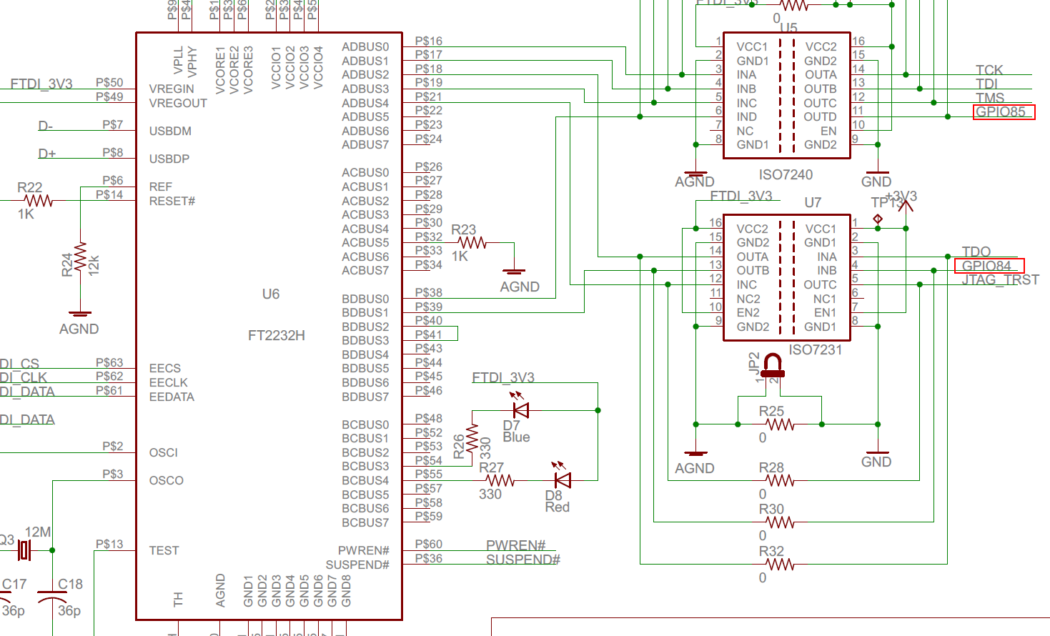
  • Looking in the Launchpad’s UG (SPRUI25C) Tables 1-4, I see no mention of GPIOs 28, 29 or SCITXDA or SCIRXDA (though SCITXDB and SCIRXDB are mentioned multiple times), so I assume no extra connection to the board is required other than the JTAG USB.
  • When I step over the first call scia_msg() that sends “Hello World”, I notice the SCIRXST registers a few receive errors:


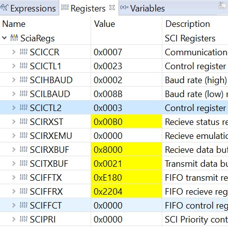
I can't think of anything else to check. Hopefully I missed something simple!

Thanks, dave

  • Hi Dave,

    I'd generally recommend you get your C2000 SW examples from C2000ware (newer) vs ControlSUITE (older) when possible.  

    Yes, you will need to add the pre-defined launchpad symbol to get the default project to run at 200MHz.  This is because the X1 input clock can vary between EVMs (i.e. Launchpad vs. ControlCard) or a custom board.  By default the SW projects assume 20MHz X1 frequency (which is correct for the ControlCard).  You could alternately go in and change the PLL settings in the device initialization function to match your particular board.

    The values in the "Asynchronous Baud Register Values for Common SCI Bit Rates" table assume 100MHz LSPCLK.  50MHz should be the default, but you might want to verify in the expressions window (after the code has run) that LOSPCP.bit.LSPCLKDIV is indeed '2' = /4.  

    The project will, by default, use GPIO28 and GPIO29, which would assume the use of a transceiver and cable:

    //! \b External \b Connections \n
    //! Connect the SCI-A port to a PC via a transceiver and cable.
    //! - GPIO28 is SCI_A-RXD (Connect to Pin3, PC-TX, of serial DB9 cable)
    //! - GPIO29 is SCI_A-TXD (Connect to Pin2, PC-RX, of serial DB9 cable)

    You could instead change the GPIOs to GPIO84 and GPIO85 if you wanted to use the FTDI connection (virtual COM port created when you plug in the EVM) which shouldn't require a cable and transceiver: