Part Number: TMS320F28035
Hi Experts,
I want to ask a question about ADC sampling issue.
The below is the test phenomenon/ results:
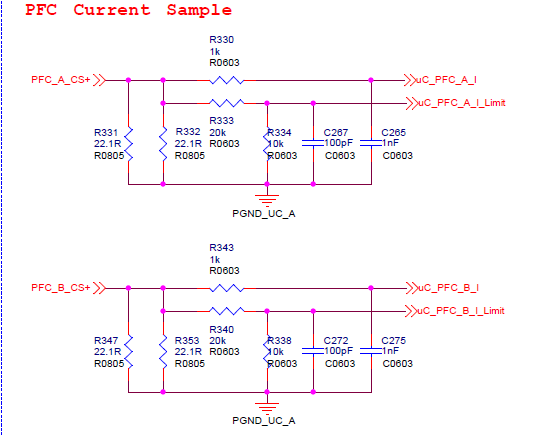
1# As the below figure shown, the big input current spike often occurs when PFC system running, while the input voltage spike is small.
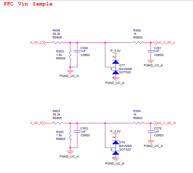
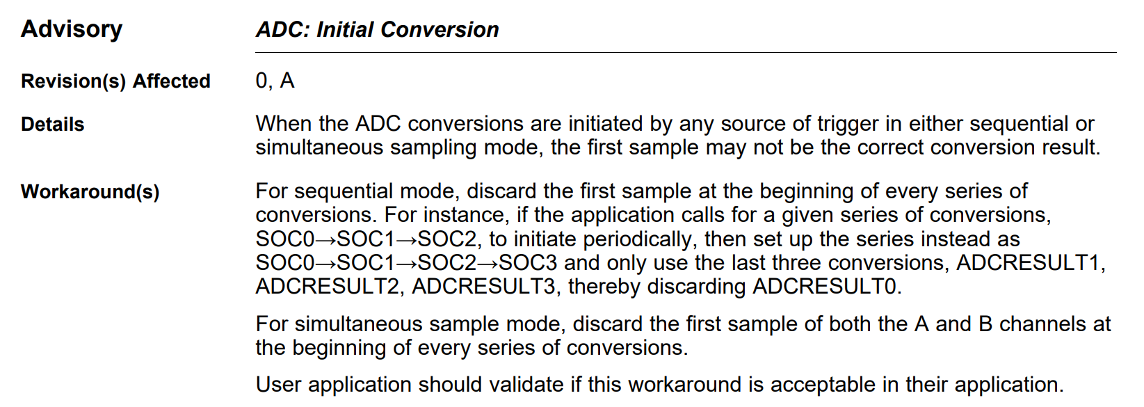
However, in the figure 2, ADC sampling of input voltage wave gain from CAN bus, is different with the wave in figure 1 gain from Oscilloscope.
Through the ADC sampling waves, the voltage sampling value is not right, which is too big than the value in Oscilloscope.
2# The current spike happened period is around 0.46s.
3# When change the ACQPS value from 6 to 8, and the spike disappears, however this situation just test once.
4# When add some codes in "ISR" or "for" loop, sometimes, there are spikes while sometimes there are not.
Customer wonder that:
1# Is the voltage incorrect sampling caused the current spike?
2# What caused the voltage incorrect sampling, is that just because the ACQPS value is too small?
3# Why add code in "ISR" or "for" loop, the spike phenomenon could disappear sometimes?
Thanks!


/***********************************************************************************
 * FileName: 2016_newOBC_Adc.c
 *
 * ���ܣ�          AD���ã�AD���ݴ���
 *
 * ���÷�Χ��
 *
 * Created on: 2016��3��18��
 *
 * Author: Administrator
 ***********************************************************************************/

#include "2016_newOBC_main.h"    /*��������ͷ�ļ�*/

void AdcInit(void)
{
    InitAdc();
    EALLOW;
    // 1.���ò���ģʽΪ˳�����ģʽ,���Ϊ��һ����ģʽ
    AdcRegs.ADCSAMPLEMODE.all       = 0;

    // 2.ʹ���ڲ��¶ȴ�����
    AdcRegs.ADCCTL1.bit.TEMPCONV    = 1;

    // 3.����SOCx��Ӧ����ͨ��,[����]��궨��RESULT_XXX���Ӧ
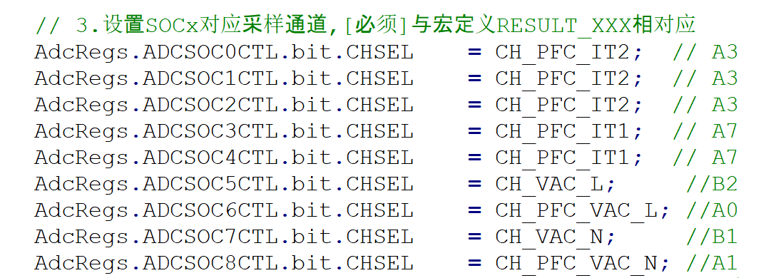
    AdcRegs.ADCSOC0CTL.bit.CHSEL    = CH_PFC_IT2;  // ���ٵ����źŲ���,��PWM����
    AdcRegs.ADCSOC1CTL.bit.CHSEL    = CH_PFC_IT2;  // CH_PFC_IN_IAC;
    AdcRegs.ADCSOC2CTL.bit.CHSEL    = CH_PFC_IT2;  // CH_PFC_IN_IAC
    AdcRegs.ADCSOC3CTL.bit.CHSEL    = CH_PFC_IT1;  // CH_PFC_IN_IAC;
    AdcRegs.ADCSOC4CTL.bit.CHSEL    = CH_PFC_IT1;  // CH_PFC_IN_IAC;
    AdcRegs.ADCSOC5CTL.bit.CHSEL    = CH_VAC_L;     //result_5
    AdcRegs.ADCSOC6CTL.bit.CHSEL    = CH_PFC_VAC_L; //result_6
    AdcRegs.ADCSOC7CTL.bit.CHSEL    = CH_VAC_N;     //result_7
    AdcRegs.ADCSOC8CTL.bit.CHSEL    = CH_PFC_VAC_N; //result_8
    AdcRegs.ADCSOC9CTL.bit.CHSEL    = CH_VBULK;  // ����Ϊ�����źŲ���
    AdcRegs.ADCSOC10CTL.bit.CHSEL   = CH_VBULK;   //result_10
    AdcRegs.ADCSOC11CTL.bit.CHSEL   = CH_NTC_AMB;
    AdcRegs.ADCSOC12CTL.bit.CHSEL   = CH_NTC_LLC;
    AdcRegs.ADCSOC13CTL.bit.CHSEL 	= CH_LLC_DRV_UDC;//CH_PFC_IN_IAC;
    AdcRegs.ADCSOC14CTL.bit.CHSEL   = CH_LLC_DRV_UDC;
    AdcRegs.ADCSOC15CTL.bit.CHSEL   = CH_NTC_PFC;  //pfc�¶�

    // ����SOCx����Դ  //debug: ��Ҫ����ʵ��������е���
/*    AdcRegs.ADCSOC0CTL.bit.TRIGSEL  = ADCTRIG_EPWM1_SOCA;  //PFC����㴥��
    AdcRegs.ADCSOC1CTL.bit.TRIGSEL  = ADCTRIG_EPWM1_SOCA;  //IT1
    AdcRegs.ADCSOC2CTL.bit.TRIGSEL  = ADCTRIG_EPWM1_SOCA;  //IT1
    AdcRegs.ADCSOC3CTL.bit.TRIGSEL  = ADCTRIG_EPWM2_SOCA;  //IT2
    AdcRegs.ADCSOC4CTL.bit.TRIGSEL  = ADCTRIG_EPWM2_SOCA;  //IT2
    AdcRegs.ADCSOC5CTL.bit.TRIGSEL  = ADCTRIG_EPWM1_SOCA;
    AdcRegs.ADCSOC6CTL.bit.TRIGSEL  = ADCTRIG_EPWM1_SOCA;
    AdcRegs.ADCSOC7CTL.bit.TRIGSEL  = ADCTRIG_EPWM2_SOCA;
    AdcRegs.ADCSOC8CTL.bit.TRIGSEL  = ADCTRIG_EPWM2_SOCA;   //��LLC����pwm����
    AdcRegs.ADCSOC9CTL.bit.TRIGSEL  = ADCTRIG_EPWM1_SOCA;   //��LLC����pwm����
    AdcRegs.ADCSOC10CTL.bit.TRIGSEL  = ADCTRIG_EPWM1_SOCA;
    AdcRegs.ADCSOC11CTL.bit.TRIGSEL  = ADCTRIG_CPU_TINT0;
    AdcRegs.ADCSOC12CTL.bit.TRIGSEL  = ADCTRIG_CPU_TINT0;
    AdcRegs.ADCSOC13CTL.bit.TRIGSEL  = ADCTRIG_CPU_TINT0;
    AdcRegs.ADCSOC14CTL.bit.TRIGSEL  = ADCTRIG_CPU_TINT0;
    AdcRegs.ADCSOC15CTL.bit.TRIGSEL  = ADCTRIG_CPU_TINT0;
*/

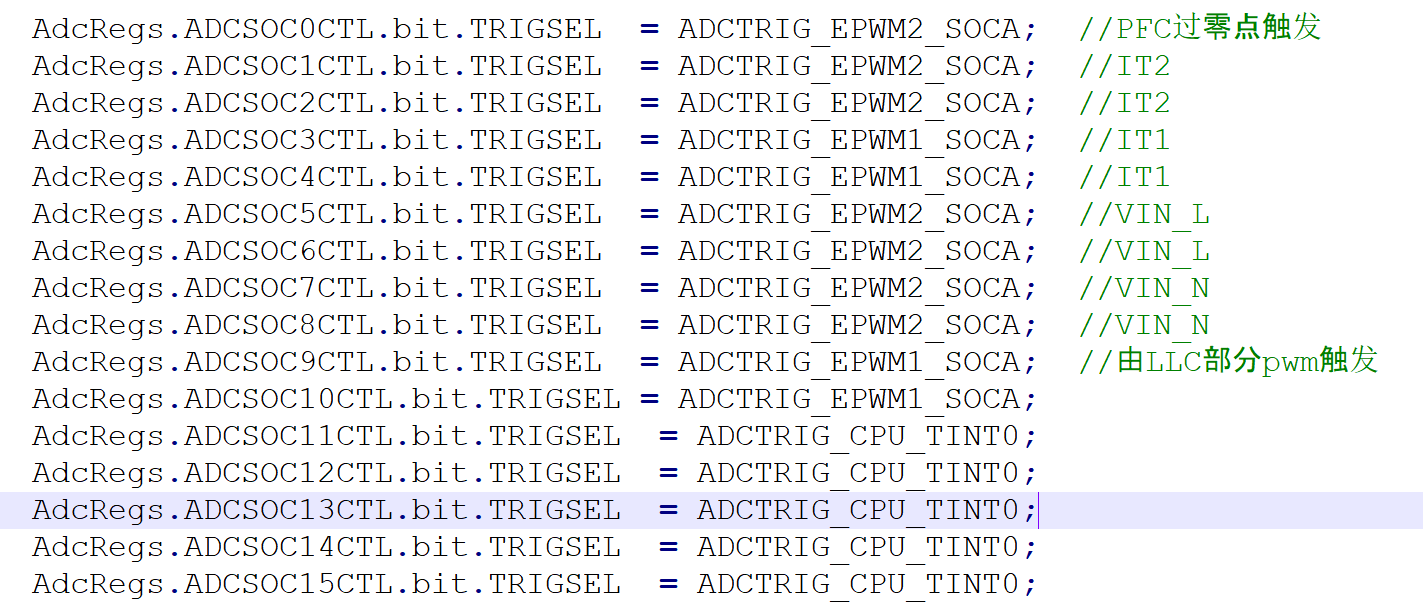
    AdcRegs.ADCSOC0CTL.bit.TRIGSEL  = ADCTRIG_EPWM2_SOCA;  //PFC����㴥��
    AdcRegs.ADCSOC1CTL.bit.TRIGSEL  = ADCTRIG_EPWM2_SOCA;  //IT2
    AdcRegs.ADCSOC2CTL.bit.TRIGSEL  = ADCTRIG_EPWM2_SOCA;  //IT2
    AdcRegs.ADCSOC3CTL.bit.TRIGSEL  = ADCTRIG_EPWM1_SOCA;  //IT1
    AdcRegs.ADCSOC4CTL.bit.TRIGSEL  = ADCTRIG_EPWM1_SOCA;  //IT1
    AdcRegs.ADCSOC5CTL.bit.TRIGSEL  = ADCTRIG_EPWM2_SOCA;  //VIN_L
    AdcRegs.ADCSOC6CTL.bit.TRIGSEL  = ADCTRIG_EPWM2_SOCA;  //VIN_L
    AdcRegs.ADCSOC7CTL.bit.TRIGSEL  = ADCTRIG_EPWM2_SOCA;  //VIN_N
    AdcRegs.ADCSOC8CTL.bit.TRIGSEL  = ADCTRIG_EPWM2_SOCA;  //VIN_N
    AdcRegs.ADCSOC9CTL.bit.TRIGSEL  = ADCTRIG_EPWM1_SOCA;  //��LLC����pwm����
    AdcRegs.ADCSOC10CTL.bit.TRIGSEL = ADCTRIG_EPWM1_SOCA;
    AdcRegs.ADCSOC11CTL.bit.TRIGSEL  = ADCTRIG_CPU_TINT0;
    AdcRegs.ADCSOC12CTL.bit.TRIGSEL  = ADCTRIG_CPU_TINT0;
    AdcRegs.ADCSOC13CTL.bit.TRIGSEL  = ADCTRIG_CPU_TINT0;
    AdcRegs.ADCSOC14CTL.bit.TRIGSEL  = ADCTRIG_CPU_TINT0;
    AdcRegs.ADCSOC15CTL.bit.TRIGSEL  = ADCTRIG_CPU_TINT0;


    // ���ò�������(���ڿ�� = ACQPS_Value + 1)
    #define ACQPS_Value 6
    AdcRegs.ADCSOC0CTL.bit.ACQPS    = ACQPS_Value;
    AdcRegs.ADCSOC1CTL.bit.ACQPS    = ACQPS_Value;
    AdcRegs.ADCSOC2CTL.bit.ACQPS    = ACQPS_Value;
    AdcRegs.ADCSOC3CTL.bit.ACQPS    = ACQPS_Value;
    AdcRegs.ADCSOC4CTL.bit.ACQPS    = ACQPS_Value;
    AdcRegs.ADCSOC5CTL.bit.ACQPS    = ACQPS_Value;
    AdcRegs.ADCSOC6CTL.bit.ACQPS    = ACQPS_Value;
    AdcRegs.ADCSOC7CTL.bit.ACQPS    = ACQPS_Value;
    AdcRegs.ADCSOC8CTL.bit.ACQPS    = ACQPS_Value;
    AdcRegs.ADCSOC9CTL.bit.ACQPS    = ACQPS_Value;
    AdcRegs.ADCSOC10CTL.bit.ACQPS   = ACQPS_Value;
    AdcRegs.ADCSOC11CTL.bit.ACQPS   = ACQPS_Value;
    AdcRegs.ADCSOC12CTL.bit.ACQPS   = ACQPS_Value;
    AdcRegs.ADCSOC13CTL.bit.ACQPS   = ACQPS_Value;
    AdcRegs.ADCSOC14CTL.bit.ACQPS   = ACQPS_Value;
    AdcRegs.ADCSOC15CTL.bit.ACQPS   = ACQPS_Value;
    #undef ACQPS_Value

    // ���ò���ͨ�����ȼ�:ͨ��0 & 1 : Ϊ���ٵ�������ͨ��,�����������,��Ϊ������PWMʱЧ
    AdcRegs.SOCPRICTL.bit.SOCPRIORITY = PRIORITY_SOC0_8;

    // �����жϱ�־��������: �������ʱ
    AdcRegs.ADCCTL1.bit.INTPULSEPOS = 1;

    // ����ADC�жϴ���SOCx
    AdcRegs.ADCINTSOCSEL1.all       = 0;
    AdcRegs.ADCINTSOCSEL2.all       = 0;

    // �����ж��źŵĴ���Դ
    AdcRegs.INTSEL1N2.bit.INT1SEL  = ADC_EOC08;  //L_N�������
 //   AdcRegs.INTSEL1N2.bit.INT2SEL  = ADC_EOC04;  //CT2

   // ʹ���ж��ź�,��������ζ��ᴥ���ж�,������ʹ���ź�
    AdcRegs.INTSEL1N2.bit.INT1E     = 1;      //CT1
 //   AdcRegs.INTSEL1N2.bit.INT2E     = 1;      //CT2
   // ������������,���´β�������ǰǰ�β�����ɱ�־��������
    AdcRegs.INTSEL1N2.bit.INT1CONT  = 0;
    EDIS;

    DELAY_US(1000L);
}


/*************************************************************************
 *  Function: AdcFinish
 *  ����˵����  �ж�AD���������Ƿ����
 ************************************************************************/
Uint16 AdcFinish(void)
{
    Uint16 result = 0;
    if (AdcRegs.ADCINTFLG.bit.ADCINT1)
    {
        AdcRegs.ADCINTFLGCLR.bit.ADCINT1 = 1;    //Clear ADCINT1
        result = 1;                              //ת�����
    }
    return (result);
}


/***********************************************************************************
 * The End
 ***********************************************************************************/